カテゴリー
category_usa

High Current PCB

What Is a High Current PCB?

As the electrification of automobiles such as hybrids, EVs, and PHEVs advances, printed circuit boards (PCBs) are required to support high current PCBs.

Although it is possible to respond to high current PCBs by increasing the pattern width, there is a limit to the pattern of expansion width in the current situation, where smaller electronic components are required at the same time.

However, the current demand for miniaturization of electronic components has limited the ability to expand the pattern width.

While the copper thickness of a typical PCB is 35 µm, high current PCBs are capable of handling high currents by realizing circuits with a copper thickness of up to 2000 µm.

Uses of High Current PCBs

They are used for miniaturization of electrical components with large electrical loads, such as high-current control circuits, high-power supplies, switching and motor circuits, breakers, fuse boxes, etc., for electric vehicles, hybrids, PHEVs, robots, as well as gasoline engine vehicles, which are becoming more and more electronic.

They are also used as printed circuit boards with excellent thermal diffusion and dissipation as part of LED heat dissipation measures for power devices that generate heat at high temperatures, such as IGBTs, power MOSFETs, Schottky diodes, and thyristors, as well as for traffic signals and outdoor billboards.

Principle of High Current PCBs

Compared to ordinary PCBs, high current PCBs need to carry much higher current, for example, 2A to 100A for automotive electronic devices, and it is necessary to create a copper pattern cross-sectional area that matches the amount of current flowing in the pattern.

An important point in designing high current PCBs is that the etching method (dissolving copper foil), which is the general manufacturing method for current PCBs, creates a pattern by etching copper based on an etch resist pattern drawn on the copper surface. However, since the copper foil thickness of high-current boards is thick, dissolution proceeds from the top of the copper foil in this method, resulting in etching not only in the depth direction but also between patterns, resulting in a trapezoidal cross-section of the pattern and a loss of cross-sectional area accuracy.

Therefore, it is not desirable to design high current PCBs using the same method as that used for ordinary printed circuit boards for signals.

However, there are significant advantages for users who mass-produce high current PCBs, and we expect that improvements in materials and manufacturing methods will lead to lower costs and increased use of high current PCBs in the future. However, it is a big advantage for users who mass-produce high-current products.

カテゴリー
category_usa

Atmospheric pressure plasma device

What Is an Atmospheric Pressure Plasma Device?

Atmospheric pressure plasma devices are devices that use plasma discharge to remove organic matter and oxides.

They are characterized by the fact that they consist only of reaction gas for plasma generation and a power supply, and do not require a decompression tank. Because they can remove organic films on the surface of polymer materials and oxides on metal surfaces, they are widely used not only for industrial applications but also for academic research. Compact devices have also been developed and are used in a variety of fields.

Specifically, they are used for sterilization of medical instruments, sterilization in food processing plants, and surface treatment in semiconductor manufacturing processes. Furthermore, environmental issues are also being addressed, and atmospheric pressure plasma devices are being used to develop technologies for purifying exhaust gases and wastewater.

Uses of Atmospheric Pressure Plasma Devices

Atmospheric pressure plasma device can modify the surface of resins, films, and polymer materials. Surface modification can be performed at high speed and without damaging the surface.

They are widely used in the manufacture of semiconductors, electronic components, plastics, and glass products. Specifically, surface cleaning using reactions with plasma and changes in the composition of polymer surfaces can be expected to improve hydrophilicity.

In addition, even materials such as polyethylene and polypropylene can be bonded with adhesives (urethane or epoxy-based) to increase their bonding strength. For this reason, atmospheric pressure plasma device is also used for products such as automobile parts and medical devices, where adhesive strength is required.

Principle of Atmospheric Pressure Plasma Devices

An atmospheric pressure plasma device uses a high-frequency pulse power supply to generate a plasma discharge, and the active species such as electrons and ions in the plasma are used for surface modification and cleaning.

Plasma is the fourth state of matter and is a high-energy state. In plasma, electrons and remaining ions are mixed together as a result of the ionization phenomena in which electrons are ejected from atoms, but the overall charge distribution is maintained as neutral.

In atmospheric pressure plasma device, active species in the plasma cause chemical reactions on surfaces, enabling surface modification and cleaning. For example, when oxygen plasma is generated, it bonds with the carbon atoms that make up the resin and desorbs them from the surface as CO2. This chemical reaction can be used to clean and modify the surface of resins, films, and polymer materials.

Atmospheric pressure plasma device is also used in the manufacture of semiconductors, electronic components, plastics, and glass products. Surface cleaning and changes in the composition of polymer surfaces using reactions with plasma are expected to improve hydrophilicity and enhance adhesive strength.

Atmospheric pressure plasma devices are low-temperature plasmas that can generate plasma at relatively low temperatures compared to thermal plasmas, which are in a high-temperature state, and can be generated by using a high-frequency pulse power supply.

Types of Atmospheric Pressure Plasma Devices

There are two main types of atmospheric pressure plasma devices: corona discharge plasma devices and microwave plasma devices

1. Corona Discharge Plasma Device

Corona discharge plasma devices are based on plasma generated using a high-frequency power supply. By applying a high-frequency voltage between the electrodes, plasma is discharged, and surface modification and cleaning are performed through chemical reactions with the reaction gas. It is characterized by low temperatures and is effective for polymer materials such as resins and films.

2. Microwave Plasma System

Microwave plasma systems use microwaves to generate plasma. By pouring in a reaction gas and applying a high-frequency electric field, the microwaves are absorbed by the reaction gas and plasma is generated. It can generate high-temperature plasma, which is used for high-resolution surface modification and thin-film formation of metals and ceramics.

カテゴリー
category_usa

Bidirectional DC Power Supply

What Is a Bidirectional DC Power Supply?

Bidirectional DC Power Supplies

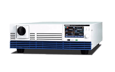
A bidirectional DC power supply is a power device that can supply power in DC and receive power at the same time.

Conventional DC power supplies supply power unidirectionally and cannot control the flow of power in the opposite direction. With bidirectional DC power supply, it is possible to both supply and collect power. It can also flexibly supply and recover power.

As a result, this technology is attracting attention as useful for improving energy efficiency and stabilizing power networks. It is also being used as a power source for electric vehicles.

Uses of Bidirectional DC Power Supplies

Bidirectional DC power supplies are used in a variety of applications. The following are typical applications:

1. Renewable Energy Power Generation Systems

Bidirectional DC power supplies are incorporated into renewable energy power generation systems, such as solar and wind power generation systems. By using bidirectional DC power supply, DC power from renewable energy sources can be efficiently recovered and supplied to the power network.

It may also be applied to microgrids. Microgrids are small-scale power systems. Renewable energy generation, storage batteries, and power conversion equipment are combined to form an independent power system.

2. Automobiles

It is also important for electric vehicle charging infrastructure. DC charging stations use bidirectional DC power supply to charge electric vehicles by supplying power from storage batteries. It is also possible to control the reverse power flow from the storage batteries to supply power to the power network.

3. Other

Bidirectional DC power supply is also used in vehicle infrastructure, such as electric buses and trams. By using bidirectional DC power supply, power supply and recovery of backflow power can be performed efficiently.

It can also be applied to construction machinery. Forklifts and cranes are examples. Since construction machinery is frequently moved and stopped, bidirectional DC power supply can realize efficient operation.

Principle of Bidirectional DC Power Supplies

The components of a bidirectional DC power supply include a power converter and a control system. These devices and systems convert, control, and protect power.

Bidirectional DC power supplies use inverters and converters to convert DC to AC and vice versa. This makes it possible to control power supply and recovery in both directions.

Also important is the control system used to control power supply and recovery. The control system controls the power flow, voltage, and current to achieve the required power supply and recovery. Note that the system is also called a regenerative power source because of the way power is returned to the grid side.

When storage batteries are used, a storage battery management system is also required. Lithium-ion batteries or lead-acid batteries are used as storage batteries. The storage battery management system monitors the charge and discharge status of the storage batteries and controls the supply and recovery of power at appropriate times.

How to Select a Bidirectional DC Power Supply

The following factors exist when selecting a bidirectional DC power supply:

1. Rated Output

The rated output of a bidirectional DC power supply is an important factor in the supply or recovery of the required power. Depending on the magnitude and purpose of the power required, the appropriate power rating should be selected. Power ratings are expressed in watts (W) or kilowatts (kW).

Products with higher power ratings can handle more power. However, they are often more expensive.

2. Output Voltage

The output voltage of a bidirectional DC power supply is selected according to the requirements of the equipment or system to which it is connected. The appropriate output voltage should be selected considering the voltage level required for the equipment or system to operate. Most products are adjustable from a certain voltage range.

3. AC Voltage

When supplying or recovering AC power, an important factor to consider is the AC voltage. The AC voltage to be supplied or recovered must be selected according to the specifications of the power network and equipment to be connected. AC voltage is generally expressed as a combination of frequency (Hz) and voltage (V).

4. Interface

The method of connection and communication with systems and devices is another important factor. Communication protocols, connector types, and control signal transmission methods are related to the interface. Select the appropriate interface considering the compatibility and suitability of the system to be used.

カテゴリー
category_usa

Low Concentration Ozone Generator

What Is a Low Concentration Ozone Generator?

A low concentration ozone generator is a device that generates low concentration ozone.

Ozone is an isotope of oxygen consisting of three oxygen atoms, and its effects are diverse, including sterilization, deodorization, decolorization, and oxidation.

On the other hand, it is a toxic gas with a distinctive odor, and at high concentrations it has adverse effects on the human body.

General industrial ozone generators are highly concentrated and are not suitable for use for sterilization and deodorization of the work environment because the ozone concentration is too high and has adverse effects on the human body. Low concentration ozone generators are intended for safe sterilization and deodorization in the work environment.

Use of Low Concentration Ozone Generators

Low concentration ozone generators are used to remove mold odor, bacteria, viruses, and organic matter in the work environment safely because they generate low concentration ozone that has no adverse effect on the human body.

Currently, devices using low-concentration ozone generators are available in a wide-area (about 50 m2), a personal space type (about 15 m2), and a portable type for taking care of personal surroundings, depending on the size of the space.

Examples of Low Concentration Ozone Generator Use

  • Wide-Area Type: Waiting rooms and corridors of medical institutions and nursing care facilities, floors of general companies, classrooms of schools and cram schools, etc.
  • Personal Space Type: Private restrooms, entrances, private rooms in hospitals and nursing care facilities, restaurants, etc.
  • Portable Type: Airplane, train, car transportation, interview and business meeting in reception rooms and VIP rooms, eating out, etc.

Principle of Low Concentration Ozone Generators

The ozone generation method of low concentration ozone generators is mainly the corona discharge method, which is a type of discharge method. Corona discharge is a type of electrical discharge in which needle-shaped electrodes are placed in the air, and when a high voltage is applied, an airborne discharge occurs around the tip of the needles.

The area around the needle is filled with oxygen-containing gas, where the electrons generated by the corona discharge convert oxygen into ozone. The electrons released into the gas by the discharge collide with oxygen molecules, causing them to dissociate into oxygen atoms (O2+e→2O+e), and ozone is formed by the collision of three bodies (O+O2+M→03+M).

Since the corona discharge type has low ozone generation efficiency and does not easily produce high concentrations of ozone, it is used as a low concentration ozone generator in situations where the adverse effects of ozone on the human body and the environment are a concern, but where the sterilizing effects of ozone are desired.

カテゴリー
category_usa

Position Detection System

What Is a Position Detection System?

A position detection system is a system that detects the location of people and objects in detail and in real time.

GNSS such as GPS is used outdoors. For indoor use, there are various methods such as Beacon, camera, ultrasonic, infrared, radio wave, RFID, Wi-Fi, and UWB which must be selected according to the application. Each method has its own characteristics, and some systems combine multiple methods to improve accuracy.

In recent years, location detection systems have been used to provide new services by detecting the position of people and objects.

Uses of Position Detection Systems

Indoor location detection uses a beacon to detect the whereabouts of workers in a factory, to manage the flow of workers, to check the location of medical equipment, and to check the location of administrative equipment.

When cameras are used, image analysis can detect not only the location of people but also their actions. Outdoor location detection uses GPS to detect the location of vehicles for navigation, automatic driving, and luggage tracking.

Principles of Position Detection Systems

The main principles of position detection systems are as follows:

1. GPS

GPS receives signals emitted from a satellite system and converts them into latitude and longitude to obtain a highly accurate position.

2. Ultrasonic Method

Ultrasonic sensors emit ultrasonic waves from a transmitter, receives the ultrasonic waves bounced back from the object to be detected, and detect the position based on the time of the bounced back.

3. Wi-Fi

A radio wave passes through multiple pathways, bouncing off buildings, etc., before it reaches the receiver. This phenomenon is called multipath. The location of a person or object is detected by changes in the multipath.

4. Beacon

This system uses bluetooth low energy (BLE) signal strength to detect location. When multiple beacons are installed inside a building, location can be detected using 3-point positioning.

5. BLE Radio Wave Angle Method

A receiver is installed on the ceiling, and a proprietary algorithm is used to determine location based on the angle of incidence of radio waves from a dedicated tag or smartphone.

6. UWB

Indoor positioning is performed using an 8-GHz bandwidth radio using the time difference in arrival and angle of incidence of UWB signals emitted from at least two of the sensors installed at intervals of about 30 meters.

Features of the Position Detection System

Advantages

The introduction of a position detection system can be expected to provide not only flow line management but also other related benefits.

For example, by detecting a person’s location, it is possible to determine if someone is entering a designated area. This can lead to enhanced security and safety by detecting intrusion into rooms with sensitive information or into hazardous areas that could lead to accidents or injuries. If the position detection system is linked to a machine, the machine can immediately shut down if it detects a person entering a dangerous designated area.

In addition, if the location of employees is known by location detection, it can be useful in guiding them to evacuation centers in the event of a disaster. Even in the presence of numerous employees, it is possible to check the evacuation status of each individual, leading to prompt evacuation instructions.

Disadvantages

The disadvantage is that many employees may feel uncomfortable, as if they are being monitored at all times during their work. In order to gain the understanding of employees, it is important to explain the purpose of location detection and the scope of its use clearly to them, and avoid giving them detailed instructions about their breaks and daily activities based on the location information obtained.

Other Information About Position Detection Systems

1. Use of Position Detection Systems for Process Control in the Manufacturing Industry

When using location information to promote automation in factories, one can imagine people, such as workers and operators, or vehicles, such as forklifts and AGVs, moving around the factory.

However, in order to improve production efficiency, it is essential to properly manage the parts and products to be produced. In other words, it is necessary to accurately track the flow of things, and especially in the production process of products with many different types or custom products, the arrival status of parts and materials and their process management are key.

Especially in assembly processes and multi-product manufacturing lines, where manual operations are often required, IoT using location information can reduce the number of barcode scans to improve work efficiency and reduce human errors, such as selecting the wrong parts.

Without accurate real-time tracking of materials and vehicles, transparency regarding location, remaining transit time, and precise transit routes is lost, leading to production line downtime, reduced worker productivity, increased transit times, and inefficient use of vehicles such as forklifts and AGVs.

However, by utilizing location information, the desired component can be located in real time. By managing meta-information through a position detection system, it is possible to understand the historical information of the component simultaneously. In addition, information that used to be recorded on paper, handwritten, or scanned by barcode when crossing processes can now be managed automatically based on location information.
カテゴリー
category_usa

Resist Coater

What Is a Resist Coater?

A resist coater is a device used to apply a resist material to the surface of a target object, such as a substrate. A resist material is an electronic material consisting of a resin that is sensitive to light.

Resist coaters can be divided into a spin coater and a spray coater according to the coating method. The former, spin coaters, are used for resist coating. Spin coaters are capable of depositing films from one to several tens of microns thick and are suitable for coating flat surfaces.

Spray coaters are used for coating three-dimensional objects with undulating surfaces.

Uses of Resist Coaters

Resist materials applied by resist coaters are materials used in the processing of semiconductors. Therefore, resist coaters are often incorporated into the semiconductor manufacturing process.

Resist materials are used in the role of photomasks in laser processing. Although resist materials can be manually applied by hand, it is difficult to achieve uniform film pressure and other uniformities. If there are areas where the coating is not applied, or if the thickness is insufficient or uneven, subsequent processing cannot be performed properly and the quality of the product will vary.

Uniform application of resist material by resist coater is very important from the viewpoint of quality control.

Principle of Resist Coaters

As mentioned above, spin coaters and spray coaters are the most common resist coaters. Spin coaters and spray coaters differ in their coating methods.

Spin Coater

The spin coater uses centrifugal force to apply the coating. After a drop of resist material is placed on the object to be coated, the object is rotated at a high speed. The centrifugal force generated by this rotation allows the resist material to spread to every corner of the object.

When using a spin coater, the spreading of resist material may stop at undulations on the surface, making it difficult to apply the resist material to objects with severely undulating surfaces. In such cases, a spray coater may be used.

Spray Coater

A spray coater is a device that uses a spray atomization method. Resist material is applied by spraying. The mechanism for ensuring uniform application varies from device to device. Some devices move the spray nozzle to apply the coating to each part, while others rotate the object to be coated while keeping the spray nozzle fixed.

カテゴリー
category_usa

Lead Inductor

What Is a Lead Inductor?

A lead inductor is a type of inductor with leads on both ends of the component. They are also sometimes called coils. 

Lead inductors are one of the most commonly used electronic components as well as resistors, diodes, and capacitors used in electric and electronic circuits.

They are used in power supply circuits and high-frequency circuits, in addition to various signal processing circuits as general applications.

The structure is simple, and there are types made by wrapping wires around a wire or by wrapping a wire around a core. When a current flows through an inductor, a magnetic field is generated, which is called an induced magnetic field. Direct current flows through the inductor as it is, but the generation of an induction magnetic field suppresses the flow of alternating current.

Other types of inductors include surface mount inductors.

Uses of Lead Inductors

Lead inductors are used in a variety of circuits by taking advantage of the above characteristics.

Because of their ability to suppress the flow of alternating current while allowing direct current to flow, they are used in filter circuits to eliminate noise generated in the internal circuits of various electronic devices.

Currently, various electronic and electric circuits are being made more compact and faster, and the internal operating frequency is increasing rapidly along with this trend. As the operating frequency increases, countermeasures against high-frequency noise generated inside the equipment are unavoidable.

Inductors are used for noise suppression in various types of equipment.

In addition, in the power supply circuits within equipment, inductors play the role of converting AC commercial power into DC and supplying it to internal circuits. Here, an inductor that passes DC is used to smooth the waveform.

Principle of Lead Inductors

As mentioned above, a magnetic field can be generated by passing a current through an inductor, and this magnetic field generates a current from the magnetic field even when there is no current flowing in the coil.

The fact that current flows from the magnetic field when no current flows indicates that the coil itself has the ability to store current, and the amount of electrical energy that can be stored is expressed in Henleys (H).

The ability to store this energy is called inductance, and the larger the value, the higher the ability to store electric energy.

Inductors include high-frequency tuning coils and choke coils.
Choke coils are a type of inductor with relatively large inductance.

They are used in power supply circuits and high-frequency circuits and have a relatively large inductance due to the use of a relatively solid core.

A high-frequency tuning coil is configured by connecting it in parallel with a capacitor, and can be set to pass only a certain frequency.

The high-frequency tuning coil consists of a shielded cover covering the body, a core in the center, and wires wrapped around the core. It has a structure that allows variable inductance, such as a minus driver at the tip of the component.

カテゴリー
category_usa

Microsequencer

What Is a Microsequencer?

A microsequencer is a compact control device used for industrial equipment control and process control. It can perform various control tasks, such as digital signal processing, I/O control, and execution of control algorithms.

Microsequencers are characterized by their small size, ease of installation, and low cost.

In addition, combining multiple microsequencers may facilitate automatic control and remote control. By rewriting the program inside the control device, it is possible to supplement the role of another device.

Uses of Microsequencers

Microsequencers have a variety of uses as industrial devices. The following are typical applications:

1. Automation and Control Systems

Microsequencers are often used to control automated production lines and manufacturing processes. As an example, they are responsible for controlling each process on an assembly line in an automobile manufacturing plant. They are used in processes such as body welding, painting processes, and component installation. For each process, a microsequencer sends control signals to keep the production line operating efficiently and accurately.

They are also often used for product packaging, such as food and pharmaceutical packaging lines. Each process, such as label application and packaging material supply, is controlled for fast and accurate packaging.

2. Building Automation

Microsequencers are used to control lighting, air conditioning, and other equipment in office buildings. They can detect the presence of people and automatically control lighting, and monitor temperature and humidity for efficient energy use.

Similarly, they are also used to control smart homes. Not only can lighting and home appliances be remotely and automatically controlled, but services such as security system monitoring and alert functions can also be controlled. This provides a comfortable and safe living environment.

3. Energy Management

Microsequencers play a controlling and monitoring role in energy management systems, such as power plants and power supply networks. They can be used for power supply and distribution control, power quality management, and optimization of energy efficiency.

4. Traffic Control Systems

They are used in traffic control systems, such as traffic signal control and railroad signal control. They can reduce traffic accidents and facilitate traffic by regulating traffic flow and optimizing signal timing.

Principle of Microsequencers

Microsequencers are based on a control board that combines a CPU and peripheral circuits. The processing unit used is a specialized processor for digital signal processing and input/output control.

First, input data is acquired via sensors and external devices. Sensors used include temperature sensors and optical sensors. If the acquired data is analog data, it is converted to digital data inside the microsequencer using an analog-to-digital converter (ADC).

The control algorithm stored in the program’s memory is then executed. This algorithm is a program that performs control processing and calculations based on the input data to generate the appropriate output. The control algorithm is developed in a programming language and written to the microcontroller.

Based on this control algorithm, the appropriate output is generated. The outputs are sent as digital or analog signals to other devices. By repeating these series of operations, the device can be controlled.

How to Select a Microsequencer

There are several factors to consider when selecting a microsequencer. The following are the main selection factors:

1. Number of Inputs

This is the number of input signals that the microsequencer can process. You should evaluate the number of inputs required for your industrial process or control system and select a microsequencer with the appropriate number of inputs. In some cases, the number of inputs can be increased to several hundred by expansion.

2. Number of Output Points

The number of output signals that can be controlled by a microsequencer. Evaluate the number of output points required considering the number of devices and actuators to be controlled. It is often used to control solenoid contactors and solenoid valves.

3. Program Capacity

Microsequencers have program memory, which stores control algorithms and program code. When executing large control tasks or complex algorithms, it is necessary to select a microsequencer with sufficient program capacity. Depending on the product, this may be referred to as the number of steps, etc.

4. Communication Interface

This is an interface for communication with other systems or devices. Selecting a microsequencer with a communication interface compatible with industrial networks and protocols facilitates system integration and data collection and monitoring.

5. Power Supply

Microsequencers require a power supply. The type and voltage range of the power supply should be checked to select a microsequencer with a power supply suitable for the industrial environment. It is also important to consider features such as battery backup and redundant power supplies.

カテゴリー
category_usa

Portable Dew Point Meter

What Is a Portable Dew Point Meter?

Portable Dew Point Meters

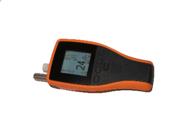
A portable dew point meter is a device used for dew point measurements and spot checks. It is characterized by its small size.

The weight of the product is approximately 200g to 400g for the sensor part, and less than 1kg to 3kg for the main unit combined.
Because of its ease of installation and maintenance, it is often used for spot checks to verify quality.

Depending on the product and the type of power source, the continuous operating time is 10 to 48 hours, which is long enough to withstand dew point measurements in the field.

Bench-mounted dew point meters are also produced in portable sizes, although they require a power supply.

Uses for Portable Dew Point Meters

Portable dew point meters are widely used for dew point measurements and spot checks.

They can be used in a wide range of environments, from general air, to low dew point process environments, to pressurized air.

They are often used for quality checks, especially in industrial processes:

  • Spot check of compressed air piping
  • Dryer performance checks
  • Spot control of dryer air
  • Measurement of various gases, such as nitrogen, argon, etc.
  • Spot control in industrial furnaces
  • Moisture measurement of gas shutoffs
  • Checking dryness of inert containers
  • Checking of high purity gas lines
  • Other monitoring and control of dryness in calibration rooms, laboratories, clean rooms, production plants, etc.

Principle of Portable Dew Point Meters

Since portable dew point meters are often used for fast spot check measurements in the field, many of them are easy to operate from sample connection to measurement.

Therefore, the sample connection can vary from an integrated type, a tube connection type, or a sensor type, all of which are characterized by their ease of use. In the case of the sensor type, the sensor part will be exposed, so it should be resistant to condensation.

There are two types of dew point measurement: the mirror-cooled type and the capacitance type.

In the mirror-cooled type, dew or frost forms on a small mirror inside the instrument when the sample gas is cooled and condenses.

This causes a change in the reflection and scattering of light on the mirror surface, and the dew point is measured by measuring the temperature at that time.

The capacitance method utilizes a capacitor with a layer of dielectric that reacts to the amount of moisture in the surrounding gas.

Ideally, the dielectric layer would absorb moisture at the same ratio as the surrounding moisture content, and this is used to detect the moisture content and determine the dew point.

Note that most portable dew point meters are capable of connecting to a PC and transferring data in order to handle measurement results efficiently.

Some can be connected to humidity probes or CO2 probes or can simultaneously measure temperature and humidity, and some have the ability to compensate for dew point fluctuations that depend on sample temperature changes by simultaneously measuring temperature.

カテゴリー
category_usa

Peltier Module

What Is a Peltier Module?

A Peltier module is a cooling device that uses a Peltier element, which is a thermoelectric element. Since it does not use refrigerant but only electricity for cooling, it is characterized by its low environmental impact.

A Peltier element is a semiconductor device that, when energized, generates a Peltier effect, causing a temperature difference between two surfaces. Generally, Peltier elements are lightweight and small plate-shaped, with a thickness of 2 mm to 5 mm.

The structure of a Peltier element consists of an n-type thermoelectric element, a p-type thermoelectric element, and electrodes sandwiched by a ceramic base.

Uses of Peltier Modules

The advantage of Peltier modules is that they are smaller than general cooling equipment and can be easily incorporated into equipment that requires cooling. Because of this advantage, they are used for cooling a wide variety of equipment.

Typical applications include cooling electronic equipment, such as computers and servers. They are especially useful in situations where there is a small cooling requirement or where heat sources are limited. For industrial equipment, they are also used in distribution boards and control panels.

Other applications include refrigerators, air conditioners, and dehumidifiers.

In recent years, Peltier coolers have also been commercialized as neck-mounted mobile coolers for heat control. There are also many smartphone coolers for smartphones that incorporate the functionality of peltier modules. They are also useful for cooling laser devices.

Cooling is essential for high-power laser devices such as laser diodes and fiber-optic lasers. Therefore, compact and motorized Peltier modules are used for cooling.

Principle of Peltier Modules

Peltier modules are made by laminating two different metals together. A potential difference is created between the two metals, and the Peltier effect is used to transfer heat from one metal to the other. The metals used are a combination of bismuth-based, silicon germanium-based, cobalt-tin-based, and iron-based.

The principle is that heat is transferred from the cooling plate to the heating plate by applying voltage to the Peltier element. Temperature can be controlled by the applied current. By reversing the polarity of the current, the cooling side and the heat-dissipating side can be reversed, making it possible to heat the object.

Since a large amount of heat is generated on the heat-dissipation side, water-cooling devices or heat sinks are often attached. There are also products with enhanced heat dissipation performance by sandwiching a heat-conductive material between the contacting surfaces.

On the heat-absorbing side, heat-absorption efficiency is maximized by attaching a cooling plate. Heat absorption efficiency is also increased by sandwiching a heat-conductive material between the contact surfaces with the cooling plate. However, the cooling temperature is limited to a minimum of 5°C.

How to Select a Peltier Module

Peltier modules can be sized according to the required capacity. In addition, products focused solely on cooling can be supplied at low and stable prices. High-performance products also exist and can be supplied with controls if precise operation is required.

Thus, the advantage of Peltier coolers is the ability to choose performance, price, and size according to the application. For consumer use, it is possible to focus on design improvements, while for industrial use, performance can be maximized to meet the required capacity.