カテゴリー
category_de

Nadelventil

Was ist ein Nadelventil?

Nadelventile sind Ventiltypen mit einem Schaft (Ventilschaft), der ein dünnes, spitzes Ende hat.

Nadelventile werden verwendet, um den Durchfluss in einem Durchflussweg zu steuern.

Sie zeichnen sich durch ihre Fähigkeit aus, die Durchflussmenge genau zu regeln, sowie durch ihre Funktion als Absperrventil zum vollständigen Öffnen und Schließen des Durchflussweges. Sie sind jedoch im Allgemeinen für relativ niedrige Durchflussmengen vorgesehen.

Anwendungen von Nadelventilen

Nadelventile werden aufgrund ihrer überragenden Fähigkeit, Durchflussmengen zu regulieren, häufig in Stromregelventilen eingesetzt, wo eine präzise Durchflusseinstellung erforderlich ist. Daher werden sie nur selten in der vollständig geöffneten Stellung verwendet, sondern meist durch Einstellen der Ventilöffnung und Fixierung auf den gewünschten Durchfluss.

Sie werden häufig zur Durchflussregelung in besonders kleinen Bereichen oder bei engen Durchflussregelbereichen eingesetzt. Normale Durchgangsventile (und einige Kugelventile) können den Durchfluss ebenfalls regeln, sind aber weniger präzise und die Feineinstellung ist schwierig, so dass sie im Allgemeinen für Durchflussregelungen verwendet werden, bei denen keine Präzision erforderlich ist.

Nadelventile hingegen können aufgrund ihrer speziell für die Durchflussregelung konzipierten Innenkonstruktion eine präzise und feine Durchflussregelung ermöglichen. Sie werden beispielsweise in der Halbleiterindustrie eingesetzt, um das Volumen der Stickstoffspülung zu regulieren, den Luftstrom zum Öffnen und Schließen von Luftzylinderventilen und Membranventilen zu steuern und als Absperrventile für Manometerflüssigkeiten.

Funktionsweise von Nadelventilen

Der Aufbau eines Nadelventils besteht aus einem Gehäuse (Ventilkasten), einer Spindel (Ventilschaft) und einem Griff.

Das Hauptmerkmal von Nadelventilen ist, dass der Ventilkegel, wie der Name schon sagt, nadelförmig ist. Durchgangsventile ähnlicher Bauart haben einen sehr großen Ventilkegel und eignen sich hervorragend zum Schließen, aber nicht zur Durchflussregelung.

Bei Nadelventilen hebt sich der Ventilkegel (Nadel) am Ende der Spindel, wenn der Griff zum Öffnen des Ventils gedreht wird, und die Kanalöffnung zur Sitzseite ändert sich allmählich. Die Durchflussmenge ändert sich daher nur geringfügig, so dass die Durchflussmenge leicht und präzise eingestellt werden kann.

Nadelventile können als Absperrventile verwendet werden. Nadelventile sind jedoch nicht für einfache Absperrungen geeignet, da die Ventilspindel mehrmals gedreht werden muss, um sie vollständig zu öffnen und zu schließen.

Um die Flüssigkeit vollständig und einfach abzusperren, wird ein Absperrventil, z. B. ein Durchgangsventil oder ein Kugelventil, in den Durchflussstrom eingebaut.

Arten von Nadelventilen

Nadelventile gibt es in den folgenden Ausführungen:

  • Typ Öffnen/Schließen
    Manuell oder automatisch (elektrisch betätigt oder magnetisch gesteuert)
  • Art des Rohranschlusses
    Mit Gewinde (konische Rohrgewinde Rc, NPT, usw.), Flansch, Ringverbindung, usw.

Automatische Nadelventile werden dort eingesetzt, wo das Öffnen, Schließen und Einstellen des Durchflusses durch Fernsteuerung erforderlich ist. Ein elektrischer Antrieb oder ähnliches wird verwendet, um den Kegel und die Spindel zum Öffnen und Schließen des Ventils zu drehen.

Einige Typen verwenden einen Schrittmotor als Antriebsmotor, der eine genaue und feine Steuerung ermöglicht. Schrittmotoren sind Motoren, die den Drehwinkel mit Hilfe von Impulssignalen steuern können und eine Art von Motoren sind, die eine hohe Positioniergenauigkeit gewährleisten.

Weitere Informationen über Nadelventile

Werkstoffe für Nadelventile

Typische Werkstoffe (Gehäuseteile), die für Nadelventile verwendet werden, sind:

  • Messing
  • Rostfreier Stahl

Messingwerkstoffe eignen sich für allgemeine Anwendungen und werden häufig für Anwendungen mit niedrigem Druck, ohne Druck, mit geringem Durchfluss wie Luft, Kalt- und Warmwasser, Öl usw. verwendet. Werkstoffe aus rostfreiem Stahl werden z. B. für Gasleitungen für Silan und Stickstofftrifluorid verwendet, die häufig in der Halbleiterindustrie eingesetzt werden.

カテゴリー
category_de

Nylonschlauch

Was ist ein Nylonschlauch?

Nylonschläuche sind Schläuche, die aus Nylonharz hergestellt werden und in erster Linie für Sanitärzwecke bestimmt sind.

Sie werden in einer Vielzahl von Branchen für Flüssigkeiten wie Luft, Wasser und Schmiermittel verwendet. Zu den Vorteilen gehören die hervorragende Flexibilität, die eine einfache Verarbeitung ermöglicht, und die niedrigen Kosten.

Je nach Produkt weist das Nylonmaterial eine ausgezeichnete Beständigkeit gegen Druck, Hitze, Chemikalien, Öl, Vibrationen und Korrosion auf.

Anwendungen von Nylonschläuchen

Nylonschläuche werden für Schmier-, Pneumatik-, Hydraulik- und andere Rohrleitungsanwendungen als Alternative zu herkömmlich verwendeten Rohren aus Kupfer und anderen Materialien eingesetzt. Insbesondere können Nylonschläuche in Öl- und Pneumatikanlagen, Zentralschmieranlagen, Beschichtungsanlagen und chemischen Anlagen verwendet werden.

Nylonschläuche können auch für Rohrleitungen in engen Räumen oder bei komplexen Strömungslinien verwendet werden, indem die hervorragende Flexibilität von Nylon genutzt wird. Zu den anderen Nylonarten gehören flexiblere Typen, die in oszillierenden Abschnitten verwendet werden können, und spezielle Nylontypen, die speziell für hohen Druck und chemische Beständigkeit ausgelegt sind.

Funktionsweise von Nylonschläuchen

Wie Faserwerkstoffe sind Nylonschläuche dehnungs- und schrumpfungsbeständig und weisen eine hohe Abriebfestigkeit und Zähigkeit auf. Außerdem sind sie sehr hitze-, stoß- und chemikalienbeständig. Das zuerst entwickelte 6,6-Nylon war die erste synthetische Faser der Welt, die in großem Umfang verwendet wurde. Heute werden Polyamide gemeinhin unter dem Begriff Nylon zusammengefasst.

Nylonprodukte selbst werden in der Regel aus 6-Nylon oder 6,6-Nylon hergestellt, für Nylonschläuche wird jedoch häufig Nylon 11 oder Nylon 12 verwendet. Der Grund dafür ist, dass Nylon 11 und Nylon 12 widerstandsfähiger gegen Stöße usw. und Temperaturschwankungen sind.

Die Zahlen in diesen Bezeichnungen leiten sich von der Anzahl der Kohlenstoffatome im Monomer-Rohstoff ab, der zur Herstellung von Nylon verwendet wird. Weiche Schläuche werden mit Weichmachern hergestellt, um die Flexibilität zu erhöhen, während starre Schläuche ohne Weichmacher als starres, nicht weichgemachtes Nylon bezeichnet werden. Es können auch andere Arten von Nylon verwendet werden, z. B. Nylon, das durch Verarbeitung verstärkt wurde.

Auswahl eines Nylonschlauchs

Nylonschläuche unterscheiden sich je nach Produkt in ihrer Druckfestigkeit, Hitzebeständigkeit und Flexibilität. Es ist wichtig, das Produkt zu wählen, das für Ihre Anwendung am besten geeignet ist.

1. Flexible Nylonschläuche

Die Flexibilität des Schlauches hängt davon ab, ob ein Weichmacher verwendet wird oder nicht. Weiche Nylonschläuche enthalten Weichmacher und sind hochflexibel. In Bezug auf Druck- und Hitzebeständigkeit ist die Leistung etwas geringer als bei nicht weichgemachtem Nylon, aber einige Produkte sind für hohen Druck geeignet. Darüber hinaus besteht kein Unterschied darin, dass der Hauptbestandteil Nylon ist, so dass die Leistung nicht wesentlich schlechter ist.

Durch den Weichmacher können sich jedoch im Harz enthaltene niedermolekulare Substanzen, so genannte Monomere und Oligomere, auf der Schlauchoberfläche absetzen und wie weißes Pulver an ihr haften. Im Allgemeinen gibt es keine Leistungseinbußen in Bezug auf Druckfestigkeit, chemische Beständigkeit usw., aber es besteht die Tendenz, dass die Flexibilität in Zukunft abnimmt.

2. Nylonschläuche ohne Weichmacher

Nylonschläuche ohne Weichmacher sind die härtesten Nylonschläuche. Sie haben auch die höchste Druck- und Hitzebeständigkeit und können bei hohem Druck und hohen Temperaturen verwendet werden.

Einige Produkte können farblich gekennzeichnet werden, indem für jeden Schlauch eine andere Farbe gewählt wird, und sind in verschiedenen Farben erhältlich. Schwarz ist jedoch in Bezug auf die Witterungsbeständigkeit überlegen, weshalb einige Hersteller schwarze Schläuche empfehlen, wenn keine besondere Auswahl erforderlich ist.

Wenn Chemikalien als Flüssigkeiten verwendet werden sollen, muss vor der Verwendung geprüft werden, ob die Schläuche gegen die verwendeten Chemikalien beständig sind.

カテゴリー
category_de

Bohrreibahle

Was ist eine Bohrreibahle?

Eine Bohrreibahle ist ein Werkzeug, das Bohren und Reiben in einem einzigen Arbeitsgang ausführen kann.

Normalerweise muss nach dem Bohren des Lochs das Reiben (Nachbearbeitung zur Vorbereitung des Lochdurchmessers und der Oberflächenrauheit) separat durchgeführt werden, was bedeutet, dass das gleiche Loch zweimal gebohrt werden muss. Durch den Einsatz einer Bohrreibahle kann jedoch gleichzeitig gebohrt und gerieben werden, wodurch sich die Bearbeitungszeit erheblich verkürzt.

Die Konstruktion der Bohrreibahlen ist einzigartig. Die Spitze der Bohrreibahlen ist bohrerförmig und wird von der Mitte bis zur Basis der Schneide aufgerieben. Dank der Form der Bohrreibahle können zwei Arbeitsgänge gleichzeitig durchgeführt werden.

Anwendungen von Bohrreibahlen

Bohrreibahlen werden zum Bohren von Löchern verwendet, bei denen eine höhere Präzision erforderlich ist. Bei der Bearbeitung von Gussformen beispielsweise wird der Abstand zwischen Gussform und Stempel, der das Zentrum der Gussform bildet, auf 1/100 Zentimeter genau eingestellt, um sicherzustellen, dass die Gussform nach wiederholtem Zusammenbau in der gleichen Position eingebaut wird.

Für die Löcher, in die die Passstifte eingesetzt werden, werden Bohrreibahlen verwendet. Es ist Vorsicht geboten, denn wenn die Löcher nicht genau sind, können die Positionierstifte beim Einschlagen falsch ausgerichtet werden, wodurch Stempel und Gussform falsch ausgerichtet und im schlimmsten Fall beschädigt werden.

Bohrreibahlen werden zum Bohren von Löchern verwendet, die eine genaue Positionierung erfordern, sowie zur Bearbeitung der Passungstoleranzen von Präzisionsteilen. Es ist daher zu erwarten, dass die Verwendung von Bohrreibahlen in Bereichen, in denen hohe Präzision erforderlich ist, wie im Präzisionsmaschinen- und Formenbau, weiter zunehmen wird.

Funktionsweise von Bohrreibahlen

Bohrreibahlen sind Werkzeuge, die zur Steigerung der Arbeitseffizienz entwickelt wurden. Sie bohren gleichzeitig das Loch und reiben den Lochdurchmesser auf, indem sie die Seiten des Lochs schaben. Dies bedeutet, dass das Bohren und die Endbearbeitung in einem einzigen Arbeitsgang erfolgen können.

Das Werkzeug hat sowohl eine Schneidkante zum Bohren als auch eine Schneidkante zum Reiben. Die vordere Schneide (10-30 mm) ist die Bohrschneide und die hintere Schneide ist die Reibschneide, mit einem Reibahlenaufmaß von 0,1-0,5 mm.

Eine Bohrreibahle mit einem Fertigmaß von 8 mm hat beispielsweise eine Nenngröße von 8 mm, einen Bohrdurchmesser von 7,7 mm, einen Reibdurchmesser von 8 mm, eine Bohrerschneidenlänge von 22 mm und eine Gesamtschneidenlänge von 80 mm. Der Schnittwinkel der Schneide zum Aufbohren wird im Allgemeinen zwischen 15 ° und 45 ° eingestellt. Der Spanbrecher schneidet auch die Späne, was einen reibungslosen Abtransport der Späne und eine verbesserte Reibgenauigkeit gewährleistet.

Für Bohrreibahlen wird hauptsächlich HSS-Stahl verwendet, von dem einige zur Verbesserung der Haltbarkeit mit TiCN beschichtet sind. Dies gewährleistet eine lange Lebensdauer und eine hohe Bearbeitungsgenauigkeit.

Arten von Bohrreibahlen

Es gibt drei Haupttypen von Bohrreibahlen: Bohrreibahlen mit gerader Spannut, Bohrreibahlen mit Spiralnut und typgerechte Bohrreibahlen.

1. Bohrerreibahlen mit gerader Spannut

Bohrreibahlen mit gerader Spannut sind Bohrreibahlen mit einer geraden Schneidrille. Sie eignen sich für die Bearbeitung allgemeiner metallischer Werkstoffe und von Kunststoffen und werden eingesetzt, wenn eine hohe Genauigkeit des Bohrungsdurchmessers und eine hohe Oberflächenrauhigkeit erforderlich sind.

Außerdem verbessern sie die Effizienz der Bearbeitung aufgrund ihrer geringen Schnittkraft und der gleichmäßigen Spanabfuhr.

2. Bohrerreibahlen mit Spiralnut

Bohrerreibahlen mit Spiralnut haben spiralförmig verlaufende Nuten. Diese Struktur erleichtert die reibungslose Spanabfuhr und eignet sich für Tieflochbohrungen und die Bearbeitung von schwer zu bearbeitenden Werkstoffen. Sie unterdrückt außerdem Vibrationen und verbessert die Oberflächengüte der bearbeiteten Fläche.

3. Typgerechte Bohrreibahlen

Typgerechte Bohrreibahlen sind maßgeschneiderte Bohrreibahlen, die für bestimmte Teile und Anwendungen entwickelt wurden. Sie ermöglichen das Bohren von Löchern mit speziellen Formen und Größen und arbeiten mit einem hohen Maß an Präzision und Effizienz. Sie reduzieren außerdem die Arbeitszeit und die Kosten, indem sie mehrere Verfahren in einem einzigen zusammenfassen.

カテゴリー
category_usa

Hydraulic Damper

What Is a Hydraulic Damper?

Hydraulic Dampers

A hydraulic damper is a device that absorbs vibration and shock through hydraulic pressure. They are used in vehicles and building structures. They are also sometimes called shock absorbers.

Hydraulic dampers allow for flexible adjustment through the control of hydraulic pressure. By varying the oil flow and pressure in the damper, the control characteristics of vibration and shock can be adjusted.

This allows them to respond to a wide variety of situations and requirements. They are generally durable and provide stable performance over a long period. If properly maintained, they have a long service life.

However, each hydraulic damper product has certain usage ranges and limitations. Care should be taken not to exceed the recommended maximum load or pressure. Excessive loading or use under conditions outside the operating range may cause damper failure or reduced effectiveness.

Uses for Hydraulic Dampers

Hydraulic dampers are widely used in a variety of applications. The following are examples of typical applications:

1. Automobiles

Hydraulic dampers are often used in automobile suspensions. They absorb vibrations and shocks from the vehicle body and improve ride comfort. They can be adjusted to the appropriate damping force in response to various road conditions.

2. Vibration Control Devices

They are often used as vibration control devices for building structures and bridges. They absorb external forces such as earthquake and wind, and serves to control vibration of the structure and ensure its stability. This can improve the seismic resistance and safety of structures.

3. Industrial Machinery and Equipment

They are often used to control vibration and shock in industrial machinery and equipment. They are utilized to control the vibration of conveyor belts and to absorb shocks during large machine operations.

Principle of Hydraulic Dampers

The basic principle of hydraulic dampers is based on the turbulent resistance of fluid. Turbulent resistance is the principle that resistance increases in proportion to fluid velocity.

A hydraulic damper consists of a cylinder, a piston, and hydraulic oil. In most cases, the cylinder is filled with hydraulic oil. When pressure is applied to the piston rod, the rod pushes the hydraulic oil filled in the cylinder.

There is a small space between the cylinder and the piston, and the hydraulic oil flows into this void. This flow of hydraulic oil creates resistance and dampens shocks. Vibration and shock are often absorbed as thermal energy of the hydraulic fluid.

By adjusting the width and number of voids, the cushioning characteristics of hydraulic dampers can be changed to suit the object. When incorporated into seismic isolation and vibration control mechanisms of buildings, quantities are required to ensure adequate functionality.

Types of Hydraulic Dampers

There are two types of hydraulic dampers: monotube and twin-tube.

1. Monotube

A monotube damper is a hydraulic damper that consists of a single inner and outer tube. The inner tube functions as a damper cylinder with a piston inside. The outer tube houses the piston rod and covers the damper cylinder.

The piston inside the inner cylinder can control the flow of oil, enabling a higher level of damping characteristics. This improves responsiveness and control accuracy. In addition, the outer cylinder effectively dissipates heat from the oil, making it easier for damper performance to remain stable over long periods of operation.

Due to its high control performance and heat dissipation capability, it is often used in suspensions for sports cars and high-performance vehicles.

2. Twin-Tube

A twin-tube damper is a hydraulic damper consisting of two tubes, an inner tube and an outer tube. The inner tube serves as the main damper chamber and has a piston inside. The outer tube functions as a reservoir tube that houses the oil.

Twin-tube dampers are characterized by lower manufacturing costs than mono-tube dampers. They are also relatively lightweight, making it possible to reduce the weight of the vehicle. Because of these features, these hydraulic dampers are widely used in mass-market and general-purpose vehicles.

カテゴリー
category_usa

General-Purpose CAD

What Is General-Purpose CAD?

General-Purpose CAD is a type of CAD that can be used for a wide range of design work without specializing in a particular field.

CAD is an acronym for “Computer Aided Design” and is a design support tool. CAD has been used in a wide range of fields, as it has improved the efficiency of drafting by hand in the age without computers, which can now be done on a monitor. General-Purpose CAD, as the name implies, is software that can be used in a variety of fields.

It has the basic functions for drafting and design. General-Purpose CAD is not only available as paid commercial software, but also as free software. The disadvantage of free software is that it is not costly, but it has limitations such as limited functionality, no support, and the need to do everything on one’s own.

On the other hand, there are many types of specialized CAD software available, with software optimized for different fields, such as for electrical design or mold design.

Uses of General-Purpose CAD

General-purpose CAD is used in a wide range of fields because of its basic design and drafting functions. Below are some examples of applications in various industries.

1. architectural and civil engineering industries

General-Purpose CAD is used for architectural design, urban planning, and civil engineering work.

2. interior design industry

In the interior design industry, General-Purpose CAD is used to generate drawings of building interiors designed by interior coordinators and interior designers. It is also useful in determining the layout of rooms and the placement of interior furnishings.

3. machinery industry

The machinery industry uses General-Purpose CAD to design aircraft, automobiles, robots, screws, and other machine element parts.

4. welfare industry

In the welfare industry, General-Purpose CAD is mainly used to design barrier-free and welfare facilities. Some people working in the welfare industry have qualifications such as welfare housing environment coordinators.

Characteristics of General-Purpose CAD

General-Purpose CAD is often less expensive than specialized CAD, and many software packages are available for free. General-Purpose CAD, while useful, is relatively expensive, requiring several hundred thousand yen to install.

In many cases, since General-Purpose CAD is sufficient to cover basic functions, a dedicated CAD system is not necessary if you only need to check, edit, and print drawings or if you are dealing with drawings that make extensive use of specialized parts.

Other Information on General-Purpose CAD

Differences between 2D and 3D CAD

There are two types of CAD: 2-D CAD and 3-D CAD. The characteristics of each are as follows.

1. 2D CAD
This type of CAD is used for designing on a flat surface and is used to create drawings for housing construction and machinery and equipment. In recent years, demand for 3D CAD, which enables three-dimensional design, has increased, but 2D CAD is still in demand.

2. 3D CAD
3D CAD is a CAD system for designing in a three-dimensional space. Although it is more expensive than 2D CAD, it can do a lot of things, so it is in high demand.

By saving the designed model, a data file is created. Since the CAD used at this time differs from person to person, it is necessary to save the data in a compatible file format (intermediate file) when exchanging data.

The following formats are available for intermediate files.

  • STEP format
    This is an internationally standardized format.
  • IGES format
    This format is specified in the U.S. and is often used for automotive applications.
  • SIMA format
    This is a format specified in Japan and is often used for surveying applications.

Intermediate files are not completely compatible, and for complex shapes, there may be some geometry discrepancies depending on the CAD system used.

カテゴリー
category_usa

Vibration Analysis Software

What Is Vibration Analysis Software?

Vibration analysis is used to determine the natural frequencies of structures. The target structures can be electrical appliances, automobiles, steel bridges, and many other types of structures. Vibration analysis software can simulate the forces, deformations, and breakdowns caused by vibration.

Vibration analysis functions are incorporated into structural analysis software as linear dynamic analysis. There is also a device that processes experimental data called sound and vibration analysis software, but this section describes vibration analysis software as simulation software.

Uses of Vibration Analysis Software

Vibration analysis software is used for various structures that generate vibration.

Since each structure has its own natural frequency, if the applied vibration matches the natural frequency, a resonance phenomenon is caused. Since this resonance causes increased vibration and damage or destruction of the structure, it is necessary to check for resonance using simulation at the design stage. Vibration analysis software is used to confirm such phenomena.

Principles of Vibration Analysis Software

Vibration analysis is divided into two categories: modal analysis, which studies the eigenvalues of a structure’s vibration, and frequency response analysis, which examines the response to external vibrations.

The modal analysis focuses on the frequency of an object when no external force is applied (free vibration). The natural frequencies of the object are calculated, and measures can be taken to avoid resonance frequencies that increase vibration.

Frequency response analysis focuses on the response of an object when an external force is applied at a specific frequency. When an object continues to vibrate at a certain frequency and amplitude, it is in a steady state with no time variation. Frequency response analysis evaluates periodic vibration in a steady state.

In addition to simulation, vibration analysis software outputs various vibration parameters from the object’s time series data using FFT and tracking analysis. The frequency components can be obtained by Fourier transform.

Characteristics of Vibration Analysis Software

Vibration analysis software simulates how a structure changes in response to externally applied, cyclic forces, and outputs the results through visualization and other means. When a constant force is applied to the object and the stresses and deformations that occur are examined, it is called a linear static analysis.

Vibration analysis software calculates the equations of motion, including springs, dampers, and masses. This is similar to solving for the vibration of a weight connected to a spring, but the equations used in vibration analysis software are more complex because they move in three directions and take rotation into account.

When conducting vibration analysis, the target structure is often divided into smaller elements, and equations of motion are created for each element. Each of the countless elements has its own equation, and a computer is used to solve all of them. For accurate simulation, the number of elements must be increased. For this division of elements, the finite element method is often used for structural analysis, such as vibration analysis.

カテゴリー
category_usa

Microfabrication Machine

What Is a Microfabrication Machine?

A microfabrication machine is a processing machine that performs micron-level microfabrication. They are not limited to processing metals, but also process resins, polymers, and inorganic materials.

In recent years, there are cutting machines that can be programmed and controlled at the 10-nm level, and the scale of microfabrication is advancing daily.

Microfabrication machines in the broad sense of the term also include electric discharge machines, wire EDMs, jig borers, and laser cutting machines. In handling these microfabrication machines, temperature control such as room temperature and operator skill are also very important.

Uses of Microfabrication Machines

In recent years, microfabrication technology has become necessary in all industrial fields and is used in a wide range of applications.

In the semiconductor and electronic components industries, it is essential for processing package molds and various parts as devices become finer and finer, and in the medical equipment industry, it is essential for parts with micro flow paths such as biochips and parts with fine electrode structures.

It is possible to realize microstructures that cannot be machined with conventional end mills, such as heat dissipating fins with extremely small pitch, holes with micron-order pitch, and projection array structures with submicron-order pitch.

Principle of Microfabrication Machines

Microfabrication machines, in the broad sense, encompass multiple types of machines, but there are three representative types of machines. There are microfabrication machines, electrical discharge machines, and wire EDM machines, each of which has different principles.

1. Microfabrication NC Machine

Although the basic structure and principles are much the same as those of conventional NC machining centers, high-precision control is applied to all aspects of the machine, including the drive method for each axis, coolant temperature control, and rotation speed control.

Linear motors are used to drive each axis, and some products have a programmed resolution of 0.1 nm. Hydrostatic guiding is used for the guides that control the reciprocating motion, which enables infinitely low frictional resistance and high motion accuracy.

Coolant, which manages the heat generated during processing, is temperature-controlled at the 1/100°C level, and to block various vibrations transmitted from outdoors, anti-vibration measures are taken from the building foundation structure, or the building is installed on a vibration isolation system. In addition, the coolant is installed in a constant-temperature room to prevent thermal expansion of the equipment.

2. Electrical Discharge Machining Center

For microfabrication of conductive materials, an electric discharge machine with an anode connected to the material side and a cathode connected to the movable electrode is used. This technology of machining with direct current is used for materials and shapes that are susceptible to machining strain from cutting and polishing, and enables higher precision and surface roughness through repeated machining.

3. Wire Electric Discharge Machine

The basic principle is the same as that of EDM, but a cathode is connected to a very thin wire of about 0.05 to 0.3 mm, and a DC current is applied between the wire and the material to cut the material. Processing is performed in water with controlled conductivity, and the wire is constantly fed during processing. Since the cutting is done in a non-contact, stroke-by-stroke manner, no processing stress is generated. It is possible to cut a wire thickness plus 20 to 30 microns.

Other Information on Microfabrication Machines

Machines Used in Combination With Microfabrication Machines

Machines used in combination with microfabrication machines require a high degree of precision and stability. In order to support microfabrication, the machine itself must be highly accurate and the machining conditions must be set appropriately. It is necessary to understand the characteristics of each machine and select the optimum machine.

Here, we introduce three types of typical machines used in conjunction with microfabrication machines: laser cutting machines, electron beam machines, and ion beam machines.

  1. Laser Processing Machine
    Laser processing machines cut and process materials by irradiating high-energy laser beams. They are suitable for microfabrication and can be used for a variety of materials, both metallic and non-metallic. They are also highly accurate and can handle minute processing.
  2. Electron Beam Machine
    Electron beam machines cut and process materials by irradiating heated electron beams at high speed. They are suitable for microscopic processing and are used in fields that require high processing accuracy.
  3. Ion Beam Machines
    Ion beam machines can perform microfabrication and surface modification of material surfaces by irradiating ion beams. This is especially effective for hard materials such as ceramics and glass.
カテゴリー
category_usa

Micro Current Meter

What Is a Micro Current Meter?

A Micro Current Meter is a device that measures tiny currents, such as nanoamperes and picoamperes. It is also called a multimeter or picoammeter.

With advances in electronic device technology, circuits have become smaller and more energy-efficient, and the currents in circuits have become tiny, less than microamperes. With ordinary ammeters, it is difficult to detect very small currents due to noise and other effects generated during measurement. Micro current meters, however, are designed to minimize the effects of such noise, making it possible to quantify small currents.

Uses of Micro Current Meter

Micro Current Meters Are Used in Electrical Circuits, Mainly in Small Circuits

Micro current meters are used to measure current values in electronic circuits, for example, in highly integrated and miniaturized circuits, such as amplifiers and communication circuits. Some devices are capable of measuring up to femtoamperes.

Micro Current Meters Can Also Be Integrated Into Production Lines

Some micro current meters have a sampling speed of 1000 times/second and can be integrated into production lines. Such Micro current meters are also used for go/no go testing of electronic components.

In addition, micro current meters are sometimes used to detect leakage current in diodes.

Principle of Micro Current Meters

Be Careful of Noise When Using a Micro Current Meter

Micro current meters are capable of measuring currents as small as nanoamperes and picoamperes up to about 1A. When measuring microcurrents, it is necessary to eliminate noise sources as much as possible. Although the Micro current meter itself is designed not to be affected by noise, the resistance of the sample, the power supply, and the temperature of the environment in which it is installed are also factors that can cause noise, so it is necessary to pay attention to the effects of noise originating from the measurement object.

Micro Current Meters Can Detect Small Currents, but Be Careful Not to Allow Excessive Currents to Flow

Some micro current meters are combined with an ultra-high resistance meter. Such devices can also be used as electrometers. Micro current meters that prioritize sampling speed or noise reduction are also available. Note that the error in the measured value is relative to the measured value, so it is not always possible to measure with nanoamperes of accuracy, and the absolute value of the error varies depending on the measured value. Also, care must be taken not to apply excessive current during measurement, as applying a current above the upper limit of the device may damage it.

カテゴリー
category_usa

Circulating Filtration Device

What Is a Recirculating Filtration System?

Circulating Filtration Devices

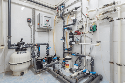
A recirculating filtration system is a system that filters tap water and circulates the filtered water. Recirculating filtration systems are divided into two types according to their function: physical filtration systems and biological purification systems.

Physical filtration systems are used to remove fine particles, hair, fibers, and other foreign substances that are not dissolved in water. Biological purifiers use filter media such as activated carbon as a support, in which microorganisms are grown. This type of system has almost no physical filtration function, but the microorganisms are able to decompose pollutants in the water.

Uses of Recirculating Filtration Systems

Recirculating filtration systems can maintain and purify water quality through physical filtration or biological purification. They are therefore used in places where water quality must be kept constant or where water consumption must be reduced.

Principle of Recirculating Filtration Systems

When water to be filtered is passed through a porous filter material, substances larger than the holes in the filter material are collected, and only substances smaller than the holes are passed through. This is how filtration equipment removes foreign substances from water.

There are three main types of filtration systems: sand filtration, diatomaceous earth filtration, and cartridge filtration.

Sand filtration is a filtration method that uses sand or gravel as the filtering material. Natural sand and anthracite are used, and substances down to several tens of micrometers can be removed. It is widely used because of its various advantages, such as its ability to cope with a certain degree of water quality fluctuation and the stable quality of treated water.

Diatomaceous earth filtration is a filtration method that uses diatomaceous earth as a filter aid. It has the highest removal capacity of the three, but is considered difficult to maintain.

Cartridge filtration is a filtration method that uses cartridge-type filter media. Synthetic fiber or polyester is used as the cartridge material, which can remove substances of 10-15 µm in size. Cartridges are consumables, so running costs are relatively high.

カテゴリー
category_usa

Quantitative Filling Machine

What Is a Quantitative Filling Machine?

Quantitative Filling Machines

A quantitative filling machine is a filling machine that can measure and fill a certain amount of product using a scale. There are liquid filling machines and solid filling machines. However, the mechanism for measuring weight using a scale is largely the same.

There are two types of quantitative filling machine: automatic filling machines and semi-automatic filling machines. Automatic filling machines are those in which filling containers flow through a conveyor line and start filling automatically when they reach a certain position. On the other hand, a semi-automatic filling machine automatically goes from the conveyor line to the filling location, but the filling start operation is done manually.

Uses of Quantitative Filling Machines

Quantitative filling machines are used by many manufacturers. For example, they are used for liquids, such as water or oil. These are filled using head pressure from a pump or tank.

Other semi-solid items, such as sauce and pastes, can also be filled. In such cases, a screw is installed in the tank to prevent blockage.

For items of irregular size, such as vegetables and fruits, several weighing scales are used to weigh several items at once. The bag is then filled by selecting the right weight for each item.

Principle of Quantitative Filling Machines

Liquid quantitative filling machines fill liquids from tanks or hoppers. The liquid is filled from the tank or hopper through piping to the filling nozzle. When the filling process is started, the nozzle valve opens, and the liquid begins to fill. When the amount of liquid is reached, the weigher sends a signal to stop the filling process.

Weighing instruments often use load cells. Load cells can convert the force caused by a load into an electrical signal. Load cells have a strain gauge, an electrical resistance wire strain gauge, attached to a metal body and measure the change in resistance. Compared to conventional spring-loaded load cells, these load cells are extremely accurate.