カテゴリー
category_usa

Linear Guide Rail

What Is a Linear Guide Rail?

A linear guide rail is a rail-like structure used to attach sensors or other devices, commonly found in industrial and automation applications. These rails feature holes or slots for easy mounting and are known for their ease of replacement and maintenance. Wiring can be conveniently routed along the rails for a cleaner appearance.

Linear guide rails adhere to standardized specifications, allowing compatibility with a wide range of manufacturers and devices. It is important to consider the electrical characteristics and requirements of the devices being mounted, including proper isolation and grounding.

Uses of Linear Guide Rails

Linear guide rails have diverse applications:

1. Industry

Used in automation and control systems, linear guide rails support the installation of various sensors and devices. In production lines, they can hold position and temperature sensors for process monitoring and control. These devices work in conjunction with controllers to facilitate automated processes.

2. Security

Linear guide rails play a crucial role in security systems, supporting equipment like surveillance cameras. They also mount motion sensors and door access controls, enhancing security by detecting unauthorized entry or movement.

3. Building Management Systems

In building management systems, linear guide rails are used for environmental monitoring. They support lighting and light sensors in lighting control systems and can hold temperature and humidity sensors for maintaining comfortable environments and improving energy efficiency.

Principle of Linear Guide Rails

Linear guide rails provide a standardized structure for positioning sensors and devices. They are typically made from lightweight and cost-effective materials like aluminum, although stainless steel is preferred for corrosion resistance. Rails can be cut to required lengths and feature holes or slots for mounting sensors or devices.

Types of Linear Guide Rails

Various types of linear guide rails include:

1. Flange Parallel Type

This type has a parallel flange at the top, providing space for sensor mounting, and is suitable for horizontal placements.

2. Orthogonal Flange Type

Featuring a flange protruding at a right angle at the top, this type is used for perpendicular mounting, useful in tight spaces or complex arrangements.

3. Straight Type

A straight rail without a top flange, this type is ideal for simple, straight-line arrangements or when a high density of sensors and devices is required.

カテゴリー
category_usa

Wave Springs

What Is a Wave Spring?

Wave springs are coiled springs with a unique corrugated shape. Compared to standard coil springs, they are more compact and capable of storing more elastic energy within the same length. Primarily used for supporting objects and absorbing vibration, wave springs are well-suited for space-constrained environments. Additionally, their lightweight design contributes to weight reduction in various applications.

Their ability to absorb vibration reduces the transmission of vibration and shock to objects, enhancing the durability of products and machinery. Easy to assemble and disassemble, wave springs offer significant design flexibility. However, it’s important to note that stress concentration in the waveform can affect the spring’s life and strength, which should be mitigated through proper materials and design.

Uses of Wave Springs

Wave springs find applications in various industries, including:

1. Automobiles

In the automotive sector, they are used to adjust the tension of seats and seat belts, enhancing passenger comfort and safety. They also support door-opening and closing mechanisms.

2. Home Appliances

Wave springs are utilized in home appliances like refrigerators, washing machines, and ovens for smooth opening and closing actions. They also absorb vibrations and noise from motors and other components, improving the quietness of these appliances.

3. Fishing Reels

In fishing reels, wave springs assist in controlling spool rotation and line winding, enabling smooth casting and retrieval.

Principle of Wave Springs

The principle of wave springs lies in the accumulation and release of elastic energy. When compressed or extended by an external force, they store or release energy. The interaction between the waveforms, with alternating peaks and troughs, ensures even distribution of the deformation effect.

How to Select Wave Springs

Key considerations when selecting wave springs include:

  • Diameter: Choose the appropriate wire thickness based on the required strength and maximum load.
  • Free Length: Ensure the spring’s uncompressed length matches the operational range and fits correctly in the equipment.
  • Material: Select a material that offers the necessary performance and durability, considering factors like the operating environment and corrosion resistance.
  • Maximum Load: Choose a spring that can handle the expected operational load without risk of deformation or damage.
カテゴリー
category_usa

UHMWPE

What Is UHMWPE?

UHMWPE, standing for ultra-high molecular weight polyethylene, is a high-density polyethylene variant noted for its excellent durability. It’s known for high abrasion resistance and chemical resistance, making it a widely used material in various industries.

UHMWPE, sometimes referred to as UHMW or NuLite (a trade name), is essentially the same substance, with variations in naming due to abbreviations or branding.

Uses of UHMWPE

Chemical Industry:

    UHMWPE is extensively used as a piping material in the chemical industry due to its superior chemical resistance. It’s suitable for transporting and storing corrosive liquids and solvents and is also used in manufacturing components like pump parts and valve seats.

  • Food Industry: Its high chemical resistance and antimicrobial properties make UHMWPE valuable in the food industry, used in liquid transportation, containers, and packaging materials.
  • Medical Devices: Leveraging its antibacterial properties, smoothness, abrasion resistance, and safety for human contact, UHMWPE is utilized in creating surgical tools, artificial joints, and implants.
  • Energy Industry: UHMWPE is used in the energy industry as a lining material for oil pipes and as an insulating material for electrical wiring, thanks to its chemical and abrasion resistance and electrical insulation properties.
  • Sports and Outdoor Activities: Its strength and lightweight make UHMWPE a popular choice for manufacturing sports equipment, tents, and mountaineering gear.

Characteristics of UHMWPE

  • Durability: UHMWPE is renowned for its exceptional impact and abrasion resistance, surpassing that of nylon resin.
  • Chemical Resistance: It resists a wide range of chemicals, is non-toxic, and is safe for human contact, making it suitable for food processing and packaging.
  • Wide Temperature Range: UHMWPE operates effectively across a broad temperature spectrum, from high temperatures up to about 80°C to low temperatures down to about -100°C. Its low water absorbency makes it ideal for water-involved applications.

Types of UHMWPE

  • Sheet Type: UHMWPE sheets are used in chemical plants and industrial machinery parts due to their abrasion and chemical resistance.
  • Pipe Type: UHMWPE pipes are crucial in the transport and storage of corrosive liquids, and are also used in the food industry and medical applications.
  • Fibrous Type: Fibrous UHMWPE is utilized in bulletproof vests, cutting tools, and wear-resistant parts due to its high strength and durability.
  • Film Type: Film UHMWPE is used as an insulating material in electronics and electrical components, as well as in high-temperature environments.
カテゴリー
category_usa

Inspection Glove

What Is an Inspection Glove?

Inspection Gloves

Inspection Gloves: Reducing Contamination Risk

Inspection gloves are utilized for quality control and precision tasks. Unlike regular gloves that may shed fibers, lint, and other debris, inspection gloves are employed in environments where cleanliness is paramount, such as precision parts manufacturing and painting, to prevent foreign materials from contaminating products.

Key Features of Inspection Gloves

Inspection gloves are designed to provide a snug fit for the hands and offer excellent fingertip dexterity, facilitating detailed work. Some varieties, like antistatic gloves, are specifically designed for use with electronic components and other static-sensitive materials.

Applications of Inspection Gloves

Inspection gloves find extensive use across various industries to prevent foreign contaminants that could result in product defects or customer complaints. They are particularly crucial in sectors like food processing, precision parts manufacturing, and painting. Specialized gloves with urethane resin coated fingertips enable intricate work, making them ideal for assembling automobile parts and general machine assembly.

For extended wear, inspection gloves with excellent breathability are available, suitable for prolonged quality control and sorting tasks.

Distinctive Features of Inspection Gloves

Inspection gloves are constructed from various materials, including cotton, nylon, and polyester. These materials are chosen to prevent foreign substances like fibers, lint, and rubber dust, often caused by abrasion, from contaminating products. Some gloves are coated with urethane rubber to enhance fingertip grip, while others incorporate carbon for conductivity, preventing static electricity buildup.

It is important to note that gloves with rubber coatings or exposed fibers may generate lint or rubber dust through friction during prolonged or forceful use. For contamination prevention, disposable inspection gloves should be replaced regularly.

Additionally, it is crucial to remove inspection gloves when working near rotating machinery to avoid the risk of entanglement and serious injury.

カテゴリー
category_usa

Current Induction Terminal

What Is a Current Induction Terminal?

A current induction terminal, also known as a feedthrough, is a terminal component used to deliver substantial power to the interior of vacuum and pressure equipment.

These terminals are employed to supply power for heating purposes or other electrical requirements while maintaining a sealed environment within vacuum and pressure equipment. They achieve electrical insulation using ceramics or other suitable materials, allowing power to be delivered solely to the necessary electrodes. These terminals are both chemically and thermally resistant, ensuring stable performance. Various types are available based on the number of electrodes, flange shape, and other factors. Some manufacturers even offer customized products as per specific requirements. Due to the need for both high airtightness and electrical insulation, a specialized hermetically sealed structure is applied.

Uses of Current Induction Terminals

Current induction terminals find application in manufacturing, processing, and academic research fields that involve vacuum and pressure vessels. They serve various purposes, including object detection and control, signal extraction for measurements, and engineering applications, all requiring the application of current or voltage within specialized vessels.

Structure of Current Induction Terminals

A core wire, through which current or voltage is conducted, passes through a metallic component like a flange. Power is then supplied from the exterior into the vacuum environment through this core wire. To ensure power is directed only to the necessary electrodes, insulating materials such as ceramics are used to electrically insulate the terminal from the ground.

A special sealing structure, known as a hermetically sealed structure, is employed to prevent gas leakage within the vessel. This structure takes advantage of the difference in thermal expansion coefficients between insulators and metals. In the case of glass, which has a relatively low coefficient of thermal expansion, sealing is accomplished by applying compressive stress from the metal to the glass. By adjusting the compressive stress appropriately, a high level of airtightness is achieved.

カテゴリー
category_usa

Brake Roller

What Is a Brake Roller?

A brake roller is a type of roller equipped with an integrated brake mechanism.

Brake rollers are used in a wide range of applications, such as production lines, where the centrifugal force of the brake shoes built into the roller spreads out to control the speed of sliding. As this force is directly proportional to both the weight of the sliding workpiece and its speed, it allows for smooth control of the sliding motion without the need for electrical power. However, it is crucial to consider the direction of rotation and the height positioning carefully during installation.

Uses of Brake Rollers

Brake rollers are used on production lines in factories. They are also used on inclined shelves, such as flow racks for first-in, first-out inventory control. In office equipment like printers and professional scanners, they function as control parts for media feeding.

Other Information on Brake Rollers

Motor Rollers

In contrast to brake rollers, motor rollers require a power supply. Since they can be controlled, such as by detenting the drive, they can be used in production lines with height differences. However, the control design is complicated because the appropriate braking function must be applied in addition to the line control.

カテゴリー
category_usa

Angular Pin

What Is an Angular Pin?

An angular pin is a component used in injection molding molds to facilitate the molding of products with undercuts. It operates within a special mold feature known as a slide core, enabling the production of complex shapes. Angular pins, typically cylindrical, demand high precision and durability due to their contact with the slide core. They are crafted from wear-resistant materials like high-strength tool steel to withstand the rigors of use.

Applications of Angular Pins

Angular pins play a crucial role in moving slide cores to form and de-mold parts with undercut areas and complex geometries. An undercut is a recess that blocks the straightforward demolding path, necessitating angular pins to reposition the slide core for obstacle-free mold removal. These pins are instrumental in manufacturing diverse resin-molded products, including window frames, door handles, electronic device housings, and even cups with handles.

Principle of Angular Pins

The core function of an angular pin is to synchronize with the slide core, or another mold component, to mold undercut areas and facilitate part removal. Attached to the slide core or plate within the molding die, angular pins guide the slide core’s movement, essential for undercut formation.

More About Angular Pins

1. Movement of Angular Pin and Slide Core

Injection and Filling: The mold is closed, and the plastic material is injected, with the undercut area secured by the slide core and angular pins.

Mold Opening: Post-cure, the mold opens, typically allowing angular pins to rotate or slide, releasing the undercut section.

Product Removal: With the undercut freed, the molded product is ejected, after which the mold closes for the next cycle.

2. Angular Mounting Angle

Angular pins are installed at an angle to the mold’s movement line, balancing slide volume needs against breakage risks. A standard tilt up to about 20 degrees is common, with pin length adjustments possible to achieve similar outcomes without compromising mold movement space.

3. Material of Angular Pins

Due to their constant friction against the slide core and exposure to high temperatures, angular pins must be wear-resistant, strong, and thermally stable. High carbon steel, like SUJ-2, is preferred, often treated for hardness and wear resistance.

4. Types of Undercut Treatment

Slide Core Method: A straightforward approach using an angular pin and slide core for undercut formation, with the angular pin guiding the slide core’s movement.

Inclined Slide Method: Suitable for small undercuts, this method relies on a slide unit and rod without angular pins, driven by mold movement for product ejection.

Hydraulic-Driven Slide System: Utilizes a hydraulic cylinder to move large slide cores independently of mold opening, offering flexibility for complex designs.

カテゴリー
category_usa

Metal Square Tube

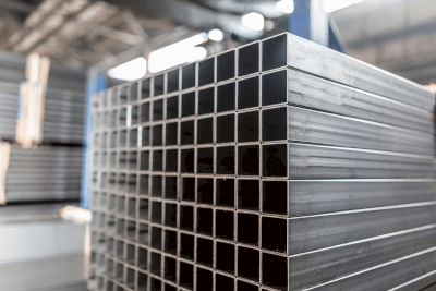
What Is a Metal Square Tube?

Metal Square TubesA metal square tube is a general term for structural materials made of stainless steel, steel, alloys, etc., created through extrusion mold.

The cross-section of a steel pipe is typically square, but it can be cut to any desired length and shape. Many ready-made products come in standardized sizes, materials, and lengths, making it relatively easy to purchase in large quantities.

A “flat square pipe” has a rectangular cut surface, while a commonly referred to “square pipe” has a square cross-section.

Uses of Metal Square Tubes

Depending on the material, hard superalloy and steel square pipes are used for iron fences and fittings. They are also employed for retrofitting balcony floors and structural pipes for material racks, taking advantage of their load-bearing capacity.

As a construction material, this structural material is often used in sunroom construction and exteriors. It is also utilized when setting up materials in factories and plants, balcony and emergency staircase railings, and fence enclosures on temporary decks.

Lightweight aluminum lumber is easily transportable, making it useful as a material for deck chairs and outdoor benches for poolside relaxation.

Principles of Metal Square Tubes

These materials are pressed and extruded in a die, resulting in relatively uniform quality and the ability to be mass-produced according to standards. Another advantage is their adaptability to various shapes through cutting and welding.

The product’s shape can be used as a rain gutter as is. The elegant brass color is an example of a remodeling application that leverages the material’s beauty.

In factories, they are used for machine structural materials, transportation carts, and construction of steel bridges for work. Commercially available joint pot parts that can be easily assembled are also used. When used as a conduit, it can be branched with an adjuster variation that connects to the joint.

In the field of music production, they are used as sound racks for various professional audio equipment, some of which weigh more than 220 pounds. The term “sound rack” commonly refers to a complete set of music equipment housed in a steel rack. The material not only offers functionality but its massive metallic texture adds to the realism of the sound production process.

カテゴリー
category_usa

Cup Grinding Wheel

What Is a Cup Grinding Wheel?

A cup grinding wheel is a type of grinding wheel that is shaped like a cup. Cup grinding wheels offer several advantages, including a larger contact area with the object being ground and reduced clogging compared to flat grinding wheels.

One distinctive feature of cup grinding wheels is their suitability for front grinding, a process that can be challenging with flat wheels. Front grinding involves using the bottom surface of a cup grinding wheel and is known for delivering excellent results in terms of surface roughness, flatness, and efficiency.

Uses of Cup Grinding Wheels

Cup grinding wheels find applications across a wide range of industries, including can manufacturing, sheet metal processing, and mold forming. They are often employed for tasks such as press punching, edge deburring, and rounding, depending on the size of the grinding wheel and its rotational speed during operation.

While a traditional flat grinding wheel is primarily used for surface grinding, cup grinding wheels excel at front grinding due to their cup-shaped design. This makes them ideal for achieving superior grinding outcomes in terms of precision and efficiency.

Principles of Cup Grinding Wheels

Cup grinding wheels are characterized by their cup-like shape, which includes both cylindrical straight cups and tapered cups with wider openings at the top. These wheels come in various heights and diameters to suit different applications.

Common materials for manufacturing cup grinding wheels include ceramics such as white alumina and light red alumina. The grain size of these ceramics can vary, allowing users to select the appropriate grain size for their specific grinding needs.

One of the key advantages of cup grinding wheels is their suitability for front grinding, a task that can be challenging with flat wheels. Front grinding is highly effective in achieving superior surface roughness, flatness, and overall grinding efficiency.

Cup grinding wheels are versatile and can be used in various applications. In addition to their common use for grinding metals and ceramics, some cup wheels are designed for grinding sensitive materials like glass by implementing measures to manage heat generation during the grinding process.

There is a diverse range of cup grinding wheels available, including options designed to reduce noise generation during grinding, making them suitable for a wide array of products and environments.

カテゴリー
category_usa

Rotary Clamp Cylinder

What Is a Rotary Clamp Cylinder?

A clamping cylinder is a commonly used machine tool in automated production lines, designed to secure (clamp) a workpiece in place for various processes, such as drilling, performed by a robotic arm or spot welder.

The clamping cylinder employs pneumatic or hydraulic pressure to move a component called the rod in a linear motion, either vertically or horizontally, effectively immobilizing the workpiece during the manufacturing process.

A rotary clamp cylinder is a variation of the clamping cylinder that incorporates a rotating mechanism into the rod.

Uses of Rotary Clamp Cylinders

Clamp cylinders are essential for securely holding workpieces in automated production lines.

Rotary clamp cylinders are specifically employed for clamping purposes during machining or welding operations. Their design is optimized for space efficiency, ensuring that the clamping point does not obstruct the flow of workpieces during loading and unloading before and after machining or welding processes.

The clamp arm, often referred to as a clamp lever, is capable of swiveling to secure the workpiece. When not in use, the clamp lever can be positioned in a way that does not interfere with the loading or unloading of workpieces in an automated production line. This compact design helps save space and streamline operations in automated manufacturing environments.

Principles of Rotary Clamp Cylinders

The rotary clamp cylinder’s rod is equipped with a swiveling mechanism, often driven by a cam mechanism utilizing a groove on the rod itself.

In scenarios where workpieces need to be clamped at two separate locations on the left and right sides of an automated production line, the direction of rotation for the clamp levers on each side can be reversed, reducing the time needed for rotational movement. Rotary clamp cylinders are well-suited for such applications.

These cylinders can be powered by compressed air for pneumatic operation or hydraulic pressure for applications requiring substantial clamping force. In cases where high clamping force is necessary, hydraulic systems are often preferred.

It is worth noting that while the rotary clamp cylinder’s rod swivels during operation, not all models are capable of simultaneous clamping and swiveling. Careful consideration is required when selecting and operating these cylinders.

There exists a trade-off relationship between allowable clamp lever length and clamping force, as well as between the allowable moment of inertia of the clamp lever and piston speed for each model. Several factors, including usage conditions, clamp lever shape, length, weight, and various specifications, impact the calculation of moment of inertia. Therefore, it is advisable to thoroughly review the specifications provided by the manufacturer before usage.

Additionally, some models support horizontal operation, while others do not. The choice of model and manufacturer should align with the overall equipment design of the automated production line.