カテゴリー
category_usa

Power IC

What Is a Power IC?

Power IC, a term for integrated circuits (ICs) containing power semiconductors, is used in high-power circuits. Power semiconductors include components like power transistors, power MOSFETs, and IGBTs. These are essential in controlling high currents exceeding 1A among various semiconductor materials.

Uses of Power ICs

Power ICs find extensive use in industrial applications, including:

The Power IC market is poised for growth, especially due to increasing demand for vehicle applications.

Principle of Power IC

Power ICs are crucial for voltage control in motor-driven applications and charging storage batteries. They are central in power supply management, used for AC/DC conversion, and boosting voltage in DC power supplies. These ICs typically leverage the rectifying action of semiconductor devices and the characteristics of capacitors.

Other Information on Power ICs

1. Semiconductors Controlled by Power ICs

Components integrated into Power ICs include:

Emerging materials like silicon carbide (SiC) and intelligent power modules (IPMs) are also gaining prominence in Power ICs.

2. Future Prospects of the Power IC Market

Power IC demand spans the information, telecommunications, consumer, industrial, and automotive sectors. The automotive sector, in particular, has seen significant growth with the advent of electric vehicles. The consumer and industrial sectors have also shown recovery post-pandemic, with expectations of further growth.

3. SiC as a Power IC Material

SiC, a compound of silicon and carbon, is a promising next-generation power semiconductor material. It offers higher dielectric breakdown strength and a wider band gap than silicon, allowing for ICs with lower power consumption and higher breakdown voltage. Other materials like gallium nitride (GaN) and Ga2O3 are also being considered for future power semiconductor applications.

カテゴリー
category_usa

Panel Rack

What Is a Panel Rack?

Panel racks are versatile storage fixtures commonly used for organizing tools and parts. They allow items to be hung from hooks or horizontal stiles on a vertical surface. These racks can include shelves attached to a horizontal surface using holding fixtures, or hooks for hanging plastic boxes of different colors for part storage and management.

The vertical surfaces of panel racks may consist of perforated panels with regularly patterned holes, or horizontal stiles set across the frontage, supported by columns.

One key advantage of panel racks is their ability to keep the entire vertical storage area visible. This visibility aids in visualizing and managing stored items, improving work efficiency by quickly identifying the location of parts and tools.

Applications of Panel Racks

Panel racks are widely used in various manufacturing, packaging, and processing environments for storing parts and tools. They can be effectively placed in different locations, such as clamped behind a tabletop, mounted on casters for floor placement, attached to the side of a shelf, or installed on an underutilized wall surface.

Principle of Panel Rack

Panel racks typically consist of a support structure with perforated panels or horizontal cleats between posts. They can be configured in multiple ways: clamped to a workbench top, freestanding with legs and casters, fixed to a wall surface, or mounted on an unused side of a medium-volume rack.

Regardless of the type, all panel racks offer instantaneous visibility of stored items, enabling efficient and visualized management. They accommodate various storage parts and tools, with options for different types of hooks (suitable for screwdrivers, pliers, etc.) that easily attach to the perforated panel. Side panels can be used to hang color-coded plastic boxes for part storage. Additional features, like holding metal fittings and a hanger bar, can be added to hold shelf boards or hang tools like electric screwdrivers and air tools for efficient work organization.

カテゴリー
category_usa

Double-Pitch Chain

What Is a Double-Pitch Chain?

A double-pitch chain is a variation of a standard roller chain, designed with the distance between roller tips being twice as long as that of a regular roller chain.

This design reduces the number of parts, thereby lowering costs. Specifically, the number of teeth on sprockets and the number of link plates and pins are halved compared to normal chains. This results in lower assembly costs and simpler equipment design.

Applications of Double-Pitch Chain

Double-pitch chains are frequently used in conveyor belt roller movements. They are generally not suitable for high-speed or precision applications, as the extended pitch can cause increased vibration when the sprocket teeth engage with the chain.

Depending on the material, double-pitch chains can be used underwater or in environments with corrosive gases like acids and alkalis. In such conditions, stainless steel chains, known for their high corrosion resistance, are preferred.

Principle of Double-Pitch Chain

A sprocket, similar to a gear or chain wheel as seen on bicycles, engages with the chain to transfer rotational force from a pedal or motor. By using chains and sprockets of consistent sizes, multiple sprockets can be driven at the same rotational speed with a single power source.

The rotation speed is adjusted by altering the size and number of teeth on the sprockets, tailored to the specific equipment requirements.

Careful consideration is needed for the number of links in the chain and the number of teeth on the sprockets. Ideally, these should be an odd and even number combination to prevent the same teeth from continuously engaging with the same chain links, which could lead to accelerated wear and failure.

カテゴリー
category_usa

Delivery Hose

What Is a Delivery Hose?
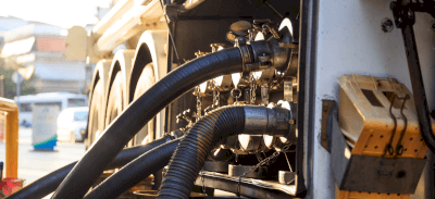
Delivery Hoses

A delivery hose is a rubber or synthetic resin hose reinforced with materials such as steel wire or polyester thread.

It is used in plumbing work because it is bendable, lightweight, and easy to cut and install. There is a wide range of inner diameters from 20 mm to 300 mm and wall thicknesses from 2 mm to 16 mm. The hose material, reinforcement material, and dimensions are selected based on the flow rate, flow velocity, allowable pressure, ambient environment, installation conditions, and bending radius, among other factors.

Uses of Delivery Hoses

1. Fuel Delivery

Delivery hoses are crucial tools used for fuel delivery. They are utilized in various settings, such as gas stations, aviation fuel delivery, and industrial fuel delivery, to transport fuel efficiently and safely.

2. Transportation of Liquid Chemicals

Delivery hoses are employed to transport a variety of liquid chemicals, including chemicals and liquid raw materials. Special materials and coatings provide chemical resistance and allow for the safe transport of these substances without compromising their properties.

3. Food Industry

In the food industry, delivery hoses transport liquid and powder ingredients and products. They ensure efficient supply while maintaining the quality of food.

4. Supply of Construction Materials

Delivery hoses are also utilized to supply building materials such as concrete, cement, and sand at construction sites. They are effective for supplying materials at high elevations or when access to tight spaces is challenging.

5. Agriculture

In agriculture, delivery hoses spray and deliver liquids such as pesticides and fertilizers. They ensure even distribution while maintaining crop health.

6. Industrial Water Supply

Delivery hoses are used to supply cooling and processing water in industrial facilities. Flexible hoses facilitate the delivery of water to specific locations.

7. Cleaning Operations

Delivery hoses are also used in the cleaning industry for high-pressure washing and spraying detergents. They support efficient cleaning operations and improve environmental and hygienic conditions.

Principles of Delivery Hoses

1. Flexibility and Durability

Delivery hoses are made of high-quality synthetic rubber, plastic, or a combination of the two. This flexibility and durability allow the hoses to bend, stretch, and contract while still ensuring the reliable transport of materials.

2. Internal Structure

The interior of delivery hoses is designed to allow an unobstructed flow of liquids and gases. Smooth inner walls and appropriate diameters minimize fluid resistance and promote efficient flow.

3. Safety and Efficiency

Delivery hoses provide both safety and efficiency in the transportation of materials. Accurate flow control and proper pressure management ensure efficient movement and safe use of materials.

Types of Delivery Hoses

1. Hoses for Transporting Chemical Substances

Hoses are utilized in the chemical and manufacturing industries to transport various chemicals. These hoses feature high chemical resistance and are suitable for moving various corrosive and hazardous materials.

2. Food Grade Hoses

Food-grade hoses are employed in the food industry to transport materials such as liquids and powders. They must meet safety standards and be safe from contact with food products.

3. Fuel Hose

Fuel hoses are used for supplying fuel and refueling vehicles. They must be resistant to fuel and ensure a tight, leak-proof connection.

4. Air Compression Hose

This hose is utilized at industrial sites and for automobile maintenance, supplying air from air compressors and powering tools. Pressure resistance and abrasion resistance are crucial.

5. Water Supply Hose

Used in homes and commercial facilities, water hoses are employed for water supply and irrigation. Water resistance and durability are required, making them suitable for indoor and outdoor use.

6. Medical Hoses

Hoses used in medical equipment and settings are employed to supply fluids and gases. They require cleanliness and durability and are designed for various medical environments.

7. Vibration Absorbing Hoses

These hoses have a special construction that absorbs and does not transmit vibrations from machinery and equipment. They are used in certain machines and systems to reduce damage and noise caused by vibration.

Other Information on Delivery Hoses

1. Selection of Appropriate Material

Delivery hoses are selected based on the characteristics of the materials to be conveyed. Factors such as chemical resistance, temperature resistance, and pressure resistance are considered to select the most suitable hose for the material’s nature.

2. Importance of Connections

Delivery hoses must be securely connected to the pumps, valves, nozzles, etc., being used. A firm connection prevents leakage or spillage of the substance and ensures safe transport.

3. Consideration of Operating Environment

Delivery hoses are selected based on the environment in which they will be used. To meet different conditions indoors, outdoors, and in various industries, characteristics such as weather resistance and chemical resistance are considered.

カテゴリー
category_usa

Display Extender

What Is a Display Extender?

A display extender is a device that extends video signal reach beyond the limitations of a standard display cable. It enables a display to receive signals from a distance, essential for setups where the display and signal source are far apart.

The device comprises a transmitter near the PC, a receiver for video signals, and a cable connecting the two. Display extenders can handle both analog and digital signals, with digital systems offering higher image quality.

Usage of Display Extenders

Display extenders are widely used in various settings. In hospitals, they allow for the display of images on remote screens, especially useful where space constraints prevent the installation of large video output devices. This leads to a simple setup comprising just the wiring and display.

In industrial settings, they connect server rooms to monitoring rooms, especially when the distance is substantial. LAN cables are often used for their flexibility and bending capacity compared to standard display cables.

Principle of Display Extender

A Display extender operates as a signal converter. Using a LAN cable, it converts HDMI or VGA standard electrical signals to Ethernet standard at the transmitter. At the receiver, the conversion is reversed to output video signals. When an optical cable is used, conversions between electrical and optical signals are facilitated using devices like photodiodes. This process is akin to media converters.

Other Information on Display Extenders

Cables Used for Display Extenders

Aside from LAN cables, optical cables are also employed for display extenders, particularly useful for long-distance connections. Traditional VGA cables have largely become obsolete. HDMI cables are now common, with LAN cables effective up to 100 meters. Beyond this, a hub is required.

LAN cables are cost-effective, easy to fabricate, and can be custom-lengthened with basic tools. Optical cables can extend several kilometers but are impact-sensitive and need specific devices for connection. For short distances, HDMI direct connection is preferred, LAN cables for up to 100 meters, and optical cables for longer distances. Additionally, optical cables are beneficial in environments with electromagnetic interference, as they are not affected by such disturbances.

カテゴリー
category_usa

Thrust Needle Roller Bearing

What Is a Thrust Needle Roller Bearing?

Thrust Needle Bearings

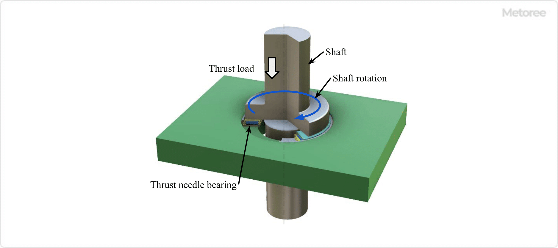
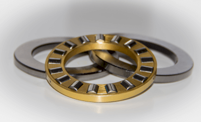
A thrust needle roller bearing consists of needle rollers and retainers, designed to support axial thrust loads (parallel to the shaft’s center).

Figure 1. Thrust needle bearing and thrust load

Figure 1: Thrust Needle Roller Bearing and Thrust Load

Thrust needle roller bearings are the most compact among all thrust bearings. They allow for high-speed rotation without generating significant friction.

A thrust needle roller bearing is a thrust bearing with needle rollers as rolling elements.

Uses of Thrust Needle Roller Bearings

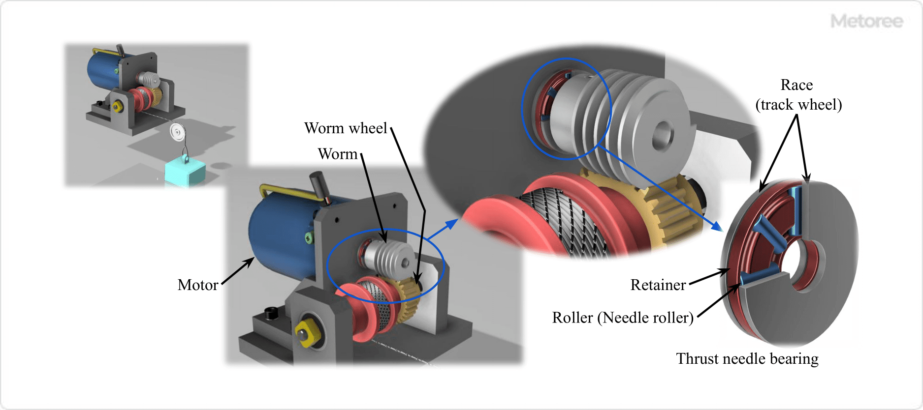
Figure 2. Example of thrust needle roller bearing use

Figure 2: Application of Thrust Needle Roller Bearing

Thrust needle roller bearings are rigid, compact, and capable of handling large loads and high speeds, making them suitable for various applications.

In automobiles, they are used in areas supporting high axial loads, such as engines and differential gears, and as bearings in automatic transmissions. Other applications include machine tools, robots, aircraft, and industrial machinery.

Figure 1 illustrates their use in a winch with a worm gear, where the worm attached to the motor output shaft exerts a thrust load towards the center of the worm shaft. A thrust needle roller bearing is incorporated to prevent the load from affecting the motor output shaft.

Principle of Thrust Needle Roller Bearings

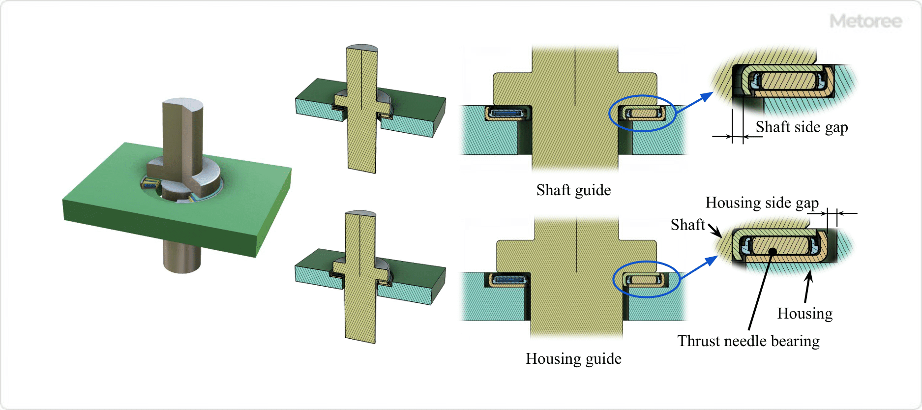
Figure 3. Shaft guide and housing guide

Figure 3: Shaft Guide and Housing Guide

Thrust needle roller bearings feature needle rollers arranged in a circumferential pattern, with retainers maintaining the spacing between rollers and allowing each to rotate independently. This design supports high loads through linear contact, with a small contact area that results in low friction, even at high rotational speeds.

Thrust needle roller bearings can be mounted in two ways:

  • Shaft Guided (Bore Guided): Large clearance between the shaft and bearing inner side, with a small clearance between the housing and bearing outer side.
  • Housing Guided (Od Guided): Large clearance between the housing and bearing outer side, with a small clearance between the shaft and bearing inner side.

They are primarily used with shaft guideways and are recommended for high-speed rotation applications.

Types of Thrust Needle Roller Bearings

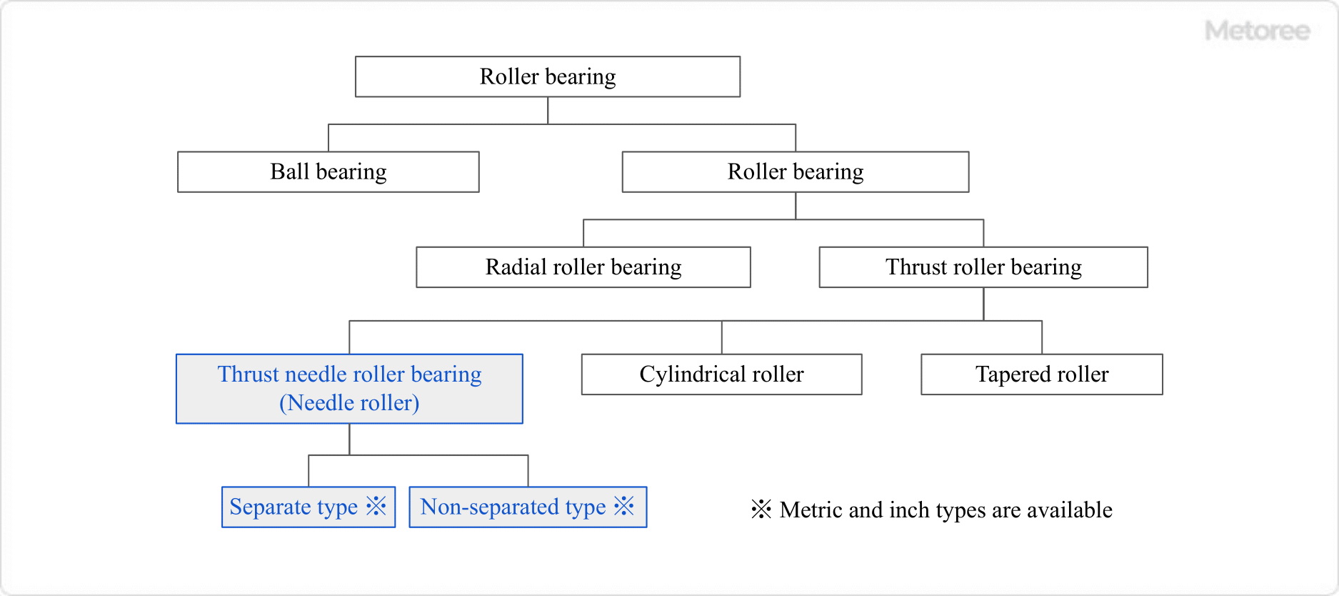
Figure 4. Bearing type system

Figure 4: Bearing Type System

Roller bearings are broadly classified into ball bearings and roller bearings, which are further categorized into radial and thrust roller bearings, respectively. Thrust needle roller bearings fall under the thrust roller bearing category.

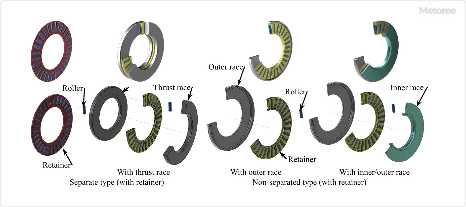
Depending on the roller shape, there are needle rollers, cylindrical rollers, and tapered rollers. Thrust needle roller bearings come in separated and non-separated types, distinguished by whether the needle roller and retainer can be detached from the thrust race or are integral and non-detachable.

Figure 5. Types of thrust needle bearing

Figure 5: Types of Thrust Needle Roller Bearings

Separate types can be used either with the retainer and needle roller between the thrust races or without a thrust race. For bearings without a thrust race, the needle roller contact surfaces must be finely ground and hardened. Thrust races come in two types: shaft guideway and housing guideway.

カテゴリー
category_usa

Jaw Flex Coupling

What Is a Jaw Flex Coupling?

Jaw Flex Couplings

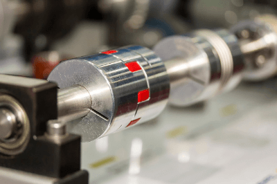
Jaw flex couplings belong to the category of flex couplings.

A coupling, or shaft coupling, serves as a mechanical component that links a drive shaft with a driven shaft to transmit power. Flex couplings are designed to absorb misalignments between the drive and driven shafts, thereby mitigating misalignment effects.

In contrast, rigid couplings offer zero backlash and efficient power transmission. Jaw flex couplings excel in vibration and shock absorption due to rotational movements and are straightforward to install and remove.

Uses of Jaw Flex Couplings

Jaw flex couplings are primarily utilized as shaft couplings in machinery prone to significant vibration and shock. Their outstanding vibration and misalignment absorption capabilities make them particularly suited for shaft couplings in induction motors and other applications demanding high-speed rotation and high torque.

Easy to maintain, jaw flex couplings with sleeves allow for disassembly and assembly without the need to move the drive and driven shafts by merely removing the sleeve.

They are also employed as shaft couplings in pumps, compressors, blowers, machine tools, packaging machines, robots, and more.

Principle of Jaw Flex Couplings

Couplings fulfill four crucial functions:

  • Power transmission from the drive shaft to the driven shaft.
  • Absorption of mounting errors between the drive and driven shafts.
  • Vibration absorption of the drive shaft, preventing its propagation to adjacent equipment.
  • Heat transmission from the drive shaft to the driven shaft.

Jaw flex couplings are notably efficient in the second and third functions mentioned. They incorporate a sleeve (or spider, or in-shear spider) between the drive and driven shafts to allow for a degree of misalignment (eccentricity, angular misalignment, axial displacement, etc.) and use their flexibility to absorb vibration and shock, ensuring stable rotation. This tolerance to misalignment also reduces the need for high machining precision, thereby lowering production costs and simplifying machine assembly and adjustment.

When utilized in motor couplings, jaw flex couplings partially shield the motors from operational vibrations.

Types of Jaw Flex Couplings

Jaw flex couplings vary in construction, sleeve shape, and material.

1. Classification by Construction

The fundamental structure of a jaw flex coupling includes a hub on the drive shaft, a hub on the driven shaft, and a cushioning material inserted between the hubs to connect the shafts.

The cushioning material comes in three shapes: sleeve type, spider type, and in-shear spider type. The in-shear spider type includes an external retainer for protection.

2. Classification by Material

The materials commonly used in jaw flex couplings are detailed below.

Hub materials are selected based on the operating environment, including considerations for corrosive conditions. Sleeves and spiders, as cushioning materials, vary in characteristics depending on the material and are chosen according to the operating temperature range and shock compatibility.

Nitrile rubber offers excellent impact resistance but is less chemically resistant than urethane, though it has a slightly broader operating temperature range. Copper alloy is preferred for high-torque applications, particularly at low rotational speeds.

カテゴリー
category_usa

Joint Boot

What Is a Joint Boot?

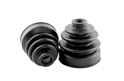
Joint BootsA joint boot is a protective rubber device used in automotive joints like constant velocity joints and ball joints. They seal in lubricating grease and prevent foreign substances like dust and water from entering. There are two main types of joint boots: one for parts involving centrifugal force, expansion, and contraction, and another for tilting movements.

Uses of Joint Boots

Joint boots are essential in various automotive parts, ensuring the smooth operation and longevity of components. They are used in:

  • Driving Parts: Constant velocity joints in drive shafts.
  • Suspension Equipment: Ball joints in suspension arms and knuckles.
  • Steering Device: Components in rack-and-pinion and ball-and-nut steering systems.

Their application in the steering and suspension systems, as well as in drive parts, highlights their importance in vehicle safety and performance.

Principle of Joint Boots

Joint boots operate under challenging conditions, enduring constant bending, turning, and exposure to harsh elements. Made of rubber, they are prone to breakage and deterioration over time. This is especially critical for drive shaft boots, which rotate at high speeds. A broken or cracked boot can lead to grease leakage, causing noise, vibration, and potential safety hazards.

Split-type boots, designed for easier replacement, have the convenience of a single cut sealed with adhesive. However, they may be less durable than non-split types and require careful maintenance to prevent grease leakage.

カテゴリー
category_usa

Zip Chain Actuator

What Is a Zip Chain Actuator?

A zip chain actuator is an innovative actuator that operates using a unique linear motion mechanism called a zip chain. This mechanism involves two chain-like structures pressed against each other, engaging like a zipper on clothing, which allows for linear motion perpendicular to the pressing force.

Applications of Zip Chain Actuators

Zip chain actuators are advantageous for their compact design, high-speed operation (up to 1000 mm/sec), and the ability to stop at any point along their stroke. They are ideal in situations requiring large strokes within limited spaces, such as in lifters or dollies that need rapid, precise movement and variable stopping positions. These actuators can be installed in any direction, accommodating both lifting and lowering actions.

Principle of Zip Chain Actuator

The zip chain actuator comprises two interlocking chains, a tip bracket, a chain housing, and a gear and shaft setup for power transmission. The chains interlock at the tip through metal fittings, and as they are fed out of the housing, they form a single, sturdy chain structure. This design allows for compact storage relative to the actuator’s stroke length.

The drive transmission unit, featuring a gear fixed to a rotating shaft, offers superior positioning accuracy compared to pneumatic cylinders. With motor-driven operation, the reduction ratio can be externally adjusted, facilitating complex feedback control and high-speed linear motion.

カテゴリー
category_usa

Sheet Pile Shoring

What Is Sheet Pile Shoring?

Sheet Pile Shoring Sheet pile shoring is a construction technique used for supporting earth in excavation and burial projects. This method involves creating a shallow trench and placing plates on either side to retain the earth. The setup is supported by cut beams, which are adjustable to change the spacing between the plates. Known for its simplicity, sheet pile shoring requires few parts and can be easily assembled and disassembled by a small team.

Uses of Sheet Pile Shoring

Sheet pile shoring is commonly employed at excavation sites, particularly for the underground installation of utilities like water, sewage, and electrical pipes. It provides essential support in trenching operations, especially when trenches are as deep as a person’s height, to ensure the safe and stable installation of pipes. This technique is adaptable for both heavy and light earth pressure situations, depending on the depth and stability requirements of the excavation.

Principle of Sheet Pile Shoring

Sheet pile shoring is a form of earth retaining used to prevent ground collapse during excavation and to manage water flow. The choice between heavy and light earth pressure plates depends on the trench depth. For deeper trenches prone to collapse, heavy earth pressure plates supported by struts are used, whereas shallower trenches may require only the plates for support.

The cut beams, typically pipe-shaped, are inserted horizontally between plates to maintain stability. Additionally, other ground-supporting methods like gravity or leaning types can involve concrete retaining walls for earth retention.