カテゴリー
category_usa

Double-acting Cylinder

What Is a Double-acting Cylinder?

A Double-acting Cylinder is a type of cylinder that is a positioning device. It has a rod inside a cylindrical tube and operates using compressed air. The cylinder can position only two main lengths: extension and contraction.

A single-acting cylinder is one that uses compressed air only for extension and a spring-operated cylinder with no compressed air for contraction.

Uses of Double-Acting Cylinder

There are various types of cylinders. They include air cylinders, robotic cylinders, and single-axis robots. Air Cylinder powered by compressed air is a generic term for Double-acting Cylinder and Single-acting Cylinder.

RoboCylinders combine a motor and a ball screw to control the amount of stroke. Single-axis robots are used to transport heavier objects than RoboCylinders.

Double-acting cylinders use compressed air, so they are simple in construction, inexpensive, and lightweight.

Principle of Double-acting Cylinder

Double-acting cylinders have a cylindrical tube covered at both ends with head covers and rod covers, which are tightened with four tie rods.

When cylinders with smaller diameters are used, the covers are screwed or caulked together without the use of tie rods. Inside the tube is a piston that fits with the tube, and the rod attached to the piston passes through the rod cover to transmit force to the outside. The head cover and rod cover are provided with ports for supplying and discharging air to and from the cylinder, and air is alternately supplied to the front and back of the piston for reciprocating motion.

They vary depending on where they are mounted: foot type with an L-shaped bracket, rod flange type with a flange on the rod side of the cylinder, head flange type with a flange on the head side of the cylinder (the side opposite the rod), and single or double clevis mounting with a clevis.

カテゴリー
category_usa

Bag Stitch Machine

What Is a Bag Stitch Machine?

Bag Stitch Machines

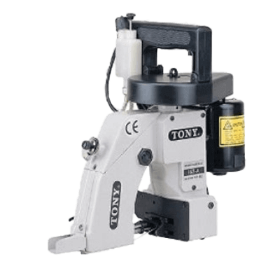
A Bag Stitch Machine is a specialized sewing machine for industrial use that can sew a bag with a single operation.

There are also hand-type sewing machines mainly used in the field, stationary machines that can measure the load while sewing, and convenient machines that can attach tags and labels on the workbench. There are one-thread and two-thread setting types, with the difference being in strength created by the seam allowance of the back thread.

Uses of Bag Stitch Machines

The main applications are feed and grain bags in the agricultural and livestock sector; they are used for sewing the mouths of jute bags weighing 30 kg to 50 kg and polyester material after filling.

Familiar examples include the well-known paper-made 30 kg rice bags. It is also used for coffee bean bags made of jute.

Other applications include sewing artificial lawns, free stitching of canvas, and temporary repair of tents, taking advantage of the freedom of mobility.

Principle of Bag Stitch Machine

The characteristics of sewing machines are generally divided into large hand sewing machine types and tabletop sewing machine types. Depending on the sewing capacity and application, there is a single-thread type that can also be used for back stitching with one front thread, and a double-thread type that can create a double chain for each of the front and back threads.

The hand-sewing machine type is popular for its portable convenience. When you want to inspect the contents of a loaded bag, you can close the opening again without unloading the bag. You can handle the equipment at any angle you want without the need to move the cargo.

Both single-thread and double-thread types are available. There are also high-end models on the market that are capable of sewing thick jute bags of coffee beans.

Bag Stitch Machines with a loading platform or tabletop are suitable for weighing and inspecting loads. They are attractive for sewing labels and tags at the same time. The stability of the machine makes it suitable for sewing products that require a beautiful seam allowance and for large-volume sewing work that requires accuracy.

カテゴリー
category_usa

Insulating Base

What Is an Insulating Base?

An Insulating Base is a table base used to ensure the insulation of electrical equipment.

The table is not a table, but rather a part that is attached under the legs of the table. If the floor is made of metal such as grating, electricity will flow through the floor, affecting other equipment and, in the worst case, leading not only to equipment damage but also to fire or electric shock.

The use of an Insulating Base is to avoid such accidents.

Uses of Insulating Base

Insulating Bases are used to support bus bars, which need to be insulated, and to mount equipment such as control panels, distribution boards, and rectifier panels.

Insulating Bases are fixed to the wall, but when installed on the ground, it is safer to raise them slightly off the ground by attaching an Insulating Base stand to the bottom of the Insulating Base.

On the other hand, the Insulating Base cannot be used in an exposed position outdoors, where it may get wet in the rain, due to its nature.

Principle of Insulating Base

In the industrial world, accidents unfortunately occur despite efforts to eliminate them, and electric shock is one of the most likely to occur.

Of course, there are cases in which accidents are caused by the carelessness of the user, but they are also rare due to design errors or inadequate safety equipment. Electrical accidents are not limited to electric shock, but can also cause fires, short circuits, and other accidents that result in high voltages being applied to other equipment, which can cause damage.

Therefore, it is necessary to pay close attention to safety when using electricity. From this accident prevention point of view as well, the installation of insulating support base stands is an important device for ensuring safety.

An Insulating Base is made of polypropylene or other highly insulating material, which provides a high level of insulation. They can be installed simply by tightening with screws, so they are easy to use and can be used simply by drilling screw holes. Since the insulating support bases can be connected together, the height can be adjusted.

カテゴリー
category_usa

Insulation Cover

What Is an Insulation Cover?

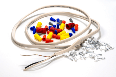
Insulation CoversInsulation covers are safety protective covers used to insulate and protect the charging section of fixtures, the wiring section, and the exposed charging section of high-voltage overhead distribution line clamps.

There are three types of covers: a one-touch push type that is pushed into an outlet, a type that is fitted by passing an electric wire through it, and a heat-shrink type that is covered over the charging section of a fixture and shrunk by a hair dryer or the like. Types that are used by cutting them according to the length of the terminal block.

Since they are safe and protective goods, it is important to select the appropriate cover for the applicable part, considering the material, terminal block standards, outer diameter of the applicable wire, operating voltage, insulation resistance, and other factors.

Uses of Insulation Covers

Insulation Covers are widely used in electrical work, machine repair, maintenance of construction equipment and machinery, communication equipment, home appliances, automobiles, motorcycles, etc.

Examples of use are as follows:

  • Installation of solar panels
  • Wiring with bare crimp terminals
  • Wiring of driving chargers
  • Cable maintenance
  • Wiring work in a panel
  • Protection of connections for small basic switches
  • Wiring of home appliances, electronic circuits, machines, etc.
  • Preventing grounding electric shock accidents by attaching to armbar, HCF, etc.
  • Protection of low-voltage switchgear
  • Grip protection for extended wires

Principle of Insulation Cover

Insulation Covers made of ABS resin, polyolefin, etc. are used for medium-voltage power supply connections and conductor connections of less than 300 V, such as charging sections, joints, bolt sections, support connections, etc. of one-touch push type for outlets and simple structures.

Heat-shrinkable tubing is also available, in which the charging and wiring parts of the device are covered so that they are not exposed, and then heat-shrinked with a gas torch, industrial dryer, etc.

The applicable current for the heat-shrinkable tube specification is 100A, and the voltage is 600V. The insulating cover that protects the tip of the power cable with the terminal from short circuits is made of 0.4 mm thick polyurethane with a double structure and a solid adhesive treatment.  Not too hard, not too soft, it has an exquisite hardness, so it feels good to use, and is transparent so you can check the polarity and phase of the cable.

Terminal insulating covers such as battery terminal insulating rubber covers are made of flexible PVC material. The red and black colors help prevent accidental shorts and improve the appearance of your wiring.

Widely used in communication equipment, home appliances, automobiles, motorcycles, etc. Insulating covers for high-voltage distribution lines such as steel towers for transmission lines, dead-end clamps for high-voltage overhead distribution lines, sleeve and connector connection points, branches for low-voltage overhead distribution lines, and wire connections for secondary terminals of pole transformers.

Polyethylene, which has high insulation, flexibility, durability, and weather resistance, is mainly used.

Covers designed with the shape and structure appropriate for each usage area can be used to improve work efficiency.

カテゴリー
category_usa

Hexagon-Slotted Nut

What Is a Hexagon-Slotted Nut?

Hexagon Slotted Nuts

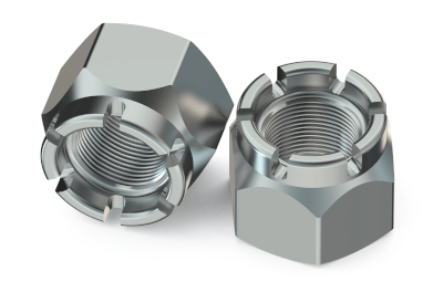
Hexagon-slotted and castle nuts are nuts with grooves cut into one end on all six sides. These grooves allow for the insertion of a split pin into a drilled hole in both the thread and the nut groove to prevent loosening.

They are sometimes referred to as “castle nuts” because their shape, including the grooves, resembles that of an old Western-style castle. Castle nut features a small surface area around the six grooved sides, facilitating a tight and compact wrap of the split pin around the nut.

Uses of Hexagon-Slotted Nuts

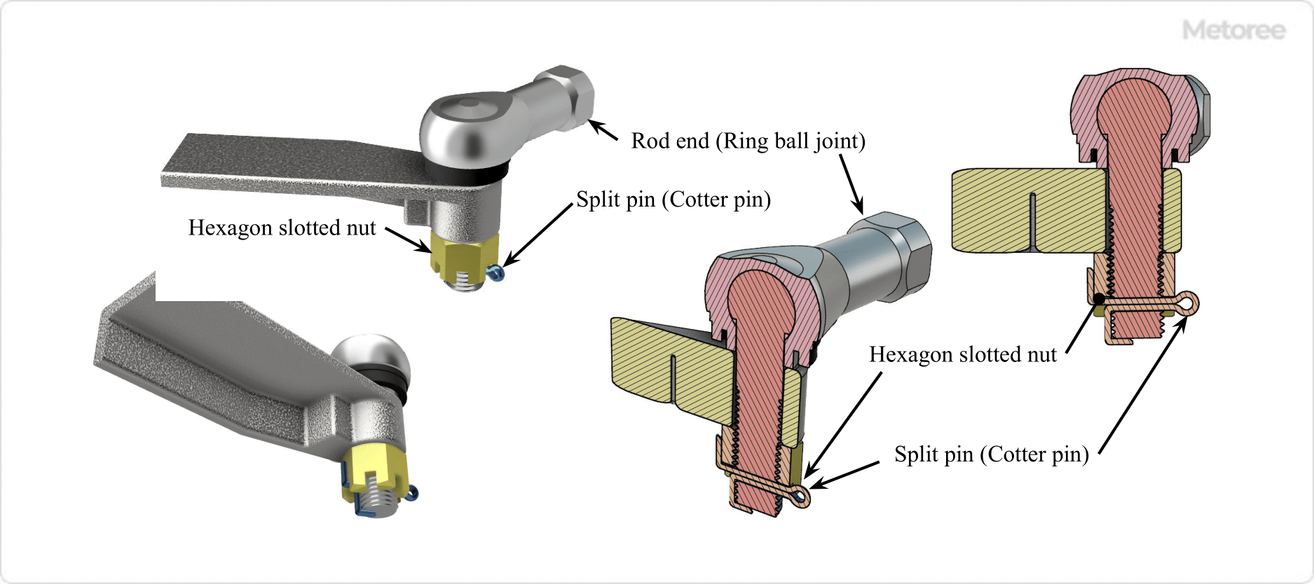
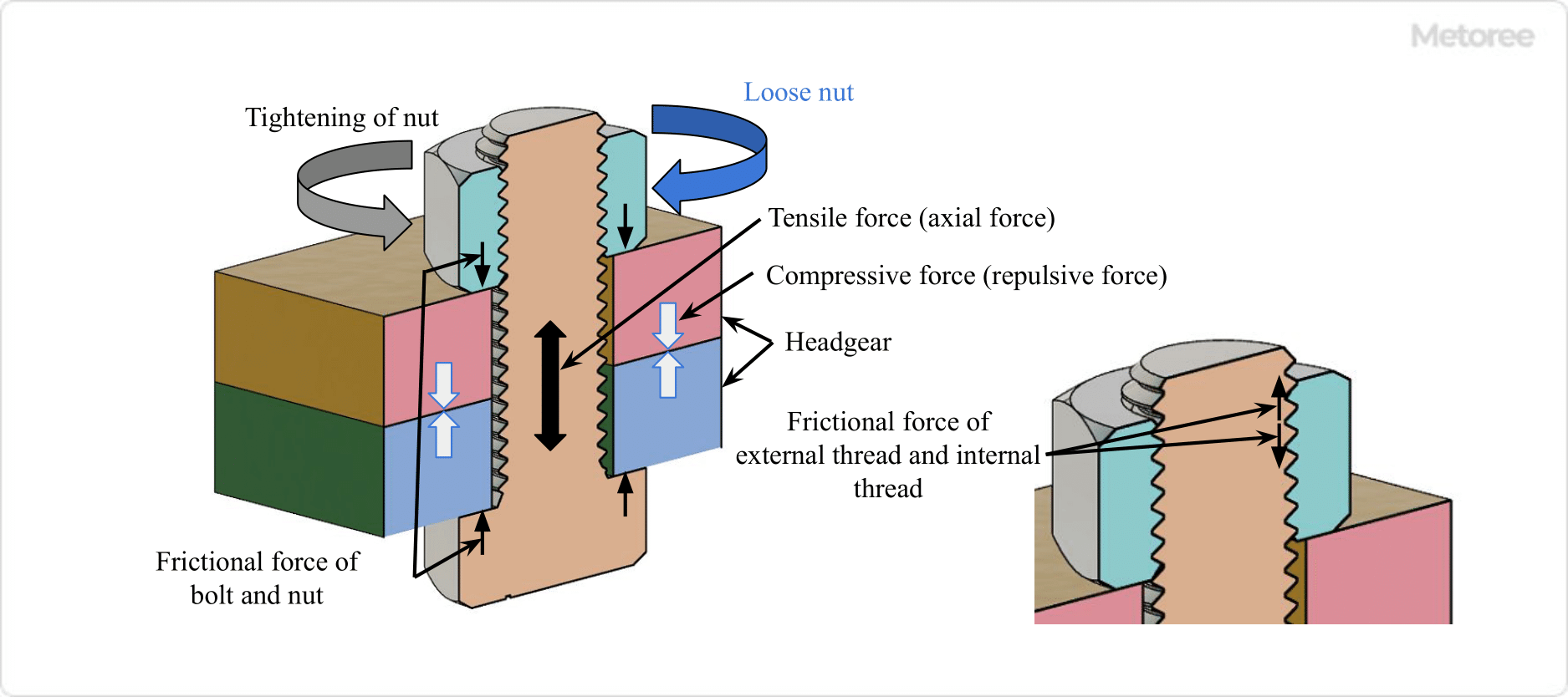
Figure 1. Example of grooved hexagon nut use

Figure 1: Application of Hexagon Slotted Nuts

Hexagon-slotted nuts are used to prevent loosening and nut dropout by inserting a split pin or similar device into the nut groove and threaded hole. Although various nuts are now widely available, hexagon-slotted nuts were frequently used for their reliable prevention of loosening.

However, because their installation requires drilling on the thread side, they are costly and can damage the thread. Nowadays, their use is limited to situations such as high-temperature environments or when the nut mustn’t fall off, even if loosened.

Hexagon-slotted nuts can be reused during disassembly and reassembly, but the split pin should not be reused; it must be replaced with a new one.

Principle of Hexagon-slotted Nuts

Figure 2. Principle of tightening and loosening screws

Figure 2: Principle of Screw Tightening and Loosening

The principle of screw tightening and loosening involves applying a compressive force to the fastened object and a tensile force to the bolt shaft, which is repelled by the object. This tensile force generates a frictional force between the bolt/nut’s seating surface and the fastened object, securing the screw in place.

In this state, three frictional forces work together:

  • The frictional force between the male and female threads
  • The frictional force between the fastened object
  • The frictional force between the bolt/nut seat and the fastened object

Screw loosening occurs when these frictional forces are reduced due to various factors, such as distortion or indentation of the seating surface, vibration-reducing axial force, or lubrication reducing friction between threads.

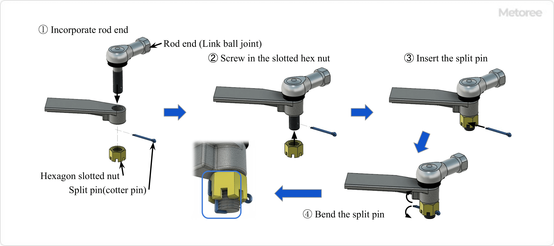
Figure 3. Installation of hexagon slotted nut and split pin

Figure 3: Installation of Hexagon Slotted Nut and Split Pin

The hexagon-slotted nut compensates for the reduction in initial axial force but does not prevent slippage of the seating surface or loosening due to the nut’s return rotation. Installation involves inserting a split pin into the bolt groove and threaded hole, bending the split pin tips into the groove along the nut side and the threaded side and end, ensuring the nut stays in place without loosening.

Types of Hexagon Slotted Nuts

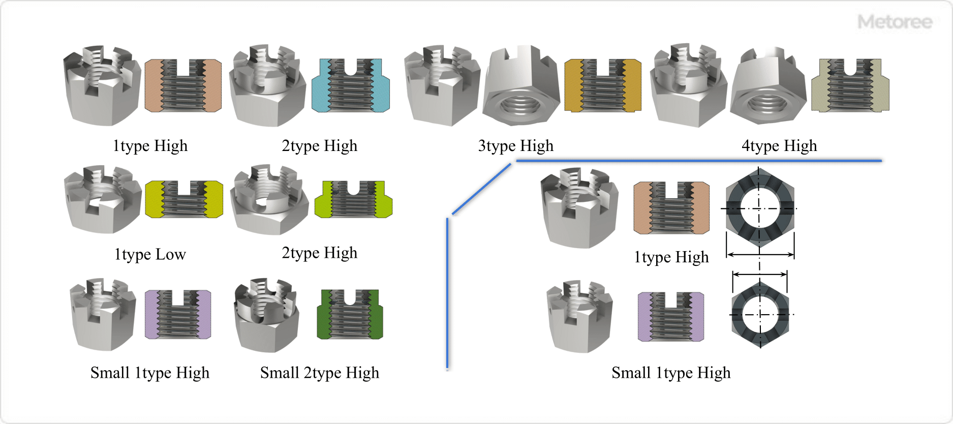
Figure 4. Types of hexagon slotted nuts

Figure 4: Types of Hexagon Slotted Nuts

The types of hexagon-slotted nuts are generally specified in various standards. Figure 4 illustrates each type and shape.

1. Type 1 High/Low

The hexagonal part has an infeed groove, and the nut height is high, suitable for small nominal diameters. This type is chosen when there are restrictions on nut height.

2. Type 2 High Type and Low Type

The high type features a groove from the hexagonal portion to the upper part, intended for large nominal diameters..

3. Type 3 and 4

Type 3 has a Class 1 seat, and Type 4 has a Class 2 seat, differentiating them by their seating surface specifications.

Other Information on Hexagon Slotted Nuts

1. Standards for Hexagon Slotted Nuts

  • ANSI/ASME B18.2.2 nuts for general applications: machine screw nuts, hex, square, hex flange, and coupling nuts (inch series)

2. Material of Hexagon Slotted Nuts

Hexagon-slotted nut materials are specified according to various standards. Some types and nominal diameters are to be determined by agreement between the delivery parties.

カテゴリー
category_usa

Wedge Pulley

What Is a Wedge Pulley?

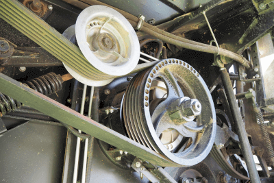
Wedge PulleysPulleys are pulley-shaped parts used in various machines and equipment, including automobiles. Normally, a belt is used to transmit power from a power source, such as a machine, and pulleys are used in combination with the belt.

A wedge pulley is used in combination with wedge belts, which are narrow V-belts.

Wedge belts create more frictional force than other types of belts of the same width. As a result, they provide greater transmission capacity, enabling high-speed and high-power transmission.

Uses of Wedge Pulleys

When using a belt to transmit power, it is necessary to select a pulley that matches the belt specifications. Wedge pulleys are used in combination with wedge belts.

The use of wedge belts in combination with wedge pulleys can save space and energy in the transmission system. Furthermore, wedge belts have a longer service life than normal belts and have been widely used in recent years. For example, wedge belts are used in various fields such as large pumps, compressors, forging presses, casting machines, paper manufacturing machines, crushers, hammer mill generators, band sawing machines, large machine tools, vibrating rollers, grinders, and freezers.

Principles of Wedge Pulleys

Wedge pulleys are used in combination with wedge belts to transmit power from a power source.

Wedge belts, being wedge-shaped, create a stronger frictional force than other common belt types of the same width. Therefore, when wedge belts are used with wedge pulleys, the transmission capacity is greater than when flat or V-belts are used with standard pulleys, allowing for high-speed, high-power transmission. As a result, the space required for the transmission equipment can be reduced compared to the space required for standard belts, thus realizing size reduction of the equipment.

Also, the use of wedge pulleys and wedge belts allows for efficient power transmission, which also saves energy.

In addition, the efficient operation also extends the life of the belt. Thus, the use of wedge pulleys in combination with wedge belts offers various advantages over the use of conventional pulleys and flat belts or V-belts.

カテゴリー
category_usa

SiC Diode

What Is a SiC Diode?

SiC diodes are semiconductor devices made from a compound of silicon (Si) and carbon (C).

SiC has about 10 times the dielectric breakdown strength and 3 times the band gap of silicon (Si), enabling the creation of smaller yet higher breakdown voltage circuit elements. SiC diodes, a prominent type of SiC power semiconductors, are used in discrete products or integrated into modules for applications in inverters, converters, IGBTs, and other devices.

The Schottky barrier diode, a type of SiC diode, is notable for its compact design and high-efficiency switching capabilities with low forward voltage. However, growing SiC wafers is more challenging than Si wafers, and processing SiC for semiconductor devices is also more complex. Thus, SiC diodes are not expected to entirely replace Si diodes but rather to coexist and be used for specific applications.

Uses of SiC Diodes

SiC diodes are extensively used in electric vehicle inverters, contributing to increased vehicle range and reduced power consumption.

They are also employed in trains, leading to electricity cost savings due to reduced power consumption. Despite higher initial costs, using SiC diodes can lower operational expenses. For example, the latest Tokaido Shinkansen trains use inverters equipped with SiC diodes.

SiC diodes are compact, lightweight, and capable of handling high voltages and currents with minimal efficiency loss at high frequencies. As their cost decreases, they are expected to be increasingly adopted in high-power consumption devices.

Like SiC, gallium nitride (GaN) semiconductors are also gaining attention. SiC is generally used in higher voltage and power devices, whereas GaN is preferred for higher frequency operations.

Principle of SiC Diodes

SiC diodes can handle higher voltages and currents and operate at higher temperatures than traditional Si diodes, thanks to the superior physical properties of SiC wafers.

SiC has a larger band gap, dielectric breakdown field strength, and thermal conductivity compared to Si. For instance, the band gap of SiC is 3.26 eV compared to Si’s 1.12 eV, the breakdown field strength of SiC is 2.5 MV/cm compared to Si’s 0.3 MV/cm, and SiC’s thermal conductivity is 4.9 W/(cm・K) compared to Si’s 1.5 W/(cm・K).

Among various SiC wafer crystal structures, 4H-SiC has particularly advantageous characteristics for power devices.

Types of SiC Diodes

There are mainly two types of SiC diodes: SiC Schottky barrier diodes and SiC pn-junction diodes.

1. SiC Schottky Barrier Diode

This diode type features a metal Schottky connection to SiC, where electron movement generates current. It is known for high-speed operation and high breakdown voltage, significantly outperforming conventional Si diodes in terms of breakdown voltage.

2. SiC pn-Junction Diode

The SiC pn-junction diode uses a pn junction structure and is characterized by higher breakdown voltage and lower resistance compared to SiC Schottky barrier diodes. This efficiency is due to the accumulation of holes as minority carriers in the n-type layer.

カテゴリー
category_usa

Boost Regulator

What Is a Boost Regulator?

A boost regulator is a voltage conversion method used to increase the input voltage in an electrical circuit. This technology is essential when the power supply voltage is too low to operate a circuit. By elevating the voltage supplied, a boost regulator ensures that enough energy is delivered to the circuit, preventing stops or malfunctions and guaranteeing safe operation. It is commonly implemented in voltage conversion integrated circuits (ICs), such as boost DC/DC converters.

Uses of Boost Regulators

Boost regulators are vital for powering low-voltage electrical equipment. They are particularly useful in low-power consumption devices, like portable electronics powered by AA batteries. In devices where only a few AA batteries are used, the combined voltage might not suffice for the internal circuitry. Boost regulators address this by increasing the voltage to a level adequate for driving the electric circuit, thereby enabling the device’s functionality.

Principles of Boost Regulators

The circuit configuration of a boost regulator includes an input power supply, inductor, MOSFET (switch), diode, capacitor, and output terminal. The operation works as follows: When the MOSFET switch is ON, current flows through the inductor, allowing it to store energy. Upon switching the MOSFET OFF, the combined voltage of the stored energy in the inductor and the input power supply is applied to the capacitor and output terminals. This results in an output voltage higher than the input, due to the added energy from the inductor. By rapidly cycling the MOSFET switch between ON and OFF, the input voltage is steadily boosted.

カテゴリー
category_usa

IO Expander

What Is an IO Expander?

An IO expander is a semiconductor device that functions as a peripheral integrated circuit (IC) for a microcontroller. It is used to increase the number of IO ports available to a microcontroller, which often has a limited number of pin terminals.

This approach allows for cost-effective microcontroller usage in basic products by minimizing pin numbers, while also enabling the same microcontroller to support high-end products through IO expansion. The IO expander thus plays a crucial role in enhancing the system’s overall expandability and versatility.

Uses of IO Expanders

IO expanders are particularly valuable when the built-in IO ports of a microcontroller are insufficient for an upgraded or expanded system functionality. They are used to augment the available IO ports without needing to redesign the entire system. Common applications include controlling a 7-segment LED, which requires numerous control pins, and serving as versatile input/output ports. However, they are generally unsuitable for high-speed IO port switching or data reading due to their typical use of serial buses like the I2C bus.

Principles of IO Expanders

Controlled via a serial bus such as the I2C bus, IO expanders usually come with 8-bit or 16-bit IO ports. A microcontroller configures these ports as input or output by setting the direction register in the IO expander. Data is then written to or read from the port input/output register. When configured as an output port, the IO expander outputs data from each port; when set as an input port, it can read data from the specified input port.

Additionally, some IO expanders feature an interrupt input terminal. When a pre-set condition is met, an interrupt output is activated, which can be connected to the microcontroller’s interrupt input. This feature enables the microcontroller to respond instantly to external events, enhancing system control and responsiveness.

カテゴリー
category_usa

SoC

What Is an SoC?

SoCs

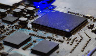
An SoC (system on chip) is a single integrated circuit that integrates multiple system functions.

Unlike conventional system designs that utilize multiple chips (such as microprocessors, memory, graphics devices, communication devices, etc.), an SoC combines these functions onto a single chip, resulting in a compact and high-performance system.

Uses of SoCs

SoCs are used in diverse applications, including smartphones, tablets, embedded systems, IoT devices, and automobiles. These chips serve as the central component in device control, enhancing multifunctionality and miniaturization.

1. Mobile Devices

SoCs are fundamental in mobile devices like smartphones and tablets, integrating various functions such as processing, graphics, memory, communication, and sensors onto a single chip.

2. Embedded Systems

Embedded systems across various sectors, including automotive, home appliances, industrial controls, and medical equipment, employ SoCs for their advanced functions and real-time processing capabilities.

3. IoT (Internet of Things) Devices

In IoT devices, SoCs provide critical functions such as sensing, communication, and data processing, offering advanced functionality and connectivity with minimal power consumption. This includes smart home devices, sensor nodes, and wearable technology.

4. Network Devices

Network devices, including routers, switches, and network security equipment, rely on SoCs for high-speed data processing and communication functions.

5. Audio/Visual Equipment

SoCs are also prevalent in audio/visual equipment like televisions, audio systems, and digital cameras, integrating various functions such as video and audio processing, and interfaces on a single chip.

6. Automotive Systems

In the automotive industry, SoCs are essential for in-vehicle systems, managing functions like vehicle control, driver assistance, entertainment, and communications to enhance comfort and safety.

Principle of SoCs

An SoC integrates all necessary functions into a single integrated circuit. Design data for each function is available either for free or at a cost. By selecting and connecting these functions using design tools, integrated circuits with desired functionalities are created. Circuit blocks available for integration include:

1. Microprocessor

Most SoCs include a microprocessor (CPU), enabling various functions through software.

2. Memory Devices

Memory devices are incorporated for CPU usage, including cache memory, RAM, and ROM, mainly for data and program storage.

3. Graphics Processing Devices

Graphics processing capabilities may be included, facilitating advanced graphics display, such as video playback, image processing, and 3D graphics.

4. Input/Output Interface

Various interfaces for connecting to external devices, such as USB, HDMI, Ethernet, and Wi-Fi, are provided.

5. Communication Functions

Communication functions supporting various protocols (e.g., Bluetooth, NFC, LTE) are often included for network connectivity and data transmission.

6. Sensor Signal Processing

SoCs may incorporate circuits for handling analog signals from devices like accelerometers, gyroscopes, and optical sensors, as well as A/D converters for digital data conversion.

The integration of these devices onto a single chip enables high-performance systems that are space-efficient and consume less power.

Other Information on SoCs

Development Process of SoC

The SoC development process involves several stages:

1. Function Selection and Design
The initial step is selecting the required functions and defining design specifications, including processors, memory, interfaces, network functions, and sensors.

2. Hardware Design
This stage entails designing specific circuits like digital circuits, analog circuits, memory blocks, and interface circuits, using techniques like schematics, flowcharts, and HDL (Hardware Description Language).

3. Chip Integration and Placement
After circuit design, hardware blocks are placed on a chip, including circuit interconnections, signal routing, and power routing. Advanced automated design tools are often used for efficient and reliable chip layouts.

4. Device Manufacturing
This involves semiconductor wafer fabrication, transistor, and circuit formation, and interconnect layer creation, culminating in the manufacturing and packaging of the IC chip.

5. Software Development
SoC development includes software creation, such as firmware, drivers, and application software, to complement the hardware functionalities.

6. Verification and Testing
The final stage involves verifying and testing the SoC, including circuit operation, signal accuracy, and system-level testing, to ensure quality and reliability.

These processes result in an SoC that integrates multiple functionalities into a single chip, achieving advanced system capabilities.