カテゴリー
category_usa

Whitworth Screw

What Is a Whitworth Screw?

Invented in England in 1841 by Whitworth, the Whitworth screw is distinguished by its 55-degree thread angle and triangular threads. As the first standardized screw type, it’s expressed in inches and marked with the symbol “W.” 

Usage of Whitworth Screws

Whitworth screws are integral to the waterworks and construction industries, where precision and reliability in fastening are paramount. Their design ensures higher accuracy and durability, making them suitable for applications demanding tight tolerances.

Characteristics of Whitworth Screws

These screws feature a unique 55-degree thread angle, differing from the 60° angle commonly found in metric and other inch screws. Their dimensions, including the outer diameter and thread pitch, are measured in inches, catering to specific engineering and manufacturing requirements.

Material and Surface Treatments

Materials for Whitworth screws vary, with selection crucial for ensuring strength and safety in critical applications. Protection against electrical corrosion is important, particularly when combining different metals like aluminum and stainless steel. Surface treatments are chosen based on corrosion resistance, aesthetic quality, and cost considerations.

Proper Use and Preventing Loosening

Proper use of Whitworth screws involves ensuring the tightening force and repetitive forces like vibration are within safe limits. It’s essential to prevent damage to the fastened objects and the screws themselves. Preventative measures against loosening include using loosening adhesives, double nuts, and specifically designed products to maintain the integrity of fastened objects, particularly in applications where safety is critical.
カテゴリー
category_usa

Magnetic Chuck

What Is a Magnetic Chuck?

Magnetic Chucks

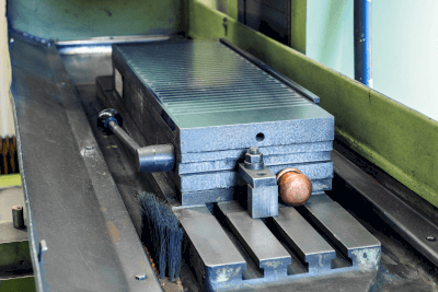
A magnetic chuck is a specialized device used in machine tools to securely hold metal workpieces. Featuring permanent magnets, it generates a magnetic force to keep the workpiece in place during machining operations, without needing an external power source. This design leads to significant energy efficiency and ease of use.

However, adjusting the magnetic force of a permanent magnetic chuck can be more challenging compared to electromagnetic chucks. It’s also important to note that the magnetic force may decrease in high-temperature environments.

Uses of Magnetic Chucks

Magnetic chucks are essential in various machining processes, particularly in:

1. Grinding

They are used in grinding operations for high-precision surface finishing of metal workpieces, such as in the production of gears and bearings.

2. Milling Machines

Magnetic chucks provide stability for workpieces in milling machines, aiding in detailed cutting and profiling.

3. End Milling Machines

They hold small metal parts securely in end milling machines, facilitating precision drilling and machining.

Principle of Magnetic Chucks

The principle behind magnetic chucks involves permanent magnets creating a steady magnetic force to hold the workpiece. This setup ensures stable, efficient, and energy-saving operation during machining, as it does not require an electrical power supply.

How to Select a Magnetic Chuck

Key considerations for selecting the right magnetic chuck include:

1. Size

Choose a chuck size that fits the workpiece, ensuring it sits securely on the chuck‘s surface.

2. Holding Power

Select a chuck with adequate holding force for the weight of the workpiece, ensuring safety and effective operation.

3. Flatness

For precision machining, opt for a chuck with high flatness accuracy to maintain quality in the finished product.

カテゴリー
category_usa

Panel Heater

What Is a Panel Heater?

Panel Heaters

Panel heaters are heating devices designed for use in electrical and control panels. They play a crucial role in protecting these panels from condensation and freezing, thereby extending the lifespan of electrical equipment. Often referred to as space heaters, panel heaters help maintain a stable temperature range, preventing damage or deterioration to electronic components and wiring caused by extreme temperature conditions.

Due to their use within electrical equipment, safety is a paramount consideration. Implementing safety measures like proper insulation, overheat protection, and overcurrent protection is essential.

Uses of Panel Heaters

Panel heaters find applications in various electrical devices and control panels, including:

1. Control Panels

In control panels responsible for managing industrial processes and machinery, panel heaters maintain a proper temperature, ensuring reliable control and preventing issues in cold environments.

2. Communications Equipment

These heaters are essential in communication and network equipment, where stable operating temperatures are needed to prevent condensation on components and ensure reliable operation.

3. Electrical Cubicles

Panel heaters are used in electrical cubicles and compact units for power distribution and protection. They maintain optimal temperatures for electronic components and circuits, preventing condensation and freezing.

Principle of Panel Heaters

Panel heaters typically operate on resistive heating. They employ a conductive heater element, often made of materials like nichrome alloys or stainless steel, which generates heat through resistance when electric current flows through it. This heat is then radiated to warm the surrounding air and objects.

The heater’s power supply is managed by a controller or control circuit, regulating the temperature through sensors and timers.

How to Select a Panel Heater

When selecting a panel heater, consider factors such as:

1. Output

The heater’s output should match the size of the electrical equipment and the conditions of the environment. Proper output ensures adequate heating.

2. Power Supply Requirements

Ensure compatibility with the voltage and frequency of the power supply. The electrical circuit and wiring should be designed accordingly.

3. Size

Choose a heater size that fits the dimensions of the electrical panel. Consider the installation space and wiring layout, as well as the installation method.

4. Controls

Select a panel heater with appropriate temperature sensors and control devices for effective temperature management and monitoring.

カテゴリー
category_usa

Straight Reamer

What Is a Straight Reamer?

Straight ReamersA straight reamer is a type of blade used in reaming, a process for high-precision hole finishing. It is similar to a spiral reamer, which serves the same purpose.

Reaming creates holes with predetermined dimensions and minimal diameter discrepancies. This is achieved through high-precision finishing after drilling the initial hole.

These reamers are suitable for manual (hand) reaming or machine-assisted reaming.

Reamers vary in material, shank size, tooth length, and cost, ranging from a few dollars to 150 dollars. Recently, reamers are often available at relatively low prices on auction sites.

Uses of Straight Reamers

For instance, when using a hand reamer, one first drills a pre-hole, ensuring the dimensions match the intended finished hole. It is advisable to consider the reamer diameter and workpiece material when selecting the finishing allowance.

The reamer is then passed through this pre-hole for high-precision finishing. To ensure straight passage, it is sometimes necessary to use tools like a square to keep the reamer perpendicular to the workpiece.

Hand reaming requires experience, as consistent rotation speed and feed rate are crucial for quality finishing.

Principles of Straight Reamers

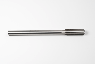
Straight reamers resemble drills with straight, lengthwise teeth. High-precision finishing is achieved by initially drilling a hole slightly smaller than the desired finished size and then passing the reamer through to remove the excess material, resulting in an accurately finished hole.

Compared to drilling, the allowance and blade shape of a reamer allow for a more accurate finish. However, there are factors to consider, such as the potential for slight surface cracking due to the straight blade. This can be influenced by clamping force, pre-drilled hole quality, cutting oil, and the rotation and feed rate. Manual machining requires significant experience.

The tooth shape of spiral reamers, used in similar applications differs. Spiral reamers have twisted teeth, producing facets directed from the tip of the machining section toward the hole’s entrance in the workpiece.

When selecting a new straight reamer, consider a variety of products from different manufacturers, ensuring compatibility with the workpiece to be machined.

カテゴリー
category_usa

Electric Lifting Device

What Is an Electric Lifting Device?

Electric Lifting DevicesAn electric lifting device is an apparatus powered by electricity that can raise, lower, and adjust the height of objects such as tables, chairs, and beds.
Widely used across various sectors, including factories, offices, and hospitals, these devices enable adjustment of working heights to suit user requirements. They are recognized for their health benefits, offering postural adaptability to match individual heights and preferences.

The device operates easily with a simple switch and is designed for safety, featuring an automatic stop function if an obstacle is detected by its sensors.

Uses of Electric Lifting Devices

Electric lifting devices find diverse applications in hospitals, factories, and offices.

In healthcare settings, they are utilized for patient examination chairs, tables, stretchers, nursing beds, and wheelchairs.

In industrial and office environments, they enhance the ergonomics of desks, worktables, and chairs, helping alleviate worker fatigue through adjustable heights. Additionally, they are employed in electric cylinders used on ships.

Types of Electric Lifting Devices

These devices range from multi-lifts (e.g., industrial work platforms) and slim, low-noise lifts, to highly rigid models designed for heavy loads.

There are also synchronized types that enable coordinated lifting and lowering, suitable for use with multiple units. Features include safety measures like automatic power shutdown in case of sensor-detected failures during operation, and automatic shutdown at end points. Below are details on various types and their features.

Stairlifts

Stairlifts are automated chairs that ascend or descend stairs. Suitable for both indoor and outdoor usage, they accommodate straight, curved, and various other staircase designs.

BL1 (LINAK: BL1)

These are 3-stage electric lifting devices with a maximum stroke of 16 inches, commonly used in healthcare settings for beds, chairs (such as examination and dental chairs), and examination tables. Their compact size and long stroke are notable features.

DL5 (LINAK: DL5)

These two-stage electric lifting devices are compact and primarily used in office desks and similar applications.

カテゴリー
category_usa

Cabinet Air Conditioner

What Is a Cabinet Air Conditioner?

A cabinet air conditioner is a cooling device specifically designed for control panels in industrial settings.

Control panels often contain heat-generating components like inverters and magnetic switches. While simple control panels can rely on natural heat dissipation, more complex panels with multiple heat-generating devices require active cooling to prevent overheating and potential failure of electronic components.

Cabinet air conditioners offer a solution by cooling the interior of control panels, thus enhancing the reliability and efficiency of the equipment they serve.

Uses of Cabinet Air Conditioners

Cabinet air conditioners are employed in various applications, including:

1. Telecommunication Equipment

Used in base stations and data centers where equipment operates under high loads for extended periods, generating substantial heat. Cabinet air conditioners maintain optimal operating temperatures.

2. Medical Equipment

In medical settings, precise temperature control is crucial for equipment like MRI machines. Cabinet air conditioners ensure safe and accurate operation by maintaining appropriate internal temperatures.

3. Factories and Industrial Facilities

These facilities use a range of equipment that often operates at high loads. Cabinet air conditioners cool control panels and equipment, improving reliability and ensuring production stability.

For instance, programmable controllers in industrial control panels typically operate within a temperature range of 0 to 40℃. Cabinet air conditioners help maintain this temperature range.

Principle of Cabinet Air Conditioners

Cabinet air conditioners operate on principles such as the compression refrigeration cycle and effective air distribution.

They use refrigerants to absorb and release heat through compression and expansion. The refrigerant, compressed in a compressor, releases heat at high pressure and then returns to low pressure through an expansion valve, absorbing heat from the surrounding air. Cooling fans also play a crucial role in promoting internal air circulation, drawing in outside air to expel heat and cool the internal components.

Types of Cabinet Air Conditioners

There are three main types of cabinet air conditioners: cooling fan type, heat exchanger type, and cooler type.

1. Cooling Fan Type

This type uses a cooling fan to draw outside air into the control panel. It’s cost-effective with good cooling performance but requires measures to prevent dust, like installing filters.

2. Heat Exchanger Type

It consists of a heat exchanger and internal and external air fans. The internal fan circulates air inside the panel, while the external fan helps exchange heat between the inside and outside air. More expensive than the cooling fan type, it offers less cooling capacity but is easier to maintain as it doesn’t introduce outside air.

3. Cooler Type

This type uses a compression refrigeration cycle for enhanced cooling. While it’s the most expensive and requires specialized maintenance, it offers the highest cooling capacity. If CFCs are used as refrigerants, regular legal inspections are mandated.

カテゴリー
category_usa

555 Timer IC

What Is a 555 Timer IC?

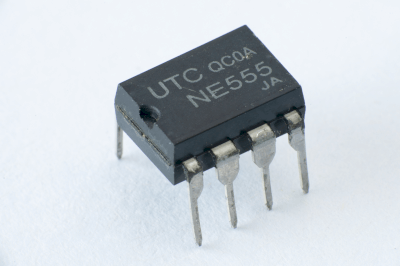
555 Timer ICsA 555 timer IC is commonly used as an oscillator in electronic circuits. It is well-suited for applications such as driving LED displays by supplying fixed-cycle pulses.

The XX555 is a popular variant of the 555 timer IC, with the ‘XX’ prefix varying by manufacturer. It is renowned among digital circuit designers for its reliability and versatility.

Indeed, it is one of the most iconic semiconductors in modern electronics.

Uses of 555 Timer ICs

555 timer ICs are widely used in oscillator circuits within digital systems, providing the main synchronization signal. These fixed-cycle signals are essential for microcontrollers and system controllers to synchronize their operations.

LED display circuits leverage the 555 timer IC for its ability to freely set display durations, making it versatile for various applications.

Furthermore, in digital circuit design, situations often arise where a signal of a fixed period and arbitrary frequency is needed. The 555 timer IC is highly advantageous in such scenarios due to its ease of use and flexibility.

Principles of 555 Timer ICs

The XX555 timer IC primarily comprises three circuits: a window comparator, an RS-flip-flop (RS-FF), and a charge/discharge circuit utilizing capacitors (C) and resistors (R). Its basic operation involves connecting the output of the window comparator to the RS-FF, and then to the charge/discharge circuit through an open collector transistor buffer. This setup creates a feedback loop essential for its functioning.

In the charge/discharge circuit, voltage is applied to the capacitor (C). When the capacitor’s charge reaches a specific voltage, the window comparator activates. As the voltage hits a predetermined level, the comparator’s output switches high, triggering the RS-FF and turning on the transistor buffer. This action initiates the discharge phase. The subsequent discharge causes the comparator’s output to switch low, resetting the RS-FF and resuming the charging phase.

This cyclic operation results in the NOT(Q) output of the RS-FF inverting at a set interval. Consequently, the 555 timer IC’s output (Q) also inverts to sync with NOT(Q).

カテゴリー
category_usa

Hardness Testor

What is a Hardness Tester?

A hardness tester is a device used to measure the hardness of materials, typically metals, by assessing their resistance to deformation. Hardness reference specimens, or standard specimens, play a crucial role in ensuring the accuracy of these measurements. They are test pieces with known hardness values used to calibrate and verify the performance of hardness testers.

Application of Hardness Testers

Hardness testing is critical in the metal manufacturing process, particularly in evaluating the effectiveness of heat treatments. It serves as a non-destructive quality control measure, offering insights into material properties such as tensile strength without the need for more costly and time-consuming tests. Hardness tests are essential for ensuring the desired mechanical properties in heat-treated parts and other components requiring specific hardness levels.

Principle of Hardness Testers

To maintain reliability, hardness testers must exhibit minimal hardness variation and remain stable over time. Materials like SKS3, SK85, C2600P, S10C, and S45C are commonly used.

Importance of Hardness Testers

Hardness testers offer a practical and economical alternative to direct strength tests in confirming material qualities. It is particularly useful for surface hardness measurements, where the minor marks left by the test can be easily removed in subsequent machining processes. Hardness is typically measured by the size of an indentation left by a defined indenter under a specific load, with results calibrated against known reference values.

Key Points in Hardness Testing

While hardness testers provide a range rather than an absolute value of hardness, they are indispensable for calibrating testers to ensure consistent and accurate measurements. These specimens undergo thorough heat treatment to prevent changes in hardness over time, although repeated use near previous indentations is discouraged to avoid work-hardening effects. The lifespan of a hardness tester is limited by the number of tests it can undergo before affecting its reliability.

カテゴリー
category_usa

SIM

What Is a SIM?

SIMs

SIM, an acronym for “subscriber identity module,” is a small chip that stores a user’s contact information and phone number. It is essential for connecting a cellular phone to a carrier’s network.

SIM cards have evolved, with recent versions becoming smaller and more electronic, such as nanoSIM and eSIM.

Uses of SIMs

1. Smartphones

Smartphones can use SIMs for voice calls and data communication; SIMs allow users to choose their own phone numbers and communication plans. When traveling abroad, you can also save on roaming fees by replacing your SIM with a local SIM.

2. Tablets

Tablets can be connected not only to Wi-Fi, but also to mobile networks using a SIM, which allows you to access the Internet, e-mail, and social networking services while on the go. If the tablet has voice-calling capabilities, the SIM can also be used to make phone calls.

3. Laptop Computer

Some laptops can also be connected to a mobile network with a SIM, allowing access to the Internet, online meetings, and remote work even when Wi-Fi is not available. If the laptop has voice capabilities, the SIM can also be used to make phone calls.

4. Surveillance Cameras

Surveillance cameras can transmit video and audio in real-time using a SIM, making it possible to install surveillance cameras even in locations without an Internet connection. The video and audio sent from the surveillance camera can be viewed on a smartphone or PC.

5. In-Vehicle Camera

An in-vehicle camera can transmit drive recorder video and location data using a SIM, which can be used as evidence in the event of an accident or other trouble, or to remotely check the status of a vehicle. The images and location information sent from the in-vehicle camera can also be viewed on a smartphone or PC.

6. Digital Signage

When a SIM card is inserted into the digital signage, it can be connected to a mobile network. This allows digital signage to display real-time information and change the display according to timing.

Principle of SIMs

A SIM card stores crucial information including:

  • IMSI (International Mobile Subscriber Identity): Identifies the carrier, country, and user.
  • ICCID (Integrated Circuit Card Identifier): The unique identification number of the SIM card.
  • Authentication Key (Ki): A secret key used for encrypted communications with the network.
  • SMS and Contact Information: Some SIM cards store messages and phonebook data.

During communication, a cell phone sends the IMSI number to the base station for user verification and plan authentication. Encrypted communication is then initiated using the authentication key (Ki).

Types of SIMs

SIM cards are available in various types, each with specific features and suitability for different devices:

1. Mini-SIM

Common in older iPhone models and Android smartphones, the Mini SIM is larger, offering flexibility in handset changes but limiting handset design due to its size.

2. Micro SIM

Smaller than the Mini-SIM, the Micro SIM is used in newer iPhone models and tablets. It allows for a more flexible device design but requires an adapter for compatibility with Mini SIM devices.

3. Nano-SIM

The smallest type, Nano-SIM, is used in the latest smartphones. It offers maximum design flexibility but lacks compatibility with Micro and Mini SIMs without an adapter.

カテゴリー
category_usa

Shaft Bracket

What Is a Shaft Bracket?

A shaft bracket is a component used for mounting, fixing, and holding parts related to a drive shaft or shaft. It enables the attachment of sensors and other parts to the drive shaft or shaft during assembly, modification, or maintenance of machinery.

The shaft bracket is designed as a two-part structure, allowing it to be disassembled and installed even when the drive shaft or shaft is already assembled into the machine.

Uses of Shaft Brackets

While the shaft bracket itself does not perform any direct function, it plays a crucial role in securing sensors and other components to the drive shaft or shaft.

Shaft brackets are used to hold the component in place, attaching it to the mounting holes of the brackets with bolts or similar fasteners.

There are two main types of shaft brackets: one for round shafts and another for square shafts, chosen based on the shape of the shaft.

Principles of Shaft Brackets

The principle of shaft brackets is straightforward. The bracket is fitted onto the drive shaft or shaft, and its two parts are bolted together to form a single unit.

In addition to securing the shaft, the brackets facilitate the attachment of a dog (a disk-shaped plate with a cutout), which is used in conjunction with a limit switch or sensor to detect rotation speed and set stop positions.

One of the two shaft brackets may be flanged for attaching a driven shaft to a flat part of another component. The version for square shafts is specifically designed for securing a shaft or mounting a sensor bracket.

Shaft brackets are typically made from cold-rolled steel sheet SP2C or stainless steel SUS304. The bolts, used for joining the two sections, are generally made of chrome molybdenum steel SCM435 or stainless steel SUS304.