カテゴリー
category_usa

Needle Nose Pliers

What Is a Needle Nose Plier?
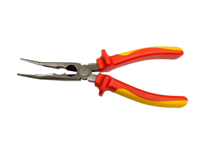
Needle Nose PliersA needle nose plier is a basic tool used in various fields, ranging from personal DIY projects to general business applications. While needle nose pliers have less gripping power than standard pliers or combination pliers, they are particularly useful in tight spaces. Their diverse tip shapes allow for selecting a tool that best suits specific needs.

There is a wide range of needle nose pliers available, from relatively inexpensive to high-end products, enabling users to choose the best fit for their requirements.

Uses of Needle Nose Pliers

Needle nose pliers feature long, slender tips with finely grooved cuts to grip objects securely. They are commonly used in heavy-duty tasks such as assembly and maintenance of industrial products, as well as for personal tasks like carpentry.

Typical applications include handling objects in narrow spaces, working with thin metal wires, and installing or removing small parts. Some needle nose pliers have a curved tip, which facilitates processing or gripping objects perpendicular to the insertion direction.

Principles of Needle Nose Pliers

The main advantage of needle nose pliers lies in their ability to manipulate small parts and process various types of wire, thanks to their long and narrow tips. Unlike radio pliers, they do not have a wire-cutting blade near the fulcrum, allowing for unobstructed gripping and precision. The finely engraved grooves at the tip ensure a firm grip, enabling the user to pull, push, turn, and pry objects effectively.

It is important to avoid twisting the tip like standard pliers or agitating it at the fulcrum, as this may deform the tip and impair its effectiveness. Also, leaving moisture on the fulcrum can cause rust and deterioration in movement. After use, cleaning with a parts cleaner and subsequent oiling or maintenance is recommended.
カテゴリー
category_usa

Photomicro Sensor

What Is a Photomicro Sensor?

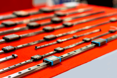
A photomicro sensor is a light-based device used to detect the presence, absence, and position of objects. As a form of optical sensor, they are notable for their small size and high sensitivity to light.

These sensors are compact, allowing easy integration into various devices, and enhancing both design and functionality. Their ability to detect light quickly makes them suitable for applications requiring rapid sensing. Additionally, they are effective in low-light environments, making them ideal for tasks like dark environment photography and environmental monitoring.

Photomicro sensors generally come in two types: transmission-type photointerrupters and reflection-type photoreflectors. They often utilize Infrared LEDs as light sources and are popular for their cost-effectiveness relative to their performance.

Applications of Photomicro Sensors

Due to their high sensitivity and compact design, photomicro sensors have a wide range of applications:

1. Cameras

Used in digital and smartphone cameras, these sensors detect light and capture images, even in dim conditions, producing high-quality results.

2. Automotive Driver Assistance

Photomicro sensors are key in automotive driver assistance systems for monitoring ambient light, aiding in headlight control, and providing driving assistance. They automatically activate headlights in dark conditions and help detect surrounding vehicles and obstacles.

3. Medical Equipment

In the medical field, these sensors are integral in devices like endoscopes, aiding in internal body observations and surgeries. They also assist in diagnosing tissue conditions through optical property measurements.

Principles of Photomicro Sensors

Photomicro sensors detect light and convert it into electrical signals. When light hits the sensor, it is absorbed by the semiconductor material inside, generating an electrical charge. This charge conversion process captures information about the light’s intensity and characteristics.

The semiconductor materials are typically sensitive to specific light wavelengths. When light enters the sensor, it excites electrons, which then move into the conduction band, creating a flow of electrical signals proportional to the light’s intensity and characteristics.

Types of Photomicro Sensors

Photomicro sensors are categorized into two types based on their operation:

1. Transmissive Photomicro Sensors

These sensors emit light from one side and receive it on the other, also known as photo interrupters. They detect objects passing between the emitter and receiver, offering high accuracy due to their straightforward design.

2. Reflective Type Photomicro Sensors

Also known as photoreflectors, these sensors measure by reflecting light off an object. The amount of reflected light received varies with the object’s position, allowing distance measurements.

カテゴリー
category_usa

Linear Guide

What Is a Linear Guide?

Linear GuidesA linear guide is a mechanical component that facilitates linear motion.
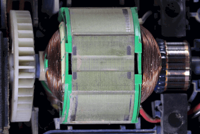
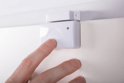
Similar products, such as LM guides, are also available in the market. Additionally, some linear guides come equipped with encoders, making them ideal for precision equipment like industrial robots.

Linear guides enable a block (movable base) to move back and forth along a rail with minimal resistance, ensuring consistent and smooth linear motion.

Uses of Linear Guides

Linear guides find extensive use across various industrial sectors, particularly in production facilities. Common applications include feeding workpieces in a straight line in manufacturing plants, facilitating linear movement of cylinders, and guiding workpieces for precise positioning. They are also used in automation, where mechanisms like link systems, stoppers, or reversing mechanisms are required.

Principles of Linear Guides

Linear guides typically consist of a rail, a block, and balls that facilitate movement. Most are equipped with seals to protect the moving parts from dust and other contaminants.

The interaction between the rail and block through the driving balls enables smooth linear motion. As the block moves along the rail, the balls roll on their respective surfaces, reducing friction and enhancing motion efficiency.

Integrating linear guides with encoders allows for precise position detection post-movement. When combined with feedback control and servo or stepper motors, they can achieve high-precision positioning.

Given their use in demanding applications like industrial robots, linear guides are available in various configurations. Options include guides with rollers instead of balls for increased rigidity, different sizes for diverse requirements, and guides designed for curved motion. These variations cater to specific needs and can be selected from manufacturers’ catalogs.

カテゴリー
category_usa

Network Array

What Is a Network Array?

A network array is a resistor network used in electronic circuits and sensors, comprising multiple resistor elements on a single substrate. This arrangement allows for high mounting density, efficient component placement, and cost reduction.

Typically, one end of each resistor in a network array connects to a signal line, and the other end to a common terminal, often serving as a pull-up resistor. This configuration is advantageous in various circuit designs.

Uses of Network Arrays

Network arrays find applications in diverse electronic settings, particularly for:

1. Resistor Dividers

Utilized in resistor dividers for analog-to-digital and digital-to-analog converters, network arrays play a critical role in signal processing.

2. Sensor Arrays

Used in temperature sensor arrays, they enable the detection of different temperature ranges, essential in precision sensing tasks.

3. Pull-up Resistors

Network arrays function as pull-up resistors in communication systems, especially between CPUs and memory, maintaining the integrity of data and address buses.

Principle of Network Arrays

Network arrays operate based on interconnected resistors:

1. General Resistor Network Array

Comprising resistors in series, these arrays create voltage drops for effective voltage division.

2. Sensor Array

As sensor arrays, they respond to physical changes such as temperature or pressure, providing vital resistance data for external analysis.

3. Pull-up Resistor

In I/O circuits, network arrays stabilize signal potentials in open-drain outputs, enhancing communication efficiency.

Structure of Resistor Array

The network array’s structure is integral to its function:

1. Substrate

A supporting insulating material, often ceramic, forms the foundation of the array.

2. Resistors

Thin-film resistors on the substrate are tailored for specific resistance values, crucial in precise circuit design.

3. Electrodes

Electrodes at each resistor’s ends facilitate electrical connections within the circuit’s wiring layout.

4. Packaging

Protected in chip resistor (SMD) or dual-inline (DIP) packages, network arrays are safeguarded for handling and use.

カテゴリー
category_usa

Brushless DC Motor Driver

What Is a Brushless DC Motor Driver?

A brushless DC motor driver is a semiconductor device that drives and controls a motor based on instructions from a microcontroller or another control unit.

Creating a drive circuit with semiconductor discrete components is possible. However, controlling brushless DC motors is complex, requiring many components and sophisticated software control.

Thus, motor drivers are often utilized to decrease software development efforts and component counts.

Applications of Brushless DC Motor Drivers

Brushless DC motor drivers are crucial for devices using brushless DC motors, enabling precise speed control. They find applications in hard disk drives, NC-controlled machines, automobiles, and hybrid vehicles.

Specifically, in automobiles, they are used for door lock motors, electric power steering motors, and headlight axis adjustment motors, among other applications.

Principle of Brushless DC Motor Drivers

In a motor, the electromagnet is stationary. By altering the current flow direction through the coil, it’s possible to change the electromagnets’ polarity, enabling attraction and repulsion.

Electronic control is necessary to drive a brushless DC motor. To rotate the motor, a rotating magnetic field is created by changing the current direction in the motor windings.

While induction motors, which operate on AC power, use AC voltage to generate a rotating magnetic field, brushless DC motors, operating on DC power, cannot employ the same method.

Unlike brushed DC motors, where commutators and brushes change the current direction, brushless DC motors use semiconductor switches, such as transistors, for this purpose.

Features of Brushless DC Motor Drivers

The benefits of using brushless DC motor drivers include comprehensive on-chip protection functions and reduced effort in developing microcontroller control software. Additional advantages are fewer components, minimized board mounting area, and simplified motor drive realization.

Moreover, while brushed DC motors rely on brushes for current direction control, necessitating periodic replacement due to wear, brushless DC motor drivers achieve brushless current control, offering a longer lifespan and lower maintenance.

Other Information on Brushless DC Motor Drivers

1. Coil Configuration of Brushless DC Motors

Brushless DC motors feature three coils, with one coil interconnected to the others, allowing current to flow through two coils by connecting one to the positive side and the other to the negative side.

Each coil connects to two semiconductor switches, with motor rotation achieved by sequentially controlling these switches. A brushless DC motor driver is essential for generating a rotating magnetic field and rotating the motor by sequentially controlling the semiconductor switches.

2. Relationship with Microcontrollers

A microcontroller is essential for controlling the timing and speed of motor rotation. However, most microcontrollers cannot directly control motors through their input/output ports.

In such cases, a motor driver facilitates motor control by mediating control signals between the microcontroller and the motor. Upon receiving a signal from the motor driver, the motor alters the polarity of each electromagnet to move the motor.

カテゴリー
category_usa

Stop Watch

What Is a Stopwatch?

A stopwatch is a measuring instrument used to measure time during various experiments or evaluations. It typically measures time from 0 seconds to 60 minutes in 1/100th of a second increments.

Standard features include a start button to begin timing, a stop button to end timing, and a reset button to clear the recorded time. The timer increments when the start button is pressed or counts down from a preset time, emitting an audible alarm when reaching 0 seconds. Some models also have a dial knob for easy time setting.

Uses of Stop Watches

Stopwatches are essential in troubleshooting, for instance, in product design. If a defect is known to occur within a specific period under certain conditions, accurately measuring this duration is crucial. Typically, the defect’s duration is measured by manually starting and stopping the watch, which may not be highly accurate. However, repeating the measurement several times and taking the average can provide reasonably accurate data. This method can identify delay times in circuits or response times, aiding in pinpointing the defective circuit part.

Principles of Stop Watches

A stopwatch consists of a battery, quartz crystal, liquid crystal display, and a system on chip (SoC). The SoC divides the oscillation pulses of the quartz crystal, counts them, and displays the time on the liquid crystal display.

Pressing a button on the watch sends a signal to the SoC, which identifies whether it is a start, stop, or reset command. The start button initiates timing, the stop button ceases it, and the reset button clears the internal timing data. The core component, the crystal unit, generates an oscillation frequency when voltage is applied, determined by the crystal’s shape. Common oscillation frequencies range from several hundred KHz to a hundred MHz, with an accuracy about 0.001%, significantly higher than ceramic resonators. Although more expensive, these crystals ensure precise timekeeping. A 32.768 KHz crystal, divided to mark one-second intervals, is typically used for timing.

カテゴリー
category_usa

Bearing Checker

What Is a Bearing Checker?

A bearing checker is a diagnostic device used to assess the condition of bearings.

Bearings are essential in supporting rotating machinery and minimizing friction. Their deterioration or failure can lead to significant equipment damage. A bearing checker helps detect early signs of bearing issues, enabling proactive maintenance and preventing extensive damage. These devices typically operate non-invasively, avoiding damage to the bearings during inspection. Regular use of bearing checkers can minimize production downtime and reduce repair costs. Many models are portable and user-friendly, simplifying on-site inspections.

However, accurate interpretation of bearing checker results requires understanding both the equipment’s operation and the characteristics of the bearings being examined. Results may be influenced by external factors, necessitating careful analysis.

Applications of Bearing Checkers

Bearing checkers are valuable for monitoring bearing conditions in machinery. Their main applications include:

1. Maintenance and Preventive Maintenance

These devices are instrumental in routine maintenance, allowing early detection of wear and potential failures. This proactive approach facilitates timely replacements and avoids unexpected breakdowns.

2. Failure Diagnosis

Bearing checkers are crucial for diagnosing malfunctions in machinery. They help identify issues such as abnormal vibrations or noises, indicative of wear or internal damage, thus guiding effective repair strategies.

3. Quality Control

In manufacturing, ensuring bearing quality is vital. Bearing checkers are used to inspect bearings during production, detecting defects early and maintaining product quality.

Principle of Bearing Checkers

Bearing checkers operate by analyzing vibration, temperature, and sound. They detect bearing abnormalities through the vibrations generated during rotation, measuring patterns in frequency and amplitude. Increased temperature, often a sign of wear or inadequate lubrication, is detected using infrared sensors. Additionally, sounds produced by bearings are analyzed for abnormal frequencies and patterns, indicating potential issues.

How to Select a Bearing Checker

Key factors to consider when selecting a bearing checker include:

1. Measurement Method

Options include ultrasonic or shock wave measurement methods, with some models offering both. Choose a method suited to the specific types of abnormalities you aim to detect.

2. Measurement Range

Ensure the checker’s measurement range aligns with the size and type of bearings used in your equipment. Larger or heavily loaded bearings may require a checker with an extensive range.

3. Power Supply

Consider the operating environment when choosing between battery-powered, rechargeable, or corded models. The power supply should match the portability needs and available power sources at the work site.

カテゴリー
category_usa

Brushed DC Motor

What Is a Brushed DC Motor?

Brushed DC Motors

A brushed DC motor is a type of DC motor equipped with brushes that facilitate current flow through the rotor.

These motors are known for their simple control mechanisms, allowing easy manipulation of rotation direction and speed. They offer high starting torque and operate effectively across a wide range of speeds. Brushed DC motors are also favored for their straightforward mechanics, making them ideal for educational purposes and beginners. Additionally, they are cost-effective to produce and purchase.

However, the brushes in these motors are prone to wear due to contact with the rotor, necessitating periodic replacement and limiting the motor’s lifespan.

Applications of Brushed DC Motors

Brushed DC motors are used in diverse applications, including:

1. Power Tools

These motors are a popular choice for power tools due to their high starting torque and compact design, making them suitable for drills and vibratory tools used in construction and repair work.

2. Toys

Used in radio-controlled cars, helicopters, model airplanes, and more, brushed DC motors are preferred for their affordability and ease of control, enhancing the enjoyment of various toys.

3. Handy Fans

Handheld fans, especially useful in hot conditions, often rely on brushed DC motors for efficient air movement at low power.

4. Home Appliances

Common in electric toothbrushes, hand mixers, and hair dryers, these motors serve as a reliable power source in many small household appliances.

Principle of Brushed DC Motors

Brushed DC motors operate by the interaction between an electric current and a magnetic field. Key components include the rotor, stator, and brushes.

The stator, typically a permanent magnet or electromagnet, surrounds the motor’s rotation axis. The rotor, attached to the motor shaft, contains coils. Brushes supply power to the rotor while maintaining contact.

Upon powering the motor, current flows through the rotor coils, turning them into electromagnets. This creates a magnetic field that interacts with the stator’s magnet, generating torque and causing the rotor to spin. The brushes ensure continuous current supply and direction variation, maintaining the rotor’s rotation.

How to Select a Brushed DC Motor

Key considerations when selecting a brushed DC motor include:

1. Voltage Rating

Ensure the motor’s voltage rating matches the intended power supply. Using the correct voltage is crucial, as overvoltage can damage the motor.

2. Power

Select a motor with sufficient power capacity to handle your required torque and load. Higher power capacity usually translates to more robust performance under larger loads.

3. Mounting Method

Choose a mounting method, such as shaft-mounted or flange-mounted, that suits your application. Consider the available space and connection requirements.

カテゴリー
category_usa

Door Sensor

What Is a Door Sensor?

Door Sensors

A door sensor is a device designed to detect the opening and closing of doors.

These sensors are commonly installed in the doorways of buildings and vehicles to monitor door movements. They play a crucial role in security systems by detecting unauthorized entries, often by triggering alarms if a door is forcibly opened or opened at unusual times. Door sensors also facilitate the operation of automatic doors in high-traffic areas, promoting efficiency and convenience.

However, some door sensors may trigger false alarms or unintended automatic operations due to environmental vibrations or changes.

Uses for Door Sensors

Door sensors have a wide range of applications, including:

1. Automatic Doors

These sensors enable doors to open and close automatically as people approach, often using infrared or ultrasonic waves to detect movement. Common in public facilities, commercial buildings, and hospitals, they offer barrier-free access and smooth traffic flow.

2. Security

Door sensors enhance building security by monitoring door activity. They can trigger alarms during unauthorized entries or after-hours access.

3. Access Control

In access control systems, door sensors enhance security by allowing entry only to authorized individuals, often using smart cards or biometric recognition.

Principle of Door Sensors

Door sensors function by detecting physical changes associated with door movements. When a change is detected, the sensor generates a corresponding signal, such as a ‘close’ signal when the door closes or an ‘open’ signal when it opens. These signals are relayed to security or automatic control systems to initiate appropriate actions, like activating alarms.

Types of Door Sensors

Various types of door sensors are available, each operating on different principles:

1. Magnetic Sensor

Magnetic sensors use magnets attached to both the door and frame. Contact between the magnets indicates a closed door. Simple and durable, these sensors are widely used in diverse settings.

2. Light Sensor

Light sensors use infrared beams to detect door movements. When the door closes, the light beam reaches the sensor directly, but it is interrupted when the door opens. These non-contact sensors are suitable for automatic doors and security systems.

3. Pressure Sensor

Pressure sensors detect changes in pressure caused by door movements. Installed on the door, they sense pressure differences when the door opens or closes. Durable and effective, they are often used in harsh outdoor environments.

カテゴリー
category_usa

Inch Screw

What Is an Inch Screw?

Inch ScrewsAn inch screw is a type of screw with dimensions standardized in inches.

While metric screws, standardized in meters, are commonly used in Japan, inch screws are prevalent in the United States, the United Kingdom, and Canada.

Uses of Inch Screws

Inch screws are utilized in various applications, including:

  • Civil engineering and construction: electrical, plumbing, air conditioning, and piping systems.
  • PC components: hard disks, chassis cases.
  • Precision equipment: cameras.
  • Music equipment: drums, speakers.

They are also used in aircraft manufacturing and imported furniture.

Principles of Inch Screws

The functioning principle of an inch screw is similar to that of a standard screw. It uses its inclined plane to lift heavy objects, generating a significant fastening or axial force. The screw stays tight due to the frictional force on its slope, which exceeds the gravitational force acting on it, thus maintaining the fastening force without loosening.

Types of Inch Screws

Inch screws are primarily classified into two categories: unified threads and wit screws.

1. Unified Threads

Unified threads are standards defined by the American National Standards Institute (ANSI). They come in two types: unified coarse threads and unified fine threads. The fine threads have a smaller pitch than the coarse threads and are less prone to loosening but require more turning during fastening. Metric screws also come in similar coarse and fine types.

2. Wit Screw

Wit screws are considered the world’s first standardized inch screws. Differing from metric and unified screws, which have a 60° thread angle, Witt screws feature a 55° thread angle.

Other Information on Inch Screws

1. Handling Precautions

Handling inch screws requires the same precautions as metric screws. However, extra care is necessary to avoid misuse, such as mistakenly using a metric screw in an inch screw hole. It is challenging to visually distinguish between metric and inch screws; therefore, measuring the outside diameter and pitch with calipers is recommended. If there is difficulty when tightening a screw into an unknown threaded hole, it is advised to measure the screw rather than forcing it.

2. Notation of Inch Screws

Inch screws are typically denoted by the following conventions: Coarse-grained screws are abbreviated as UNC, and fine-grained screws as UNF. The notation includes the screw nominal (thickness), number of threads, standard, and length. An example notation is 1/4-25UNCx5/8. Wit screws are indicated by adding “W” to their notation.