カテゴリー
category_es

Microscopio de Medición

¿Qué son los Microscopios de Medición?

Los microscopios de medición son máquinas de medición dimensional que miden dimensiones a partir de imágenes ampliadas por un microscopio.

Se componen de un microscopio óptico ampliado con un aumento exacto y una platina XY para desplazar con precisión la pieza de medición sobre una superficie plana, incluida una plantilla para la medición comparativa. Los microscopios de medición permiten la medición sin contacto y, por tanto, la observación de contornos y superficies sin dañar la pieza de trabajo.

Los microscopios de medición suelen utilizar ópticas telecéntricas en el sistema óptico. En los últimos años, algunas especificaciones han adoptado un sistema óptico corregido al infinito en el cabezal óptico para permitir la observación por interferencia diferencial y la observación sencilla con luz polarizada.

Usos de los Microscopios de Medición

Los microscopios de medición se utilizan para la producción y el control de calidad de piezas de máquinas relativamente pequeñas, piezas de dispositivos electrónicos y productos semiconductores. Los microscopios de medición son adecuados para medir piezas pequeñas y áreas pequeñas que son difíciles de medir sin el aumento del microscopio.

Además de la medición dimensional, el microscopio también puede utilizarse para la observación mediante luz polarizada e interferencia diferencial, por ejemplo, para detectar defectos en sustratos semiconductores. Debido a la precisión del aumento, también es útil para inspecciones sencillas para determinar si un producto está dentro de la tolerancia mediante mediciones comparativas utilizando una plantilla.

Los microscopios de medición pueden utilizarse como máquinas de medición y como microscopios, y un microscopio puede utilizarse para diversas aplicaciones.

Principio de los Microscopios de Medición

Los microscopios de medición pueden clasificarse según el método de iluminación.

1. Transiluminación

La iluminación transmitida se utiliza para la medición dimensional mediante la transmisión de luz y la captura de la sombra de un objeto como una forma de contorno. Se utiliza para medir contornos.

2. Iluminación Vertical Reflejada

La iluminación vertical reflejada emite luz perpendicular a la superficie de un objeto y utiliza la luz reflejada para observar la superficie. La iluminación vertical reflejada puede utilizarse no sólo para mediciones dimensionales, sino también para observar la geometría de la superficie.

3. Iluminación por Reflexión Oblicua

La iluminación por reflexión oblicua es un método de iluminación en el que la luz se proyecta en ángulo sobre la superficie del objeto de medición. La característica es que se acentúa el contraste de la imagen, de modo que puede obtenerse una imagen tridimensional y nítida. Sin embargo, es más probable que se produzcan errores en las mediciones dimensionales.

Más Información sobre los Microscopios de Medición

1. Óptica Telecéntrica

La mayoría de los microscopios de medición utilizan ópticas telecéntricas para la transiluminación. Los microscopios sin óptica telecéntrica hacen que los objetos cercanos parezcan más grandes y que los objetos lejanos parezcan más pequeños.

Este fenómeno es el mismo para las cámaras que utilizamos en nuestra vida cotidiana. Sin embargo, esta característica da lugar a mediciones dimensionales en las que los objetos lejanos se miden más pequeños en relación con diferentes partes en la dirección de la altura.

En los objetivos con óptica telecéntrica, la imagen aparece borrosa pero el tamaño sigue siendo el mismo, aunque el enfoque se desplace en la dirección de la distancia al objetivo y al eje óptico. Las ópticas telecéntricas son indispensables para los microscopios de medición, en los que las dimensiones se miden mientras se observa con el microscopio.

2. Paralelización de los Microscopios de Medición

Los microscopios de medición miden colocando el objeto de medición en una platina XY. Por lo tanto, el punto de medición puede estar en cualquier lugar dentro del rango operativo de la platina XY. Esto significa que la platina XY puede desplazarse hasta el punto de medición allí donde se encuentre el objeto de medición en la platina XY.

Algunos ángulos y diámetros circulares a medir requieren un gran movimiento de la platina XY, pero el contorno del objeto de medición nunca se coloca paralelo al movimiento de la platina XY sin un ajuste especial. Por lo tanto, es necesario poner en paralelo el movimiento de la platina XY con el borde de referencia del objeto de medición antes de la medición.

Si el objeto de medición y la platina XY no son paralelos, pueden producirse grandes errores al medir los ángulos y el paralelismo. Por lo tanto, es necesario realizar cálculos para compensar los resultados de la medición. En los últimos años, los fabricantes han desarrollado una gama de dispositivos de medición que crean un sistema de coordenadas en la platina XY y calculan a partir de las coordenadas del origen y los puntos de medición. El uso de estos dispositivos permite reducir las horas de trabajo necesarias para la paralelización.

3. Campo de Visión del Microscopio de Medición

Es importante que el microscopio pueda observar el objeto con un gran aumento, pero también es importante que se pueda obtener un amplio campo de visión de una sola vez. El campo de visión es la superficie que puede verse de una sola vez con el microscopio y viene determinado por el diámetro del ocular.

El tamaño del campo de visión se denomina número de campos de visión, y el campo de visión real es el área de la superficie del objeto que se está midiendo que es visible dentro del campo de visión. La relación entre el campo de visión real y el aumento del objetivo es la siguiente:

Campo de Visión Real = Número de Campos de Visión del Ocular / Aumento de la Lente Objetivo

Como se desprende de la fórmula anterior, si el número de campos visuales del ocular es el mismo, la gama del campo visual real se estrecha a medida que aumenta el aumento de la lente objetivo. Esto demuestra que existe un equilibrio entre el aumento de la lente objetivo para ampliar el objeto medido y el alcance que puede verse de una sola vez.

Para aumentar el campo de visión real, debe aumentarse el diámetro del ocular o reducirse el aumento de la lente objetivo. Sin embargo, la reducción del aumento de la lente objetivo tiene un límite debido al aumento necesario para la medición. Por este motivo, los microscopios de medición están equipados con una platina XY y un contador o dispositivo similar que muestra la cantidad de movimiento y mide la parte del objeto que no puede verse en el campo de visión.

カテゴリー
category_usa

Handle Automation Unit

What Is a Handle Automation Unit?

A handle automation unit is designed to automate the manual positioning of products on production lines and adjust production processes through the automation of handle turning. This automation aims to reduce human error and enhance production efficiency, as poor manual positioning can lead to incorrect product processing on the production line.

These units allow for process management via a PC, enabling the automatic and simultaneous control of handle operations. Typically, these units are controlled wirelessly, eliminating the need for wiring connections between devices.

Uses of Handle Automation Units

Handle automation units are primarily used to control the setup of factories and production lines. Manual operation of handles, especially in hard-to-reach areas, can increase the physical strain on workers, potentially impacting their health. By implementing handle automation units, this physical burden can be significantly reduced. Additionally, automating these processes decreases the risk of human error, which can be crucial for improving productivity.

Principles of Handle Automation Units

Handle automation units can easily replace conventional manual ones and can be integrated for immediate automation. Being wireless, these units are particularly advantageous in factory settings where wiring can be a concern. Moreover, multiple units can be controlled by a single receiver, which greatly reduces setup time and boosts productivity.

Once installed, handle automation units facilitate operations at various elevations or in environments with obstacles, reducing the physical exertion for operators and minimizing the risk of human error. Some units are designed to be waterproof and dustproof, making them suitable for use in harsh production line environments. A key feature of these units is their cost-effectiveness and time efficiency, as the software for automation is pre-developed.

カテゴリー
category_usa

Parallel Chuck

What Is a Parallel Chuck?

A parallel chuck is a type of chuck with a parallel open/close mechanism, primarily used for workpiece transfer.

The parallel chuck grips the workpiece at the center, functioning similarly to a three-jaw scroll chuck used in machine tools such as machining centers and CNC lathes, but it is essentially a two-jaw structure, resulting in a more compact design.

As hand jaws can be attached to the fingers to match the shape of the workpiece, the chuck is highly versatile.

Uses of Parallel Chucks

Parallel chucks are commonly used in workpiece transfer machines due to their lightweight and compact features. They are often used in loader machines connected to machine tools for supplying workpieces. Their low weight makes them suitable for high-speed loaders with strict maximum weight restrictions.

The shape of workpieces that can be gripped depends on the stroke of the fingers and the hand jaws to be installed, but cylindrical shaft material is typically suitable.

Principles of Parallel Chucks

Generally, parallel chucks operate using compressed air supplied from an air compressor. An air cylinder is built inside the chucks, and the air cylinder is mechanically connected to the fingers via driving rollers. When air is supplied from the air supply port, the piston of the air cylinder is pushed, causing the driving roller to push the fingers closed. A single air supply port is called a “single acting type.”

Some models have multiple air supply ports and are known as “double-acting types.” With the double-action type, the gripping force can be adjusted depending on the air supply port used.

As an air chuck, it tends to have higher repeatability (±0.01 mm or so) compared to hydraulic or manual chucks. However, due to its compact structure, it is less suitable for clamping heavy workpieces.

カテゴリー
category_usa

Bearing Balls

What Is a Bearing Ball?

Bearing BallsA bearing ball is an essential mechanical element used in various industrial products. It plays a crucial role in supporting rotational motion.

The balls are integral components of bearings, contributing significantly to the accuracy of rotational systems. In bearings, their precision directly affects the performance and efficiency of the industrial products in which they are used.

Low precision in bearing balls can impede rotation, compromising the functionality and efficiency of industrial products.

Uses of Bearing Balls

Bearing balls are found in devices such as CD and DVD players, and recording and playback equipment. Inaccuracies in these balls can lead to noise during recording or playback, or even result in incorrect functioning. For hard disks in PCs and similar devices, the precision requirement for bearing balls is even higher, particularly as storage capacity increases.

As essential components of bearings for various rotating parts, bearing balls are used in a wide range of applications, from small everyday items like ballpoint pens to components in automobiles and other vehicles.

Principles of Bearing Balls

Bearing balls are characterized by their perfect spherical shape. Any irregularity, even minimal, can increase resistance during rotation, affecting the product’s functionality or efficiency. Irregularities can also subject the bearing to unintended forces, potentially leading to malfunction or damage.

For industrial products under significant stress, durable materials like stainless steel are often used. Bearing balls are also made from materials like resin or aluminum, depending on the usage conditions.

The accuracy of a bearing ball is determined by its diameter consistency and surface smoothness. The closer the average diameter is to the maximum and minimum diameters, the more precise the ball. Sphericity is a measure of surface roughness, with smaller values indicating higher accuracy. Ball accuracy is classified by grades based on shape and surface roughness; a lower grade signifies higher accuracy.

カテゴリー
category_usa

Pine Tap

What Is a Pine Tap?

A pine tap is a processing tool designed for threading the female threads of both parallel and tapered pipe threads, which are used for connecting or joining pipes.

Pine taps are classified into two categories: parallel thread taps and tapered thread taps. Parallel thread taps are used for machining threads that are mainly intended for mechanical joints, while tapered taps are used for machining threads that need to be watertight and airtight, such as water and gas pipes.

Given the variety of standards for pine taps depending on the piping type, the thread standard, thread diameter, and pitch are selected according to the purpose of processing.

Principles of Pine Taps

Unlike standard parallel taps, pipe taper taps require cutting even on the fully threaded part, which results in high frictional resistance and requires 2 to 3 times the cutting torque of a hand tap.

The machining of pine tapered thread requires the proper setting because the diameter of the entrance varies depending on the machining depth of the tap.

Depending on the thread length required by the drawing, the tap may be a long or short thread, or a special tap may be used to process even shorter thread lengths.

In the case of the PT1/8-28 TPT long-threaded taper tap, the reference diameter position is approximately 13 mm.

In the case of taper tap PT1/8-28 S-TPT short-thread type, the reference diameter position is approx. 10.5 mm (0.4).

When a tap is replaced, if the same machining depth is used as before, it may not pass the taper thread gauge for pine taps. Therefore, when replacing a taper tap with a new one, it is necessary to make a shallow relief cut based on the reference diameter position each time, and adjust the cutting depth to pass the gauge while checking with the gauge.

カテゴリー
category_usa

Wrapping Machine

What Is a Wrapping Machine?

A wrapping machine is a machine used to automatically wrap sealing tape. It is commonly employed in industrial and manufacturing settings. The sealing tape, made of thin fluoroplastic, about 0.1 mm thick, adheres firmly to the unevenness of the threads, ensuring a secure seal even under pressure.

Compared to manually winding the sealing tape, a wrapping machine significantly enhances work efficiency. Its advantage lies in the ability to perform fast and accurate winding, allowing the completion of numerous tasks in a short time, thereby facilitating the meeting of tight deadlines.

Notably, some small parts with male threads are available with sealing tape pre-wrapped, presenting an alternative purchasing option.

Uses of Wrapping Machines

Wrapping machines find utility in several industries, as outlined below:

1. Construction Industry

In the construction industry, wrapping machines are vital for the sealing of piping connections, such as water pipes and heating systems. These seals are crucial for preventing leaks, ensuring building safety, and enhancing energy efficiency.

2. Industrial Plants

Industrial plants, especially those handling complex chemicals, rely on wrapping machines for leak prevention in their piping systems. This is essential for the safety of chemical processes and environmental protection.

3. Food Processing

In food processing industries, wrapping machines are integral for maintaining hygiene and quality control, particularly in preventing liquid leaks.

4. Agriculture

For agricultural watering and irrigation systems, effective sealing provided by wrapping machines is key for water conservation and efficient operation.

Principle of Wrapping Machines

The wrapping machine operates by wrapping the sealing tape around the screw connection multiple times while pulling the tape, and then cutting it with a cutter. This method ensures that the tape is applied without shifting or rolling up, and prevents backward winding, thus achieving optimal sealing.

There are two types of wrapping machines: semi-automatic and fully automatic. The semi-automatic type requires manual positioning of the threaded part, while the fully automatic version is equipped with a workpiece transfer device, utilizing a feeder and manipulator for automated tape application.

How to Select a Wrapping Machine

When selecting a wrapping machine, consider the following factors:

1. Power Supply and Drive Source

Verify compatibility with the available power supply in terms of voltage and frequency. Choose a drive source (electric or air motor) suitable for the working environment.

2. Sealing Tape Width

Select a machine that can handle the required width of sealing tape for effective application.

3. Winding Speed

Consider the winding speed relative to work efficiency and accuracy. A balance between speed and precision is crucial.

4. Compatible Thread Size

The machine must accommodate the size of the threads and the diameter of the connections to ensure proper sealing tape application.

カテゴリー
category_usa

PLD (Programmable Logic Device)

What Is a PLD (Programmable Logic Device)?

A PLD (programmable logic device) is an integrated circuit that allows the user to define and modify the internal logic circuitry after manufacturing.

Compared to ASICs (application-specific integrated circuits) and ASSPs (application-specific standard products), PLDs offer greater design flexibility and lower cost. For this reason, PLDs are widely used in a variety of electronic devices.

There are various types of PLDs, including FPGAs (field programmable gate arrays) and CPLDs (complex programmable logic devices). A CPLD has fewer gate arrays than an FPGA but is less expensive.

Uses of PLDs (Programmable Logic Device)

PLDs are widely used in a variety of industries due to their flexibility and efficiency. Specific use cases include:

1. Telecommunications Industry

In the telecommunications industry, PLDs are used for rapid hardware redesign to adapt to new communication standards, thus speeding up time-to-market.

2. Automotive Industry

The automotive industry uses PLDs to shorten development cycles for advanced driver assistance systems and in-car experiences and to meet safety standards in hybrid and electric vehicles.

3. Consumer Electronics Industry

PLDs are used in home appliances to support various video standards and to add AI functions.

Principle of PLDs (Programmable Logic Devices)

The principles of PLDs involve understanding their internal structure and hardware description language (HDL).

1. Internal Structure of PLDs

The basic internal structure of a PLD consists of programmable logic gates and connections. Logic gates perform specific logical operations (AND, OR, etc.) on input signals.

Some PLDs range from basic gate-level devices, like Programmable Array Logic (PALs), to more advanced devices like CPLDs and FPGAs.

2. Hardware Description Language

HDLs, such as VHDL and Verilog, are used to program PLDs, allowing precise descriptions of hardware behavior and its simulation.

Types of PLDs (Programmable Logic Device)

PLDs are classified into various types based on their structure and programmability, including:

1. PLA (Programmable Logic Array)

A PLA is a basic PLD with a programmable array of logic gates.

2. PAL (Programmable Array Logic)

PALs have a programmable AND array and a fixed OR array, suitable for simple circuits.

3. CPLD (Complex Programmable Logic Device)

CPLDs, with more gates than PALs, are suitable for larger digital systems.

4. FPGA (Field Programmable Gate Arrays)

FPGAs are advanced PLDs with up to millions of programmable logic gates, used for large digital systems.

カテゴリー
category_usa

Serpentine Belt

What Is a Serpentine Belt?

Serpentine BeltsA serpentine belt is a type of belt that combines elements of a V-shaped belt and a flat belt. Known for its high conductivity and excellent flexibility, this high-performance belt is used in various machines. Its low weight and minimal heat generation during operation facilitate high-speed rotation. Additionally, it offers the benefits of low vibration and noise. It is particularly suitable for machines requiring high-speed rotation, high conductivity, and a compact design.
Uses of Serpentine Belts

Serpentine belts are utilized in a diverse range of machinery, from industrial equipment to home healthcare devices. Due to their high conductivity, low heat and noise generation, these belts are ideal for applications that involve high-speed rotation, such as automobile engines. Their efficiency enhances the compactness of the entire machine. They are also used in machine tools and healthcare equipment where smooth, low-vibration, and quiet rotary motion is essential.

Principles of Serpentine Belts

The serpentine belt, a fusion of V-shaped and flat belt elements, features a distinct structure and characteristics.

Its structure comprises four main components: the upper fabric, core wire, adhesive rubber, and ribbed rubber. The flat belt aspect includes the upper fabric for protection and the core wire made of synthetic fiber for stability. The V-shaped element consists of ribbed rubber, which offers excellent pressure and compression resistance. The serpentine belt’s design is completed by combining these elements using strong adhesive rubber.

Key features of the serpentine belt include:

  • High Transmission Efficiency:
    With an approximate transmission efficiency of 98%, the belt efficiently transmits force and motion, making it ideal for high-speed rotation applications such as engines.
  • Capability for High-Speed Rotation:
    The belt’s lightweight nature and low heat generation allow for high-speed rotation.
  • Compact Design:
    The use of serpentine belts enables compact and energy-efficient equipment design.
カテゴリー
category_usa

Polyurethane Bearing

What Is a Polyurethane Bearing?

Polyurethane Bearings

Polyurethane bearings are bearings made primarily of urethane resin (polyurethane). These bearings reduce friction between mechanical parts and support rotating shafts, enabling smooth rotation and precise motion. Polyurethane bearings are known for their high wear resistance and longevity, maintaining performance over extended periods. They are also lightweight, contributing to reduced component weight and improved energy efficiency. With a smooth surface and low friction operation, they enable efficient movement of moving parts.

Chemically stable, polyurethane bearings are suitable for corrosive environments but have a lower load-carrying capacity compared to metal bearings, necessitating careful design and selection.

Applications of Polyurethane Bearings

Polyurethane bearings are versatile, and used in various applications due to their specific characteristics:

1. Light-Load Mechanical Parts

These bearings are ideal for lightweight mechanical parts, such as rollers in conveyors, where lightweight and low friction are crucial for transporting products and materials.

2. Low-Speed Moving Parts

Suitable for low-speed moving parts, polyurethane bearings are utilized in mechanical fingers for product insertion and assembly, providing smooth motion and precision during low-speed operations.

3. Food and Medical

In food processing machinery and medical equipment, the sound-absorbing properties of urethane make these bearings suitable for applications requiring vibration and noise control. This minimizes impact on the working environment and maintains cleanliness and smooth motion in food and medical equipment.

Principle of Polyurethane Bearing

Polyurethane bearings operate by reducing friction and providing support based on their properties. Urethane resin is flexible, elastic, and typically has a low coefficient of friction, allowing for smooth motion and minimal energy loss. Additionally, urethane’s ability to absorb vibration and shock helps reduce noise and vibration during operation, making these bearings ideal for quiet work environments or applications where vibration minimization is critical.

While suitable for light loads, low-speed motion, and vibration/noise control, polyurethane bearings require appropriate materials and designs for high loads and high-speed operations.

How to Select Polyurethane Bearings

Consider the following when selecting polyurethane bearings:

1. Urethane Hardness

The hardness of the polyurethane affects wear resistance and load capacity. Harder urethanes offer higher wear resistance, while softer ones provide better shock absorption. Choose hardness based on the application, with harder urethanes for load-bearing applications and softer for vibration absorption.

2. Urethane Types

Different types and compositions of urethane are available. Select based on characteristics like oil resistance, abrasion resistance, and quiet operation.

3. Operating Temperature

Consider urethane’s heat resistance limits, as it may deform or deteriorate in high temperatures. Choose polyurethane suitable for the operating temperature or consider alternative materials if necessary.

4. Dimensions

Proper dimensions, including shaft diameter, outside diameter, and width, are crucial for ensuring smooth operation and correct mounting within the equipment.

カテゴリー
category_usa

Knock Pin

What Is a Knock Pin?

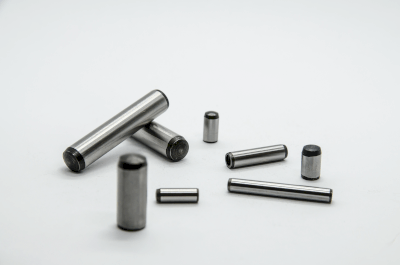
Knock PinsA knock pin is a type of jig specifically used to ensure the assembly accuracy of industrial products.

Knock pins are employed in joints requiring particularly high assembly accuracy during overhaul of industrial products, and in addition to serving as guides during jointing, they prevent misalignment during assembly and misalignment caused by external shocks.

Typically, two knock pins are utilized for each joint.

Uses of Knock Pins

Knock pins are utilized for joining parts that necessitate high-precision positioning. In particular, they are often used in automotive parts.

Specific uses of knock pins are as follows:

In addition, knock pins are also used on the mating surfaces of rotating parts, drive parts, and other parts that transmit power.

Principles of Knock Pins

Knock pins are designed to prevent misalignment in the radial direction (perpendicular to the axis). Generally, a single knock pin will cause misalignment at its fulcrum, so two or more pins are used at equal or diagonal intervals. Since the pin diameter tolerance is set only on the positive side and the use of press-fitting is assumed, a more precise assembly can be performed than with parallel pins.

Other Information on Knock Pins

1. Precautions for Using Knock Pins

When removing and reinstalling parts with knock pins, the knock pins may be pulled out together. When reassembling, it is necessary to check that the knock pins are properly inserted all the way to the back before reassembling.