カテゴリー
category_usa

Tungsten Machining

What Is Tungsten Machining?

Turning

Tungsten machining refers to the processing of tungsten, a metal known for its high melting point and hardness. This metal’s name is derived from the Swedish word for heavy stone. It exhibits a silver-gray color and is characterized by metallic stability and high electrical resistance. Tungsten’s exceptional heat resistance makes it ideal for ultra-high temperature applications, such as in heat treatment furnaces, while its low thermal expansion and high shape stability at extreme temperatures are noteworthy.

Uses of Tungsten Machining

Machining tungsten is crucial in industries requiring mechanical stability, including industrial and medical sectors. Despite the challenges posed by its hardness, tungsten’s applications range from electromagnetic wave sources in microwave ovens to weights in fishing and sports equipment, and its radiation shielding properties are valuable in medical devices. Though once common in incandescent light bulb filaments, tungsten has largely been supplanted by LEDs.

Types of Tungsten Machining

Machining methods for tungsten include turning, milling, and tapping, each with specific considerations:
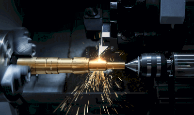
1. Lathe Turning

Surface roughness in lathe turning varies with the insert material. Cermet inserts, known for their larger rake angle and lower cutting resistance, produce finer finishes, whereas cemented carbide inserts, with their smaller rake angles, result in rougher textures due to thicker chip formation and higher resistance.

2. Milling

For milling, a combination of wet roughing to reduce speed and dry finishing ensures stable surface quality, as wet finishing can lead to inconsistencies.

3. Tapping

Tapping a challenging material such as tungsten requires careful control of the feed rate to prevent tap breakage, with planetary cutters recommended after initial drilling to shorten machining time.

How to Select Tungsten Machining

Selection criteria for machining tungsten involve choosing the appropriate tools and processes to mitigate its inherent processing challenges. Recommendations include using cermet inserts for smoother lathe turning surfaces, wet roughing and dry finishing in milling for optimal surface quality, and employing planetary cutters for efficient tapping.

Structure of Tungsten Machining

Tungsten, symbolized as W and with an atomic number of 74, boasts the highest melting point among metals at 6,192 °F (3,422 °C) and the lowest coefficient of thermal expansion. Its density, comparable to gold, and superior radiation shielding capabilities make it preferable to lead in medical and industrial applications. Tungsten’s combination with carbon forms tungsten carbide (WC), a compound with a Mohs hardness of 9, extensively used in cutting tools for its exceptional hardness.

カテゴリー
category_usa

Measuring Gage

What Is a Measuring Gage?

Measuring gage is a general term for a measuring tool that has a standard dimension, angle, shape, etc. It is mainly used in the manufacturing process to quickly determine whether a machined dimension, etc. is acceptable or not.

It is mainly used in the manufacturing process to quickly determine if the machined dimensions, etc. are acceptable or not. Measuring gages are not calipers or micrometers that measure dimensions. It is a tool to determine whether the dimensions of the object to be inspected are within the standard range.

When measuring dimensions with a measuring instrument, the speed and quality of the inspection process can vary depending on the skill level of the inspector. However, using a measuring gage, it is easy to determine whether a product is acceptable or not. Differences in operator skill are less likely to appear, and the gauges are easy to handle.

In addition, measuring gages can be used not only for on-site inspections but also for quality control between different companies. Simply by passing the same gauges to the subcontractors and telling them to use the gauges for quality control, the same dimensional control can be performed between the two companies.

Uses of Measuring Gauges

Measuring gages are used in the production line of industrial products. They are used during the manufacturing process and in final inspections to quickly check whether the machined part or dimensions that are important for the function of the product are within specifications.

In addition, measuring gages with a set of multiple sizes, such as the pin gages and skimmer gages described below, can be used to check the approximate size of a very narrow gap or the inside diameter of a relatively small hole.

Principle of Measuring Gages

Measuring gages are finished to a standard dimension. By placing the measuring gage finished to the standard size against or through the part to be inspected, it is possible to determine whether the size of the part to be inspected is larger or smaller than the measuring gage.

For example, if a measuring gage with a diameter of 5 mm can pass through a machined hole that requires a diameter of 5 mm, the diameter of the machined hole can be judged to be larger than 5 mm. Furthermore, if a measuring gage of 5.1 mm in diameter cannot pass through the hole, the inside diameter of the machined hole can be judged to be less than 5.1 mm in diameter.

By comparing the part machined at the manufacturing site with a measuring gage whose dimensions are known, it is possible to quickly determine whether the finished dimensions are within the standard range without using a measuring instrument such as a caliper.

Types of Measuring Gages

There are various types of measuring gages. The main types of measuring gages are as follows

  • Block Gage: A “length” standard used for checking the accuracy of measuring instruments.
  • Skimmer Gauges: Gauges used for measuring the dimensions of the gap between two surfaces.
  • Welding Gauges: Gauges used for various types of measuring gages related to welding.
  • Angle Gauge: A gauge used for angle inspection.
  • Pitch Gauges: Gauges used to check the pitch of threads.
  • Filler Gauges: Gauges used to measure the dimensions of narrow gaps.
  • Taper Gauges: Gauges used for measuring gaps and hole diameters.
  • Center Gauges: Gauges used to check the angles of turning tool cutting edges when threading on a lathe.
  • Radius Gauges: Gauges used to inspect the radius (curved part) of a product.
  • C-Face Measuring Gage: A gage used to measure the size of the C-face after C-chamfering.
  • Pin Gauges: Gauges used for measuring hole diameters.

Other Information on Measuring Gages

Precautions for Handling Measuring Gages

Not only measuring gages but also other materials change their dimensions depending on temperature. When handling measuring gages, make sure that they are not extremely heated or cooled. This applies not only to measuring gages but also to inspection objects.

In addition, in inspections that are used repeatedly, there is a possibility that wear may occur on the parts that rub against each other over a long period of time. Measuring gages, like measuring instruments, should be calibrated periodically to check for dimensional accuracy.

カテゴリー
category_usa

Densimeter

What Is a Densimeter?

Specific gravity is the ratio of the mass of a specific substance compared to a standard substance of the same volume.

A densimeter is a device used to measure specific gravity. The term specific gravity is used for solids, liquids, and gases, but this article describes a device for measuring the specific gravity of liquids.

First of all, to summarize the buoyancy force acting on an object, if the specific gravity of water is 1, the object will sink if the specific gravity is greater than 1, and float if the specific gravity is less. The most common type of densimeter that utilizes this principle is the buoyancy scale.

This is a scale that floats on a liquid, reads its scale, and measures the specific gravity based on the value of the scale.

Recently, however, load cell, vibration, differential pressure, and radiation types are also available, and products with digital displays that make measurement easier than conventional ones have been developed.

Uses of Densimeters

Densimeters are used in a wide variety of applications in fields such as pharmaceuticals, food processing, industry, and scientific research.

Specifically, they are used in the following areas

  • Measuring the salinity of seawater
  • Measuring the sugar content of fruits used to make juice
  • Measuring the concentration of various chemical solutions used in industry, such as semiconductors, plating, and battery electrolytes
  • Measurement of fat content in milk
  • Determination of alcohol content by volume ratio of water in alcoholic products
  • Measurement of impurity content in petroleum products

Principle of Densimeters

The basic structure of densimeters are shown in Figure 1. The body maintains buoyancy, and the meter is scaled.

The bottom of the body contains a weight for buoyancy adjustment. When the body is placed in the liquid to be measured, the buoyancy of the scale is equal to the weight of the volume of the liquid in which the scale is submerged.

As a result, the scale sinks into the liquid to the extent that its own weight is balanced by the buoyancy force. The scale is graduated, and when the buoyancy of the scale reaches equilibrium, the reading on the scale coincides with the surface of the water.

Most hydrometers are made of glass, but plastic hydrometers are also available.

Other Information on Densimeters

About Densimeters Other Than Hydrometers

In addition to hydrometers, there are other types of densimeters such as load cell, vibration, differential pressure, and radiation densimeters, which are mainly used in the industrial field.

A load cell is a machine that converts the magnitude of force into an electrical signal, accurately measures the weight of a weight submerged in a liquid, and calculates the specific gravity of the test liquid from the amount of change in the load.

This type of densimeters has the advantage of higher measurement accuracy than conventional hydrometer-type densimeters and of making it difficult for differences in the analyst’s technique to affect the analysis results.

In the case of the vibration type, test liquid is injected into the U-tube, and the U-tube is vibrated from the outside. At this time, the U-tube vibrates at a frequency specific to the mass of the entire U-tube, including the liquid content. Therefore, the mass of the liquid inside the U-tube can be calculated from this frequency, and the density of the sample can be calculated from this value. This type of densimeters are widely used for quality control, especially in the food industry, because it is intuitive to operate and measurement can be completed in a short time.

The differential pressure type uses the principle that the difference in pressure between two points on a measuring row is proportional to the specific gravity of the liquid. The radiation type uses the property that the transmittance of gamma rays emitted from radioisotopes varies with the density of the material.

カテゴリー
category_usa

Calibrator

What Is a Calibrator?

A calibrator is a device or instrument used to calibrate a measuring instrument.

Calibration is the process of comparing the accuracy of a measuring instrument to a standard and ascertaining the deviation from the value that should be indicated. The deviation is called “instrumental error”, and the instrumental error is like the individual difference of measuring instruments. As with any measuring instrument, there is a small amount of deviation, so it is important to understand the deviation.

Instrumental error also fluctuates depending on the environment and deterioration. Therefore, it is necessary to perform calibration on a regular basis. Calibration ensures the reliability of the results measured by the calibrator.

Principle of Calibrators

Calibration is performed by measuring the characteristics of the calibrators itself (eg, mass and dimensions) or the output from the calibrators (eg, current) using the calibrators to be calibrated. For example, an electronic balance weighs a weight or a micrometer measures a block gauge.

The difference between the measured value and the calibrator’s assigned value is the instrumental error. Calibration is completed when the instrumental difference is known. Properly calibrated calibrators are the basis of the calibration operation.

Uses of Calibrators

Calibrators are used to determine the condition of the measuring instruments to be calibrated. Calibration is usually performed periodically.

However, the calibrators themselves also needs to be calibrated. Since it is burdensome to maintain calibrators, one option is to outsource periodic calibration to a specialist. On the other hand, there are cases where calibrators are used for self-inspection of measuring instruments, although this has a different meaning from the original calibration.

While daily inspections are conducted to ensure that there is no significant loss of accuracy, formal calibration can be conducted once every six months or so. In this case, the calibrators should still be calibrated on a regular basis.

Other Information on Calibrators

1. Calibrators and Traceability

Calibrators are standards used to calibrate measuring instruments. As a standard, it needs a reference to indicate the standard (proper value). That is, calibrators must be calibrated by a superior standard.

The higher level standard is then calibrated to another higher level standard, and so on, culminating in the highest standard in the country.

This connection to standards is called “traceability”. This makes it possible to compare the results of the same type of measurement anywhere in the country. Each country confirms the interchangeability of its standards with the International Committee of Weights and Measures and other organizations.

2. Accuracy of Calibrators

Calibrators should be more accurate than the equipment to be calibrated. This is because it allows for more appropriate and practical control. In other words, if the magnitude of the discrepancy is determined with low accuracy, it will not be useful for measurement at the accuracy that the equipment to be calibrated can originally demonstrate.

3. Example of Micrometer Calibration

As an example of calibration, let the micrometer be the measuring instrument and the block gauge be the calibrators.

  • Measuring instrument: Micrometer
  • Calibrator: Block gauge

The smallest unit of a micrometer is 1μmm => “1/1000 mm of 1 mm”. Since the condition of calibrators are to have higher accuracy than a measuring instrument, the smallest unit of a block gauge is 0.1μmm => “1/1000th of 1mm”.

In this way, the calibrators, the block gauge, will have a higher accuracy. By calibrating the micrometer with the block gauge before and after measurement, the error can be known. Performing this before and after measurement provides the most reliable calibration results.

Depending on your measurement control policy, you may wish to calibrate your micrometer periodically instead of every measurement, and keep a record for reference. Periodic calibration allows for estimation of conditions during that period.

On the other hand, if measurements are taken without any calibration at all, the measured values are unreliable because the errors are not known. In addition, it is necessary to calibrate the block gauge, which serves as a calibrators, using calibrators that is even more accurate than the block gauge.

カテゴリー
category_usa

Large Scale 3D Printer

What Is a Large Scale 3D Printer?

A large scale 3D printer is a 3D printer that specializes in the production of large scale objects, and is often used mainly for commercial purposes.

Until now, large objects have often been produced manually by craftsmen based on their experience. However, the use of large scale 3D printer make it possible to manufacture without being limited by experience or time.

A large scale 3D printer can also produce multiple small objects at the same time, making them more efficient than small scale 3D printers.

Uses for Large Scale 3D Printers

Large-Scale-3D-Printers_大型3Dプリンター-1

Figure 1. Uses of large 3D printers

Large scale 3D printers has variety of uses. For example, they can be used to create large prototypes, decorations, 3D signs, figures, interiors, and props. They are also used to produce molds for molding.

In recent years, large scale 3D printers has been used to model houses and bridges, and it is expected that they will be used in even more new fields in the future.

Principle of Large Scale 3D Printers

Large-Scale-3D-Printers_大型3Dプリンター-2.

Figure 2. Principle of large 3D printers

There are various stacking methods used in 3D printers, and the method employed differs depending on the product.

The optical fabrication method is a method of layering by irradiating ultraviolet light onto light-curing resin, and is used in many large scale 3D printers because it is relatively quick. The thermal melting and laminating method is a method in which plasticized resin is ejected from a nozzle and laminated, and since engineering plastics can be used as materials, it is effective for modeling that requires durability.

It is important to select the appropriate product according to the application of the large-sized product you want to make.

Other Information on Large Scale 3D Printers

1. Materials for Large Scale 3D Printers

Large scale 3D printers can create objects using a variety of materials. In addition to the materials listed below, nylon, which is flexible and used for end products, polypropylene, which is strong and resistant to acids and alkalis, and plaster can also be used.

ABS
ABS is strong against bending and stretching, and is easy to process, such as polishing. However, ABS has the disadvantage of being susceptible to moisture, which can cause deformation when large products are made. Because of its low price, ABS is suitable for use in in-house manufacturing.

PLA
A naturally occurring plastic material called PLA is also often used as a material for large scale 3D printers. Its hardness and stable output make it suitable for creating large products. However, it is not suitable for processing such as polishing.

Metallic materials
Some models can handle metal materials for advanced products. Aluminum, copper, titanium, steel, etc. can be used as materials, but of course these materials are expensive, so they are mainly used for industrial applications.

2. Price of Large Scale 3D Printers

Although the price of 3D printers has been decreasing in recent years, the price of large scale 3D printers are generally high.

The price of a large scale 3D printers for industrial use ranges from 500,000-1,000,000 for a model that can handle a variety of materials to several million or more for one that can realize large-scale manufacturing. The main price range for high-class 3D printers that are capable of coloring and handling materials such as metals and ceramics is 5 million or more. This class of product can produce not only prototypes but also final products.

3. The Future of Large Scale 3D Printers

Large-Scale-3D-Printers_大型3Dプリンター-3

Figure 3. The future of large-scale 3D printers

Large-scale 3D printers are expected to be used in a variety of fields. For example, in the construction industry, large scale 3D printers are being used to model houses and bridges. In the future, this is expected to help solve the shortage of engineers and realize more efficient construction.

In the automotive industry, large scale 3D printers are also being used to model bodies, tires, and other components. In recent years, with the trend toward EVs, the timing is right for the need for new equipment, and more attention is being paid to the use of 3D printers.

カテゴリー
category_usa

Rotary Tool

What Is a Rotary Tool?

A rotary tool is a tool attached to a machine tool for cutting metal.

By attaching a rotating mechanism to a cutting tool, a rotary tool is capable of complex machining. rotary tool on a single machine tool can contribute to capacity improvement by allowing machining of flat surfaces, drilling, boring, and cylindrical milling.

It is inefficient to use multiple machine tools for machining.
There are disadvantages such as poor work efficiency in using multiple machine tools to set each machine, such as a machine tool for plane machining, a machine tool for hole drilling, and a machine tool for cylindrical grinding, as well as machining displacement due to mounting.

This is a revolutionary machine tool that can perform multiple machining operations with a single machine tool.

Uses of Rotary Tools

The rotary tools are revolutionary machine tool that enables comprehensive machining by attaching tools to the unit of a general rotary tooling machine.

There are various types of rotary tools to suit different machine tools and machining conditions.

There are two main types

1. Standard Rotary Tools

  • End-face machining type
    End-face machining of clamping material: Machining grooves on the end face of the machined part.
  • For machining outside diameters
    Machining the outside diameter of clamping material: Machining the outside diameter of a cylinder.

2. Special Rotary Tools

  • Double-headed type
    Special type allows multiple tools to be mounted.

Features of Rotary Tools

Rotary tools are attached to machine tools to process metals. There are various types of machine tools.

1. Cutting Machine

  • A type that processes metal while replacing tools
    Demerit: Poor work setup.
  • Type that transfers workpiece from machine tool to machine tool
    Demerit: Machining accuracy deteriorates as workpiece is transferred from machine tool to machine tool, and then mounted and dismounted. Poor work setup.

2. Integrated Rotary Machining Center

A type of machine in which multiple tools are mounted on rotary tools unit for machining.

  • Advantage: Integrated machining is possible because multiple tools are mounted and machined. Machining accuracy is good because only one installation is required without transferring the workpiece from one machine tool to another.
  • Disadvantages: Integrated rotary cutters are expensive.

Machined parts require flat machining, drilling, boring, and cylindrical machining to complete.

Other Information on Rotary Tools

1. Rotary Tools Hazards and Countermeasures

Even small, hand-held rotary tools are high-torque and can be dangerous if used incorrectly, resulting in lacerations, burns, or, in the worst case, serious accidents that can result in loss of fingers or limbs. There are many types of rotary tools, such as drills and milling machines, but they are basically divided into two hazards: the rotary tools itself and the workpiece to be processed.

Danger of the rotary tools itself
The first and foremost hazard of the rotary tools itself is entrapment in the rotating parts. Finger entrapment comes to mind immediately, but care must also be taken to avoid entrapment of gloves and clothing. The use of military gloves is generally prohibited when using rotary tools, and name straps and neckties worn around the neck are also extremely dangerous. Sleeves and hems of clothing are also often overlooked, so be sure to check them before using rotary tools.

Next are injuries such as cuts, lacerations, and burns caused by contact with the rotating parts. Because rotary tools cut wood, metal, and other materials, they are characterized by being extremely hard and sharp. Even if the contact is only momentary, there is a risk of cuts and lacerations. Also, the frictional heat from prolonged contact makes the tool and the workpiece hot, so care must be taken to avoid burns.

Finally, there is a risk of the above entrapment and injury due to tool breakage, machine malfunction, or operator mishandling. It is important to inspect rotary tools before use, and to take countermeasures by observing the 5S’s of the operating environment and alerting others around you.

Danger of Workpiece
Danger also lurks in the workpiece. Because rotary tools rotate with high torque, if the workpiece is not properly secured, it may be blown away, resulting in injury to the operator or damage to the equipment.

Cutting chips formed during machining are also sharp and can easily be touched with bare hands or scattered during operation, posing a risk of injury. When cleaning, it is important to always wear protective equipment and use special tools to collect, store, and dispose of them.

2. Rotary Tools Qualifications

Some rotary tools grinding operations require certification. The work of changing the grinding wheel of a hand grinder, which finishes the surface with a rotary grinding wheel, falls under the category of “replacing the grinding wheel or test operation when replacing the wheel,” and therefore only workers who have received special safety and health training are allowed to perform this work. Violations may result in fines, so it is necessary to take a special training course and obtain certification before performing the work.

カテゴリー
category_usa

Heating Apparatu

What Is a Heating Apparatu

A heating apparatu is a device used to heat various objects, such as scientific chemicals or samples, using combustible gas or electricity.

Generally called “heaters,” there are a wide variety of products in circulation, ranging from industrial products capable of heating up to 1,000°C or higher to so-called “induction heaters” and “electric heaters” for general household use.

In recent years, in addition to improvements in production technology, heating using electricity has become more common due to the ease of securing a heat source (power supply) and safety.

Uses of Heating Apparatus

Heating apparatus are used in variety of industries because they are extremely versatile.

In industrial product R&D applications, heaters are used for “chemical heaters,” which are immersed in a chemical solution and heated from the inside, and heaters for “thermostatic storage,” which are used to store easily dispersible chemicals and powdered objects in a high-temperature state. In addition, “bar heaters” or “electric stoves” are used to heat materials in oil when hard-fitting ring gears, bearing inner races, and the like.

In addition, “high-frequency heating apparatus” that can heat up to extremely high temperatures are used as metal melting furnaces because they can self-heat metals to ultra-high temperatures exceeding 1,000°C without contact.

Features of Heating Apparatus

Taking the aforementioned product as an example, a “chemical heater” is a “rod heater” coated with a fluoroplastic or other material that excels in corrosion and weather resistance, so it is resistant to erosion even when immersed in a chemical solution.

Also, “rod heaters” used for heating liquids such as water and oil can directly heat the liquid from the inside of the container, rather than from the outside, thus reducing the time required for temperature rise.

Unlike “high-frequency heating apparatus” and “IH heaters” that use Joule heat generated by electric heating wire or heating element, “high-frequency heating apparatus” and “IH heaters” use “self-heating phenomenon (Joule heat)” generated by electromagnetic induction, so that the entire object can be heated evenly and the output can be easily controlled from low to ultra high temperatures. The temperature can be easily varied from low to ultra-high temperatures by controlling the output power. In the case of metal melting furnaces, the electromagnetic force stirs the inside of the furnace, and this feature makes the furnace very easy to use in terms of operator load and work environment.

Other products using silicone rubber can be freely deformed. Those using transparent conductive films, such as those used to prevent fogging of glass, have the feature of not interfering with vision.

カテゴリー
category_usa

Three-Phase Motor

What Is a Three-Phase Motor?

Three-Phase motor is electric motors driven by a three-phase AC power source.

They are widely used as power sources for industrial equipment and machinery. They are also called three-phase induction motors and are generally powered by a three-phase AC power supply of 200 VAC.

Three-Phase motor consist of a stator, rotor, output shaft, flange bracket, and ball bearings.

Uses of Three-Phase Motors

AC power supplies are classified as single-phase and three-phase. Single-phase is an AC power source mainly used in general households. On the other hand, three-phase motors are mainly used in the industrial field.

Specific applications of Three-Phase motors are as follows

Three-Phase motors has wide range of applications and are used in many industrial machines other than those listed above.

Among Three-Phase motors, there are also stepping motors and servo motors, which are used to precisely control rotation. These are used in the use of automated machinery such as industrial articulated robots.

Principle of Three-Phase Motors

Three-Phase motors has three-phase AC power source that is out of phase by 120 degrees applied to the coils of a stator, and the coils – electromagnetic steel plates – act as electromagnets to form a magnetic field inside the motor. The polarity of the electromagnet is determined by the direction of the current flowing through the coil and the right-hand thread law.

Since the AC power supply is out of phase with time, the direction of the magnetic field rotates with time.

Figure 1 shows the principle of generating a rotating magnetic field. As the phases of the U, V, and W phases of the three-phase AC power supply change, the direction of the stator’s magnetic field changes (in Figure 1, the rotating magnetic field rotates counterclockwise).

Rotating magnetic fields generate eddy currents to the rotor, and the eddy currents and magnetic field generate a force on the rotor. As a result, power is generated on the motor’s rotating shaft. The direction of the rotational force of the motor is determined by Fleming’s left-hand rule.

The speed of the rotating magnetic field as the rotor rotates is called the synchronous rotation speed. The synchronous rotation speed can be calculated from the frequency of the power supply and the number of stator poles.

The actual rotational speed of the rotor is slightly slower than the synchronous rotational speed. This is because the magnetic flux crossing the rotor conductors generates an induced current that causes the rotor to rotate.

The difference between the synchronous rotation speed and the actual rotation speed is called “slip. The greater the load torque, the greater the slip. The output (wattage) of a motor can be calculated from its rated rotational speed and rated torque.

Other Information on Three-Phase Motors

1. Wiring for Three-Phase Motors

Three-Phase motors are wired differently depending on the starting method. Four types of starting methods are introduced here.

Direct-in starting
Three-Phase motors are started by applying three-phase AC power directly to the terminals via an electromagnetic contactor. Wiring is easy, but the current flowing through the motor during starting (starting current) is large, several times the rated current.

This method is often used with small capacity motors that require a low starting current.

Star-delta starting
This is a starting method in which the motor is started with star connection and then switched to delta connection.

There are two types of motor wiring: star and delta (Figure 2). Star-wired starting requires only 1/3 of the starting current of delta-wired starting, so it is the starting method used for Three-Phase motors with high rated current.

The terminal box of a star-delta starting motor has six terminals (U, V, W, X, Y, Z), with the Three-Phase power supply connected to UVW and XYZ respectively. Outside the stator windings is a circuit that combines an electromagnetic contactor and a timer to automatically switch between star and delta wiring.

Reactor starting
A reactor is connected between the Three-Phase motors and the power supply at startup, and the circuit of the reactor is disconnected by an electromagnetic contactor and timer after a short time after startup.

Inverter starting
An inverter is an electrical device that controls the speed of Three-Phase motors (Figure 3). It can freely change the output and frequency of the three-phase AC power supply.

By installing an inverter, the motor can be started from a low frequency of a few Hz and the starting current can be reduced.

2. Rotational Speed of Three-Phase Motors

The formula for the number of revolutions is 120 x the frequency of the AC power source / number of poles.

For example, for a 4-pole motor with a 50 Hz power supply, the number of revolutions is 120 x 50 ÷ 4 = 1500 rpm.

However, Three-Phase motors rotate with a slight lag behind the power supply frequency. This delay is expressed as the slip ratio. If the slip ratio is 5%, the speed will be 1500 x (1-0.05) = 1425 rpm.

To control the speed of Three-Phase motors, either the frequency or the number of poles must be controlled, but the number of poles cannot be changed because of the structure of the motor. Therefore, the frequency must be changed to control the speed. Currently, inverters are the most common way to control the speed of Three-Phase motors.

カテゴリー
category_usa

Laser Machinery

What Is Laser Machinery?

Laser Machinery

Laser Machinery is a general term for machines that use lasers to perform various processes such as cutting, welding, engraving, marking, and drilling.

CO2 lasers, YAG lasers, fiber lasers, and semiconductor lasers are mainly used for laser machinery.

Laser machining is a non-contact processing type that does not require the use of knives or other tools, and so it is less likely to deform or distort materials due to stress or pressure.

They also require fewer consumables and are easier to maintain. Recently, inexpensive, compact systems designed for home use are also available.

Uses of Laser Machinery

A wide variety of laser machinery is available, of which the following are the main types:

1. CO2 Laser Machinery

CO2 lasers with output power of up to several hundred watts are used for welding, cutting, and engraving. They can weld everything from automobile frames to microfabrication of electronic components. They are also used for cutting thick acrylic sheets and wood, engraving on stone and leather, and cutting paper and fabric.

The output wavelength of 10.6 μm is a wavelength that is also absorbed by glass, so glass can also be processed.

Compared with other laser Machinery, the YAG Laser Machinery can process a wide range of materials and is inexpensive, making it the most standard type of laser machinery.

2. YAG Laser Machinery

The YAG laser, which is often compared to the CO2 laser, has a wavelength of 1.06μm (1060nm) and can process materials that are incompatible with the CO2 laser. Also, the fiber can be used for the optical path, allowing for a compact system design.

3. Fiber Laser

Fiber lasers can process metals such as aluminum, copper, and brass, which are difficult to process because of reflections from other lasers. Also, CO2 lasers require replenishment of the laser medium with carbon dioxide, while fiber lasers require almost no maintenance.

The beam can be easily focused to a small spot diameter, making it suitable for microscopic processing.

Principle of Laser Machinery

Laser light is highly directional, monochromatic, and coherent, and its energy increases further when focused.

In processing machines, the light is usually focused using a special lens. The focused light with increased energy density rapidly heats the surface of the irradiated workpiece. This is because the atoms and molecules within the material vibrate rapidly and emit heat when exposed to light.

This phenomenon is used to instantly dissolve and process the material. Since dust flies when processing metals and other materials, assist gas and dust collectors are used to blow the dust away while ensuring that it does not interfere with the processed surface.

Structure of Laser Machinery

Laser Machinery consists of a laser oscillator, optical path, focusing optics, and drive system. The laser oscillator uses the aforementioned laser. The optical path is the path that transmits light from the laser to the focusing optics, and mirrors and optical fibers are used. The focusing optics collects and irradiates the light. The drive system is the stage or jig on which the material to be processed is placed.

Appropriate types are designed according to the processing of the material and the oscillation speed of the laser.

カテゴリー
category_usa

Taper Pin Reamer

What Is a Taper Pin Reamer?

A taper pin reamer is a cutting tool used to improve the surface roughness and smooth the surface finish of a hole with a tapered insert hole (angled hole).

It can be used to smooth and improve the surface roughness of the borehole of metal parts, etc., for accurate machining.