カテゴリー
category_usa

ATX Motherboards

What Are ATX Motherboards?

ATX Motherboards

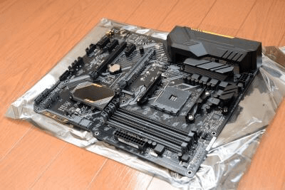
ATX Motherboards are electronic boards that contain the most basic set of devices to configure a system for ATX-specification computers.

Abbreviated as MB, it is also called a system board, mainboard, or logic board. All parts of the computer are connected to the motherboard in some way via cables, connectors, etc., and communication and power supply between various parts are also performed through the motherboard.

The motherboard is the heart of the computer and plays an important role in supporting the basic operation of the computer.

If the connection methods and communication standards are not compatible, the performance of the parts used cannot be fully demonstrated, or in the worst case, the parts themselves cannot be connected, resulting in malfunctions such as not being able to use them.

Uses of ATX Motherboards

ATX Motherboards are used for internal components in desktop PCs and servers in combination with ATX power supplies, CPUs, memory, and external storage devices.

There are standards for motherboard size. The larger the size of the motherboard, the greater the number of ports available, and the more parts can be connected, the more expandable the motherboard.

  • ATX
  • Micro ATX
  • Mini ITX
  • Nano ITX

The main difference is that the smaller the motherboard, the smaller the number of connectable terminals, due to their different sizes.

The smaller size allows the motherboard to be installed in a smaller PC case, so they are mainly used when you want to build a smaller size computer to save space. Also, the smaller the motherboard, the cheaper it is in general, so there is room for consideration when you want to keep the price down.

ATX Motherboards are the largest size standard for motherboards, so they can be installed in middle tower or larger PC cases.

The smaller Micro ATX and Mini ITX motherboards are compatible with smaller PC cases such as mini-towers, and can save space compared to ATX Motherboards.

The required specifications of the motherboard vary depending on the number of parts to be installed, such as connected devices and expansion boards, as well as communication standards, so it is necessary to select a motherboard that meets the requirements.

Principle of ATX Motherboards

ATX Motherboards are integrated circuit boards with patterns transferred onto a printed circuit board, and the board is made of a hard, non-conductive material.

Sockets, terminals, and various slots for connecting other components are mounted on the printed circuit board.

ATX Motherboards contain the following components, depending on the components installed:

1. Chipset

The chipset controls the flow of data from the external interface.

2. CPU Sockets

A component into which the CPU is inserted. When installing the CPU socket, it is necessary to confirm that the chipset matches the CPU standard.

3. Memory Sockets

This is a component into which memory is inserted. There are different memory standards, such as “DDR4,” which mainly affects data transfer/processing speed. Since the shape of the socket differs depending on the memory standard, it is necessary to check whether it meets the corresponding standard.


カテゴリー
category_usa

Black Anodized Aluminum

What Is Black Anodized Aluminum?

黒アルマイト

Black Anodized Aluminum is a type of color anodizing in which the surface of anodized aluminum is colored black with a dye.

Anodized aluminum is aluminum that has undergone anodizing, during which an oxide film forms on the surface through electrolysis on an anode. It is more resistant to corrosion than untreated aluminum.

The luster can be altered through various processing methods before and after anodizing. Different types of anodized aluminum, such as matte black anodized aluminum and glossy black anodized aluminum, are available to match the specific requirements of the product, including function and decorative appearance.

Uses of Black Anodized Aluminum

Black anodized aluminum is known for its high corrosion resistance, wear resistance, hardness, and insulation properties. It is widely used in various products, ranging from household items like lunch boxes, water bottles, and cooking utensils to parts for automobiles, semiconductors, industrial equipment, medical devices, and ship and aircraft interiors.

Glossy black anodized aluminum and matte black anodized aluminum are used for optical products.

Principle of Black Anodized Aluminum

Black Anodized Aluminum is produced in the following steps:

1) Anodizing of the aluminum substrate

2) Dyeing of the anodized aluminum

1. Anodizing

3538_Black-Anodized-Aluminum_黒アルマイト-1.png

Figure 1. Schematic diagram of anodized aluminum

Anodizing is a treatment method in which an anodic oxide film forms on the aluminum surface through electrolysis, with aluminum serving as the anode. The process involves dissolving the surface of the aluminum substrate in an electrolytic solution to create the aluminate layer, resulting in a film consisting of two layers: a nonporous barrier film and a porous film.

The anodized aluminum coating is hard and offers excellent abrasion and corrosion resistance, effectively protecting the underlying aluminum substrate. Unlike plating, where a metal film is deposited on the surface using electrolysis, anodizing utilizes the aluminum substrate itself as the anode and undergoes electrolysis.

2. Anodized Aluminum Staining

3538_Black-Anodized-Aluminum_黒アルマイト-2.png

Figure 2. Staining and sealing treatment for anodized aluminum

As previously mentioned, a porous film layer forms on the anodized aluminum coating. In the production of Black Anodized Aluminum, the material is immersed in a dyeing tank, where black dye is introduced into these cavities. The dye is absorbed by the cells, and once absorbed, the cavities are sealed through a perforation process.

The amount of dye absorbed depends on the thickness of the anodized aluminum oxide film. To achieve a darker color, both the film thickness and dye absorption must be increased. Glossy black anodized aluminum and matte black anodized aluminum undergo pretreatment using chemicals.

Luster black anodized aluminum incorporates gloss into the anodized aluminum substrate, while matte black anodizing removes gloss through a matte finish.

Types of Black Anodized Aluminum

Black Anodized Aluminum can be classified based on film thickness and dye.

1. Film Thickness

The standard thickness of Black Anodized Aluminum is approximately 10 to 30 µm. Film thicknesses thinner than 10 µm result in reduced dye adherence to the surface film, affecting color quality. To achieve a consistent black color, a certain level of film thickness is necessary.

While films thicker than 30 µm can be created, they may not be suitable for physically constrained areas, such as narrow tubes or sharp edges. The film’s performance depends significantly on the material, so film thickness should be considered in conjunction with dye compatibility.

2. Dye

3538_Black-Anodized-Aluminum_黒アルマイト-3.png

Figure 3. Structures of typical chromium complex organic azo dye

Organic chromium complex dyes are typical choices for Black Anodized Aluminum. These dye molecules feature a structure in which an organic ligand bonds with metallic chromium in either a 1:1 or 1:2 ratio.

The use of organic ligands in complexation with chromium enhances resistance to light and heat compared to single-chromium ligands. Given that the pore diameter of the film is several hundred Ångströms (Å), while dye molecules measure approximately several tens of Å, the dye molecules penetrate the film’s pores and become colored through adsorption.

Key organic ligands include aromatic rings such as benzene and naphthalene, often featuring chromogenic properties in the form of substituent groups like nitro and azo groups. Dyes bonded to sulfonic acid, hydroxy, or amino groups have also been developed to enhance solubility in solvents.

In Black Anodized Aluminum, exposure to ultraviolet rays and heat from sunlight can lead to the decomposition of dye molecules, resulting in discoloration and fading. Consequently, UV-resistant dyes have been developed in recent years.

カテゴリー
category_usa

Pressure Washer Trucks

What Are Pressure Washer Trucks?

Pressure Washer Trucks are vehicles equipped with a high-pressure pump and water tank for cleaning by spraying water at high pressure.

They are capable of more powerful cleaning than the household high-pressure washers used for cleaning gardens, etc., and can be used for different purposes by changing the nozzle on the end of the vehicle. By using the nozzle, it is possible to clean narrow places where people cannot enter.

The high pressure jet of water allows for fast and efficient removal of heavy dirt. If the water pressure is too high, it may damage the surface to be washed, and if it is too low, the dirt cannot be removed well.

For water pressure, there are cases where the maximum discharge pressure is indicated and there are cases where the normal discharge pressure is indicated.

Usage of Pressure Washer Trucks

Pressure Washer Trucks are mainly used for cleaning, but they can be used for a wide range of purposes.

  • Cleaning of road gutters
  • Disaster restoration work
  • Sludge collection under piles in civil engineering works
  • Dredging of foundations
  • Cleaning and recovery of landscaping work
  • Dredging of general rivers
  • Cleaning of building rooftops and underground water tanks
  • Recovery of sludge from filtration beds of water and sewage systems
  • Cleaning of complex shaped exterior surfaces, walls of ships and buildings, and interior and exterior surfaces of tanks
  • Cleaning of heat exchanger tubes
  • Paint removal from hard paint and lining coatings
  • Dust suppression during concrete repair
  • Chemical cleaning
  • Circulation cleaning
  • Spray cleaning
    etc.

Principle of Pressure Washer Trucks

The structure of Pressure Washer Trucks can be divided into three main parts: the high-pressure pump, the water tank, and the nozzle.

The high-pressure pump is a positive displacement pump such as a reciprocating pump or plunger pump.

These pumps change the volume by reciprocating the piston and push the liquid from the suction side to the discharge side.

High pressure can be obtained by extruding by changing the volume, and it is also possible to change the discharge amount.

The volume of water that can be used for cleaning depends on the capacity of the water tank, so it is important to pay attention to this when selecting a product.

The nozzle can be replaced depending on the application, and the water pressure can also be adjusted by changing the nozzle diameter.

The tip of the nozzle is designed to smoothly inhale and discharge dirt, thereby increasing work efficiency.

Pressure Washer Trucks use a pump to pressurize the water and a narrower nozzle to increase the water pressure.

Working with Pressure Washer Trucks

High-pressure cleaning is performed at various sites, including exterior wall and site cleaning at construction sites, cleaning of tanks, pits, and piping for maintenance, suction of sludge, and stripping of painted surfaces.

Pressure Washer Trucks are highly mobile and can be moved from site to site, so contractors who undertake cleaning work own several of them, and they are especially deployed at steel mills and large chemical plants.

Pressure Washer Trucks may be dispatched independently, but most of them have a cleaning water tank capacity of about 2 tons, and some of them are equipped with powerful suction capability.

The nozzle operators must be equipped with protective equipment to prevent self-inflicted injuries to their hands and feet, and must control the pressure so as not to damage the objects to be cleaned. If the contaminant is hazardous, care must be taken to prevent it from scattering.

Difference from Home-Use High-Pressure Cleaners

Recently, home-use high-pressure cleaners are sold at home centers. The most powerful type for home use has a capacity of 90 kg/cm2, while some Pressure Washer Trucks have a capacity of 200 kg/cm2. pressure cleaners for commercial use, but they are very heavy even when placed on a cart, making them difficult to maneuver when moving them around the factory premises.

カテゴリー
category_usa

Clean Bench

What Is a Clean Bench?

Clean Benches

A clean bench is an enclosed workbench that maintains a high level of cleanliness to prevent contamination from dust and airborne microorganisms.

Uses of Clean Benches

Clean benches are used for handling microorganisms, cells, and other materials that should not be contaminated by bacteria or relics from the outside.

For example, in the pharmaceutical field, clean benches are used for cultivating microorganisms and cells and preparing pharmaceutical products, while in the industrial field, clean benches are used for manufacturing electronic components such as semiconductors and liquid crystals, which require high precision.

There are two types of air blowing positions: from the front or from the ceiling. When blowing from the front, the air stays around the workers and equipment, and there is a possibility that the cleanliness level will decrease, so aseptic work such as culturing organisms is done by blowing from the ceiling.

Most clean benches are usually enclosed, but there are also clean benches without enclosures, which contribute to improved workability.

Principle of Clean Benches

To prevent dust and airborne microorganisms from mixing in, the inside of clean benches are kept at positive pressure (the pressure inside the bench is higher than the outside air pressure) to block the flow of air from outside to inside, and only air that has been cleaned by a HEPA filter or other high-performance filter with dust removal function is taken into the bench.

In general, the dust collection efficiency exceeds 99%.

The main air filter must be HEPA or ULPA, in addition to having no peeling or rusting of the wall surfaces. In addition, when handling acids, organic, and toxic gases, it is clearly stated that they must have a structure that allows exhaust through a predetermined route and that lighting and germicidal lamps must not be turned on at the same time unless there is an agreement.

HEPA Filter

HEPA stands for High Efficiency Particulate Air Filter.

Although it is an important component for maintaining cleanliness in clean rooms, its performance declines with use due to clogging. The general life is about 3 years, but it depends on the usage environment. It is important to maintain the cleanliness of the clean bench by periodically checking the performance of the filter to see if the air volume is flowing and if there are any cracks or cracks in the filter.

Difference Between Clean Benches, Draft Chamber, and Safety Cabinet

Draft chambers and safety cabinets are similar to clean benches and differ greatly in airflow and purpose of use.

Clean benches are used to prevent dust and other foreign matter from entering the sample, and their primary purpose is to protect the sample. In clean benches, the air inside a container that has become positively pressurized flows out through the window where the work is done, which may expose workers to radiation if they handle hazardous materials.

The primary purpose of a draft chamber is to protect workers because hazardous gases, etc., are treated with a scrubber and discharged out of the system via ducts. On the other hand, it is not suitable for maintaining a clean environment because atmospheric air enters inside the container. After all, the pressure inside the container is negative.

The safety cabinet sends filtered and normalized air into the container while safely exhausting it through an exhaust filter from an intake port separate from the work window. Therefore, safety cabinets can protect samples and workers at the same time and are used when handling viruses or bacteria that pose a biohazard risk.

カテゴリー
category_usa

Cubicle

What Is a Cubicle?

Cubicles
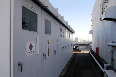
A cubicle is a facility that contains a set of high-voltage power receiving equipment and low-voltage substation equipment.

The voltage of electricity transmitted from a power plant is generally 6,600V, and in most cases, outlets and lighting are powered by 100V or 200V. A cubicle is a metal box containing equipment that steps down the received electricity to the voltage required for the demand facilities.

Generally, a cubicle is installed in facilities that have an electricity supply contract with an electric power company for 50 KW or more.

Uses of Cubicles

Cubicles are installed in all kinds of places, including urban areas and residential areas, such as:

  • Commercial facilities such as shopping malls and supermarkets
  • Public facilities such as community centers and schools
  • Residential facilities such as student dormitories and apartments
  • High-rise office buildings
  • Processing plants and small factories

Principle of Cubicles

Cubicles consist of power receiving equipment, substation equipment, low-voltage equipment, and an enclosure.

1. Power Receiving Equipment

Power receiving equipment is the equipment used to accept high-voltage power distribution. It mainly consists of disconnectors and circuit breakers.

When a short circuit or ground fault occurs due to the failure of substation equipment or high-voltage distribution lines in cubicles, a large current flows to the upper circuits of the power company’s power grid. If this large current is left unattended, the electric power company’s power grid will be cut off for safety, causing a power outage in the surrounding area. This is a spillover accident.

The role of the circuit breaker is to cut off the power supply when it detects an overcurrent or ground fault in the cubicles to prevent a spillover accident. There are two types of circuit breakers in cubicles: PF-S type and CB type.

The PF-S type uses a high-voltage current-limiting fuse (power fuse) and a load break switch, while the CB type uses a circuit breaker and a protective relay, and most of the circuit breakers are vacuum circuit breakers. The PF/S method is inexpensive and used when the power receiving capacity is small, while the CB method is used when the power receiving capacity is large or when the load current is frequently switched.

2. Substation Equipment

Transformers are devices that convert the high voltage received into low voltage.

Oil-filled transformers and molded transformers are used as transformers. The upper limit for storage in cubicles is approximately 750 kVA, and a separate installation is required for capacities higher than 750 kVA.

In addition, the use of substation equipment causes the current to slow phase. When the current is slow-phased, losses occur in power transmission and distribution. For this reason, many power company supply contracts include clauses that increase the power factor when the power factor drops and the power factor delayed by the capacitor is brought closer to 1.

3. Low-Voltage Equipment

Low-voltage equipment is the equipment used to distribute transformed power to various locations. Wiring circuit breakers and ground-fault circuit breakers fall into this category. Depending on the equipment configuration, electromagnetic contactors and electromagnetic switches may be installed inside the cubicles.

4. Enclosure

The enclosure is an outer metal box to protect the internal equipment. Steel plates of 1 to 3 mm in thickness are mainly used. The outer surface is painted milky white or beige to prevent corrosion and to be pleasing to the eye.

Inside the cubicles, there are parts of the cubicles where the charging section is exposed, which can cause an electric shock if touched without protective measures. There is a risk of electric shock if the inside of cubicles in public facilities is easily penetrated. Door opening/closing handles are often equipped with locks.

Substation equipment and distribution lines have the property of generating heat when electricity is used. If the amount of heat generated is large, there is a risk of heat buildup inside the cubicles, resulting in high temperatures.

カテゴリー
category_usa

Carrier Tape

What Is Carrier Tape?

Carrier Tapes
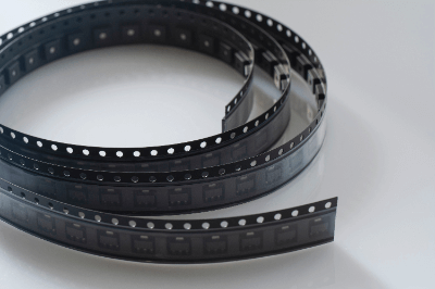
Carrier Tape is a tape used for transporting and storing electronic components, semiconductor semiconductor parts, and microchips.

The main materials used are polystyrene resin and other resin-based materials and paper-based materials.

When handling microchips and other extremely small-sized components, semiconductors can be individually packaged on carrier tape, transported to an assembly plant, and then set on a component assembly machine for transport.

Demand for carrier tape is growing rapidly for packaging ultra-small chip-sized components due to the widespread use of mobile terminals and personal computers.

Uses of Carrier Tape

Carrier tape is used to package extremely small chip size components, which are rapidly growing in demand due to the proliferation of mobile terminals and PCs.

Paper products or embossed products are used depending on the size and application of the component to be packaged.

Examples of ultra-small chip size components include integrated circuits (IC), chip resistors, capacitors, coils, transformers, switches, connectors, relays, quartz crystals, LEDs, transistors, and diodes.

Principle of Carrier Tape

Carrier tape can be used to package minute components by changing the pocket shape to match the component.

Vacuum rotary forming enables sharp pocket forming with a small opening R and retention of firm vertical walls. In addition, it is formed with high precision to ensure that inserted parts do not roll around in the pocket.

Ribbed carrier tape provides ribs in the pockets to restrain component movement and prevent lead breakthrough. Also, to prevent device adsorption, a step is provided at the bottom of the pocket to float the device.

Transparent conductive carrier tape has excellent visibility, conductivity, and heat resistance. Being carbon-free, it is a clean product with low dust emission.

In recent years, environmental considerations have led to the development of environmentally friendly products such as recyclable carrier tapes and carrier tapes made from biomass plastics.

Carrier tape may be wound in reel form when packaging components. This is called a carrier tape reel.

Carrier tape reels are used to feed mounters, which are automated parts assembly machines. Carrier tape wound on a reel is an essential part of an automated assembly line because it can supply parts at high speed.

How to Select Carrier Tape

Depending on the size and application of the component, it is necessary to use either a paper product or an embossed product for carrier tape.

The following explains more specific selection methods:

1. Pocket Depth

The depth of the pocket used for carrier tape should be selected according to the height of the component. If the component protrudes higher than the pocket, it may be damaged during transportation. Conversely, if the pocket is too deep, the part will sway and may be damaged during transport. Selecting the proper depth will ensure safe transport of the parts.

2. Pocket Shape

It is important to select a pocket shape that matches the shape of the part. Ensuring that the part is held securely in the pocket will help protect the part from vibration and shock during transport. Also, depending on the shape of the pocket, it may be easier to remove the parts and set them on the mounter, leading to more efficient assembly work. 

3. Conductivity

Some carrier tapes are required to be conductive. When carrier tape is charged, it attracts dust and dirt. For semiconductor components, dust and dirt can lead to performance degradation. Also, if static electricity builds up on the carrier tape and causes dielectric breakdown, an abnormal current will flow through the IC device, causing the component to fail. When inserting such components that are greatly affected by dust and static electricity, it is necessary to select a conductive carrier tape. 

4. Dust Generation

Some carrier tapes must have low dust generation. For example, for precision components such as semiconductor parts and microchips, it is essential that there be no dust generation. If dust is generated, it will adversely affect the function of the component. For this reason, non-carbon transparent conductive carrier tapes, etc. are used.

カテゴリー
category_usa

Capture Card

What Is a Capture Card?

Capture CardsA Capture Card is a device used to capture video and audio from AV equipment such as TVs, DVD players, and game consoles.

By connecting the AV equipment to a PC, the video and audio being played back on the AV equipment can be imported to the PC. The captured video and audio are stored on the hard disk of the PC and can be used for editing and distribution.

Some capture cards offer pass-through output to minimize latency during gameplay. Capture Cards are in high demand these days as streaming is becoming more common.

Applications of Capture Card 

Capture Cards are devices that digitize video and audio signals to enable viewing and editing of various media on a PC. Capture Cards are primarily used for the following applications:

1. Game Recording

Games can be recorded as they are being played, played back later, edited, and posted to YouTube or other sites. It can also record the audio of the game being played. 

2. Video Streaming

Capture Cards can be used to capture and distribute videos of TV shows and movies. You can also distribute videos you have created yourself.

3. Video Editing

Capture Cards can be used to capture and edit video from TV programs, movies, etc. on your computer. The edited video can be written and saved on DVD or Blu-ray.

4. Security Camera

Capture Cards can be used to capture video from security cameras for viewing on a PC. The recorded images can also be submitted as evidence if necessary.

5.Capture Card Principle

Capture Cards receive video and audio signals from a game console or camera as an input source. This signal is sent through a connecting cable such as HDMI or component. Next, a chip inside the capture card converts this analog or digital signal into digital data.

The converted digital data is then transferred to the computer via an interface such as USB or PCI Express. During data transfer, compression algorithms are used to ensure that video and audio quality is not compromised.

The most common compression formats are H.264 and H.265. These compression technologies can significantly reduce data volume while maintaining high quality.

Types of Capture Cards

There are two main types of Capture Cards: external and internal.

1. Classification by Installation Method

External type
External types are equipped with interfaces such as USB, Thunderbolt, and Wi-Fi, and can be connected to a PC. They are compact, lightweight, and easy to carry, making them suitable for shooting and recording on the go. They can also be shared by multiple PCs.

Built-in type
The built-in type can be used by attaching it to the main body of a PC. Since it is directly connected to the PC, it enables fast and stable video capturing and is suitable for capturing high quality images. Some types are equipped with multiple input terminals, making it possible to capture video and audio from multiple AV devices. 

2.Classification by Signal Acquisition Method

Analog type
Analog types can capture analog signals such as composite and S-Terminals. It can process video and audio from old TVs and camcorders.

Digital type
Digital type can take in digital signals such as HDMI, DVI, and DisplayPort. The digital type can import video and audio from SLR cameras and the latest game consoles, and edit and process them digitally.

Multifunctional type
Multifunctional types not only capture video and audio, but also support video editing and distribution. In many cases, software is included to enable simple editing and streaming.

カテゴリー
category_usa

Galvanostat

What Is a Galvanostat?

A galvanostat is a device in electrochemistry.

This device applies a voltage to a sample to induce a chemical reaction or to detect a change in a physical quantity caused by a chemical reaction. Galvanostats are commonly used in combination with potentiostats, which are also measuring devices in electrochemistry.

These two devices control a cell containing three types of electrodes: a sample electrode, a counter electrode, and a reference electrode. What is controlled by potentiostats and Galvanostats is different, with the former controlling voltage and the latter controlling current.

Applications of Galvanostats

Galvanostats are used in chronopotentiometry and battery discharge testing.

1. Chronopotentiometry

Chronopotentiometry is a method of measuring data by tracking changes in electric potential over time. Generally, a constant current is applied to the sample electrode and parameters related to electrochemical reactions are obtained with no flow between the sample electrode and the electrolyte.

The parameters obtained include the concentration of substances involved in the redox reaction and the diffusion coefficient. To handle the redox reaction of the components present in the electrolyte, platinum is used as the electrode for this measurement, as it does not easily dissolve into ions.

2. Battery Discharge

There are primary and secondary batteries. Primary batteries are used-up batteries and can only be discharged. Secondary batteries, on the other hand, can be discharged and recharged, and can be used repeatedly.

Galvanostats are used to evaluate discharge and recharge performance. Lithium-ion batteries are examples of rechargeable batteries. Lithium-ion batteries are used in smartphones and hybrid vehicles.

Principle of Galvanostat

Galvanostat requires a signal generator and a PC as well as the object to be measured. A frequency response analyzer (FRA) is used for the signal generator, which adds a sine curve with a constant frequency. The sine curve output from the FRA is input to the Galvanostat to produce a voltage. The voltage generated in the Galvanostat causes a current to flow through the object being measured, and the response signal from the sample is input to the Galvanostat.

The signal input to the Galvanostat is converted to a wave and input to the FRA. At this time, a sin (omega) wave is generated, whose phase is shifted by omega from the input sin wave. The phase shift depends on the object to be measured.

The sin (omega) wave is Fourier transformed in the FRA and only the components of the measurement frequency are extracted. Finally, the data extracted by the Fourier transform is sent to a PC. By monitoring these values, it is possible to quantitatively evaluate the parameters.

Other Information About Galvanostat

1. Principle of FRA

FRA is a device that applies a sinusoidal signal to an object under test and observes its frequency response. FRA uses a digital correlation method called SSC (Single Sine Correlation) to determine the impedance.

FRA is the most widely used measurement method for electrochemical measurement applications, with a basic amplitude accuracy of 0.1% and a basic phase accuracy of 0.1 degree. The response signal returned from the object to be measured is not only the frequency of the input signal, but also includes other frequency components.

In order to obtain only the frequency of the input signal, FRA multiplies the response signal by a sin wave in phase with the input signal and a sine wave with a phase shifted by 90 degrees. By dividing the frequency components into real and imaginary components, it is possible to acquire the same frequency components as the input signal in the response signal.

2. Features of FRA

One of the features of FRA is its excellent noise reduction function: FRA can reduce high-frequency components to -60dB or lower with a single measurement using the single sine correlation method. Further removal of noise components is possible by increasing the number of integrations. Even if the signal to be analyzed has an amplitude below the noise, it can still be extracted.

Another advantage is the wide frequency range (10uHz to 1MHz) over which it can measure. Since the signal is digitally processed including the output of the internal oscillator, there is no waveform distortion.

Heat Shielding Sheet

What Is Heat Shielding Sheet ?

Heat shielding sheets are made by processing chemical materials and are heat-resistant materials with excellent noncombustibility properties that prevent the temperature of objects and spaces from rising by inhibiting heat transfer. Materials include metal, glass, silica, rubber, and plastic.

Heat shielding sheets undergo a heat-induced change of state depending on the sheet material.

Polypropylene (PP), for example, is a solid and easily deformable sheet in the low temperature range.

However, when the temperature range reaches medium, it begins to deform, becoming rubbery, intermediate between a solid and liquid state, and showing elasticity. Under high temperatures, it melts and becomes a sludgy liquid state and begins to flow.

In general, heat-resistant sheets undergo a state change when exposed to heat, losing their functionality as described above.

Uses of Heat Shielding Sheet

Heat shielding sheets are used not only to withstand external temperature changes in products, but also to prevent the temperature of objects from rising or falling. Heat shielding sheets are mainly used in industry, construction, and the food industry, but heat-resistant sheets can also be used in general life outside of industrial applications.

1. General Use

In general life, one example is the use of heat shielding sheets as heat-resistant and heat-insulating material from floor heating. Underfloor heating can be efficiently heated by placing an insulating sheet under the floor heating system. However, while blocking cold air from under the floor, it must also withstand heat from the floor heating. Therefore, laying heat shielding sheets can solve these problems.

2. Industrial Applications

In industrial applications, heat shielding sheets have different uses depending on the temperature zone they can withstand. For example, at minus 50°C or lower, products using silicon or glass as materials are used, which are utilized at construction sites and for material transportation. In addition, at temperatures of approximately 200°C, they are used to prevent sparks and spatter in welding operations.

Heat shielding sheets will have different heat resistance test results for the same product, depending on the nature of the material and the environment in which it is used. Therefore, it is important to test the performance of a product in a real environment before using it.

カテゴリー
category_usa

Galvanometer Scanner

What Is a Galvanometer Scanner?

A galvanometer scanner is a method for scanning lasers and other devices.

An optical element (mirror or lens) mounted on a rotating shaft is rotated at high speed by an electromagnetic motor, etc. Based on the output from the position sensor, a servo driver controls the motor at high speed and with high precision to achieve the scanning function.

By using two galvanometer scanners, one for X and the other for Y, laser scanning can be performed in a two-dimensional flat plane. There is also a 3D galvanometer scanner that can scan in three dimensions by adding a galvanometer scanner in the Z direction.

Uses of Galvanometer Scanners

They are used for high-speed, high-precision laser drilling, laser marking, welding, and other processing, as well as laser scanning for 3D printers using trendy photo-curable resins. It is used for parts processing that requires micron-level accuracy.

They are also used in optical coherence tomography (OCT), which visualizes the internal structure of minute tissues by taking advantage of its features that can be controlled even on a nanometer scale, for high-precision, high-speed, and wide-area scanning.

Principle of Galvanometer Scanners

Galvanometer scanners are characterized by good scanning accuracy, high speed capability, high resolution, easy operation, and excellent cost performance. They are used in many applications such as laser scanning because they can operate at high speed for long periods and maintain high repetitive positioning accuracy even when the temperature changes.

The mirror size (inertia) determines the galvanometer scanner’s configuration. Since the scanner is selected to suit the inertia, it may not work well when replaced with a mirror of a different weight or center of gravity.

Selecting a galvanometer scanner is based on the scanning method (step, raster, or vector scanning), required speed, and accuracy as well as mirror size. care must be taken when selecting galvanometer scanners.

Mirrors are available in a variety of coatings depending on the wavelength of the laser or other device used.