カテゴリー
category_usa

Wet Film Thickness Gauges

What Is Wet Film Thickness Gauges?

Wet Film Thickness Gauges

Wet Film Thickness Gauges are devices that measure the thickness of a wetted surface on an object.

Most of the wet film thickness gauges are analog type film thickness gauges, and the film thickness gauge is actually applied to the wet surface, and the thickness of the film is measured by visually confirming how wet the film thickness gauge is. It is a destructive inspection because the film thickness gauge is actually brought into contact with the wet surface.

Products that measure wet thickness digitally are also on sale. It can be classified into comb type and roller type. The film thickness can be obtained quickly because it is a manual reading type.

Applications of Wet Film Thickness Gauges

Wet Film Thickness Gauges are used in automotive and other painting processes, food factories, and laboratories.

Examples of specific uses include controlling paint thickness in the painting process, controlling the amount of paint applied in the food manufacturing process, and measuring wetting.

When selecting Wet Film Thickness Gauges, it is necessary to consider the accuracy of the film thickness measurement, the ease of reading, and the size of the amount to be destroyed. There are cheap disposable materials and types that can be washed and used, so you can choose according to the type of liquid you use.

Principles of Wet Film Thickness Gauges

  • Comb Type
    Wet Film Thickness Gauges have a comb-shaped groove of different heights, equally spaced. When the comb is pressed against the film to be measured, liquid penetrates the grooves. The thickness of the film can be measured by taking a reading from the area where the liquid has not penetrated. The range of film thickness measurement depends on the distance between the groove heights. Inexpensive and disposable, many of these products are suitable for measuring film thickness in cases where cleaning is not easy or chemicals are hazardous to touch directly.
  • Roller Type
    The roller type has a groove in the center of the roller in the centrifugal direction and its grooves are of different heights. The feature of this type is that the part that destroys the liquid is less than that of the comb type.
カテゴリー
category_usa

Wedge Prisms

What Are Wedge Prisms?

Wedge prisms are triangular prisms made of transparent material. Glass or plastic is used as the material. When parallel or laser beams are projected onto a prism, they are reflected or refracted.

Wedge Prisms, also known as Risley Prisms, are prisms with inclined optical surfaces.

Light entering wedge prisms is refracted toward the thicker side and is used to refract light at a special angle.

Uses of Wedge Prisms

Wedge Prisms are used to deflect light at minute angles. Declination is the angle created by the incident and emitted rays of light when they are refracted by a prism, and it depends on the apex angle of the prism (the angle facing the base of the triangle) and the refractive index.

It can be used for beam steering, either alone or in combination with other Wedge Prisms. Beam steering components are an integral part of many laser-equipped optical systems, including endoscopic laser scalpels.

Principles of Wedge Prisms

Wedge Prisms are prisms with one side inclined at a very small angle to the other side. Light entering Wedge Prisms is refracted in the direction of the prism’s thickness, which allows the light to be refracted at a special angle. This depends on the angle of the exit facet and typically deflects a beam incident on a perpendicular facet to an angle of 2° to 10°.

Rotating the wedge prisms with the laser as the source causes the trajectory to form a circle; using two wedge prisms, the light beam can be freely rotated and oriented in any direction relative to the incoming beam. It is also possible to double the amount of declination.

In addition, two Wedge Prisms can be used in combination to function as an anamorphic prism. Anamorphic prisms are used to convert an elliptical semiconductor laser beam into a nearly circular beam by changing the vertical and horizontal image magnification. Conversely, it is also possible to transform a circular beam into an elliptical beam.

カテゴリー
category_usa

Inside Vernier Calipers

What Are Inside Vernier Calipers?

Inside Vernier Calipers are calipers specially designed to measure inside diameters. They are used in the same way as regular calipers, but they do not have a function for measuring external dimensions.

Analog calipers are read using a vernier scale, while digital calipers are the same as regular calipers in that the numerical value is directly displayed.

The feature of these calipers is that the jaws for measuring the inside diameter are longer, allowing the jaws to be inserted deeper into holes and tubes. Some manufacturers offer groove and point calipers that can measure stepped inside diameters and narrow grooves.

Uses of Inside Vernier Calipers

Inside Vernier Calipers are used to measure the inside diameter of holes and pipes.

Since the starting base point for measurement is not zero, it is necessary to create a base point using an inside width or ring gauge combined with a block gauge. position. Some digital Inside Vernier Calipers have an offset function, which allows the encoders base point to be adjusted freely, so the starting position can be set as desired.

Principle of Inside Vernier Calipers

The principle of Inside Vernier Calipers is similar to that of calipers for measuring inside diameters. As with ordinary calipers, the analog type reads the position where the main scale and the vernier scale coincide as a decimal point, while the digital type directly displays the numerical value of the scale attached to the main scale by means of an encoder.

Since measurement is often made by placing the jaw on the arc portion, it is necessary to pay attention to the pitching and yawing inclination of the scale. Tilting of the caliper or jaw can cause errors.

It should also be noted that calipers are not measuring instruments that follow the Abbe’s principle, so if the measuring pressure is too strong, the jaws will open in a “C” shape, making it impossible to read the correct value.

When measuring a wall with a small radius of curvature, the corner of the jaw will hit the inner wall and the tip will be separated from the inner wall, which may cause an error. If this kind of phenomenon occurs, the inside caliper cannot solve the problem, so another measuring device will be used.

カテゴリー
category_usa

Contour Machine

What Is a Contour Machine?

Contour Machines
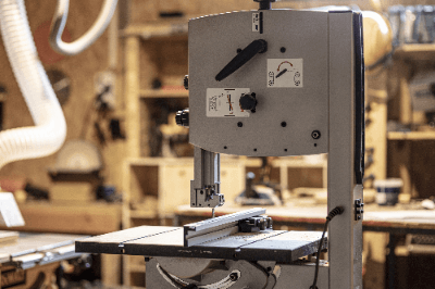
A contour machine is a machine tool for cutting sheet metal and steel.

Also called a band saw, as the name implies, it can cut sheet metal and steel by rotating a band saw (a metal wheel with a saw blade).

The sheet metal or steel material is prescribed, and the workpiece is moved along the line and pressed against it as it is processed. A relatively small contour machine can process not only straight lines but also any desired shape, such as a rounded edge. Larger machines are designed to cut thicker steel materials, so they do not allow as much freedom in the cutting process.

Uses of Contour Machines

Contour machines are used for cutting and processing metal materials. Here are some examples of use.

  • Cutting long steel materials to a specified size for welding.
  • Roughing materials before finishing them on a milling machine.
  • To cut sheet metal into desired shapes quickly.

It is installed in many places where metal materials are handled daily, such as sheet metal, molds, and ironworking shops.

Roughing with contour machines reduces the amount of time and effort required for finishing work. Some large contour machines can be set up and operated by simply pushing a button, and the machine does not need to be operated until cutting is completed.

So, by using good contour machines, workability can be improved. In addition to large, installed machines, there are also small, portable types that can be brought to construction sites, and they are used in a variety of locations.

Features of Contour Machines

This section describes the types and features of contour machines (band saws).

  • Tabletop horizontal type
  • Tabletop vertical type
  • Installation type
  • Portable type

The tabletop horizontal type is relatively small and can be carried around.

The horizontal tabletop type is relatively small and portable. They are used for cutting metal pipes, plates, L-shaped angles, H steel, etc. at construction sites. However, it is not possible to cut any shape at will. It is possible to cut in straight lines and at set angles.

The tabletop vertical type is used for cutting relatively soft materials such as wood and aluminum. Since the workpiece is pressed against the blade for cutting, it can be cut into any desired shape.

The installation type is mainly used in manufacturing and other places where metal materials are handled. There are two types of installed types, horizontal and vertical, and it is necessary to select the type to use depending on whether you want to cut large steel materials or sheet metal, or relatively thin steel materials automatically, into desired shapes.

The portable type is useful for materials that need to be cut on the spot or in high places. They are generally rechargeable, cordless, and stress-free. However, the blade must be applied at a certain angle or the band saw may break. While the flexibility is high, the frequency of band saw breakage tends to be higher than with other types.

カテゴリー
category_usa

Connector Terminal

What Is a Connector Terminal?

Connector Terminals
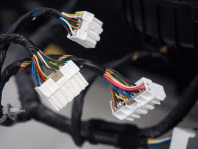
A connector terminal is a component that connects electronic circuit boards, electronic components, and electronic wiring in a way that allows easy connection and disconnection.

There are male and female connectors, and when they are connected, they are energized. Since there are pairs of male and female connectors, each with its specialized combination, connecting the wrong one can cause poor contact. Insert contacts with wires crimped to the connector terminal and secure them in place.

Installation and removal of connector terminal depend on the lock shape at the time of connector mating and varies depending on the application, from those that can be easily detached to those that cannot be easily removed.

Uses of Connector Terminals

Connector terminals are used in many situations for communication and power supply between devices because they can be detached and can protect and insulate contacts.

The use of connector terminals improves the maintainability and convenience of equipment and the reliability of connection points. They are used in devices with electronic circuit boards and electronic components and have a wide range of applications.

1. Automobiles

Connections for electronic components and electronic wiring, connections between electronic circuit boards and electronic boards used in ECUs, etc. High-current connections for electric vehicles, and high-speed transmission connections for sensors such as cameras for automatic driving.

2. Smartphones

Connector terminals are used for connections between electronic circuit boards, USB connections, etc.

3. Industrial Equipment

Connector terminals are used for highly reliable power supply connections, high-current connections for solar panels, high-speed transmission connections for communications, etc.

Principle of Connector Terminals

Connector terminals are provided in pairs, male and female, and can be easily connected and disconnected electrically by removing and installing the connector terminals.

Connector terminals are mainly used for:

  • Contacts to energize
  • An insulator to hold the contact
  • A shell to protect the insulator

The above three components make up a connector terminal.

1. Contact

Contacts are metal conductor parts that conduct current and transmit electrical signals. As with connector terminals, there is a pair of male and female contacts, and connecting the wrong one can cause poor contact.

Although contacts can conduct electricity, even if they are touching each other, depending on the grounding area, etc., electrical resistance may increase and transmission loss may increase, resulting in low reliability. For this reason, the mating surfaces of male and female contacts are designed to have moderate mating dimensions that can be removed and attached using the springiness of the metal, and a certain contact pressure is applied.

2. Insulator

Insulators are mainly composed of insulating resin and have the functions of holding contacts in a certain position and insulating and protecting contacts from the outside. There is a wide range of insulators, from those that can hold numerous contacts, to those with levers that cannot be easily removed, to those with rubber or other material on the mating surface of the male and female contacts to provide waterproof performance.

3. Shell

Shells are metal parts that generally protect insulators, and are mainly used when they are fixed to the sides or back of equipment or when electrical noise suppression is required. There are a wide variety of shells, including metal, plastic, and waterproof ones, and they should be selected according to the application.

Other Information on Connector Terminals

Types of Connector Terminals

There are four major types of connector terminals based on the connection method.

  • Connection of electronic circuit boards to electronic wiring: Board to Wire (B to W)
  • Connection of electronic circuit board to electronic circuit board: Board to Board (B to B)
  • Connection of electronic devices to electronic devices: INPUT / OUTPUT (I / O)
  • Connection of electronic circuit boards to electronic components: short-circuit connectors, IC sockets, etc.

1. Connection of Electronic Circuit Boards and Electronic Wiring
Connect electronic circuit boards and wires via connector terminals. Since wires can be freely routed according to their length, they are most commonly used for their ease of use.

2. Connection of Electronic Circuit Boards to Electronic Circuit Boards
Electronic circuit boards are directly connected with connector terminals. Since no wires are involved, electrical resistance is low and signal transmission efficiency is high.

3. Connection of Electronic Devices to Electronic Devices
Electronic devices are connected to electronic devices via connector terminals and wires. This is mainly used to exchange signals between devices.

4. Connection Between Electronic Circuit Boards and Electronic Components
Connections are used on electronic circuit boards, where connector terminals are used as sockets for shorting circuits or plugging in ICs or relays.

カテゴリー
category_usa

Coil Tube

What Is a Coil Tube?

A Coil Tube is a special type of tubing with a unique helical shape and design.

Coil Tubes are flexible to bending and twisting, but also have a certain rigidity. This makes many types of Coil Tubing suitable for a variety of applications.

Uses of Coil Tube

1. Heat Exchangers

Coil Tubes are used in heat exchangers to efficiently transfer heat from liquids and gases. The helical structure allows long tubes to fit into compact spaces, saving space.

They are widely used in refrigerators, freezers, air conditioning systems, and other cooling devices.

2. Cooling Equipment

Coil Tubes are used in components such as condensers and evaporators, which absorb or dissipate heat to produce a cooling effect. They play an important role in a wide range of cooling equipment, from household appliances to industrial refrigeration systems.

3. Heating Devices

Heating Coil Tubes are used to heat objects through steam or heating media. Utilized as heating elements in industrial processes and household appliances, they are widely used in manufacturing, food processing, medical equipment, and many other fields.

4. Medical Equipment

Coil Tube is applied to medical devices such as endoscopes and catheters. Coil Tube, with its flexibility and rigidity, is important for smooth and safe medical procedures such as surgery and diagnosis.

5. Automotive Industry

In the automotive industry, Coil Tube is also used in components such as brake systems and fuel supply systems, contributing to improved automobile performance.

Principle of Coil Tube

1. Uniform Heat Exchange

Coil Tubes are helically wound, which increases their surface area. This characteristic allows liquids and gases to come into contact with more surfaces as they pass through the Coil Tube.

As a result, even heat exchange is possible. For example, when Coil Tube is used in a heat exchanger, efficient heat transfer takes place.

2. Both Rigidity and Flexibility

Coil Tubes combine a certain degree of rigidity and flexibility due to their helical structure. Because the tube is helically wound, it exhibits a certain resistance to bending and twisting, but at the same time it is flexible enough to be bent.

This property allows Coil Tube to be used in a wide variety of applications, especially in tight spaces and complex geometries. 

3. Strength and Durability

Coil Tubes are subjected to the pressure of liquids and gases inside, so a certain level of strength and durability is required. Coil Tubes are manufactured with the appropriate strength and durability by designing the materials and structure.

Especially in the industrial field, high quality and reliability are required because they are used in harsh environments.

Types of Coil Tubes

1. Coil Tube for Cooling

Coil Tubes for cooling are tubes that absorb heat and cool by passing refrigerant or cooling liquid inside. They are used in a wide range of applications from household appliances such as refrigerators, air conditioners, and freezers to industrial refrigeration equipment. These Coil Tubes have high thermal conductivity and durability and provide efficient cooling.

2. Coiled Tubes for Heating

Coil Tubes for heating are tubes used to apply heat by passing steam or heating medium inside. They are used in furnaces, steam generators, boilers, and play an important role in various industrial processes. Coil Tubes for heating require high heat resistance and stable operation at high temperatures.

3. Coiled Tubes for Heat Exchange

A heat exchange Coil Tube is a tube used to exchange heat between two fluids. Heat is transferred between the fluid flowing through the inner Coil Tube and another fluid flowing on the outer Coil surface, thereby cooling, heating, or regulating temperature. They are used in heat exchangers, distillation equipment, solar water heaters, etc.

4. Linear Coil Tube

Linear Coil Tubes are coils wound in a straight line, with a large bending radius and long tubes. This type of Coil Tube is used especially when long lengths of tubing are required or to obtain a shape to suit a particular installation. It is suitable for heat exchange in industrial pipelines and long equipment.

5. Helical Coil Tubing

Helical coil tubing is a helical coil with a relatively small bending radius, allowing for compact designs. It is suitable for heat exchange and cooling in limited space. Helical coil tubing is especially useful in situations where compactness of equipment and devices is required.

カテゴリー
category_usa

Cable Harness

What Is a Cable Harness?

Cable Harnesses
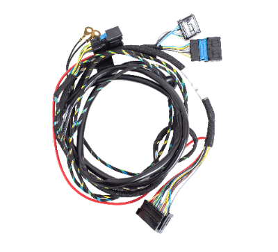
A cable harness is a bundle of multiple wires used for power supply and signal communication, with connectors attached to the ends.

A cable is a multi-core wire. The main use of cables is to transfer information between electronic devices in factory automation, automotive, and other applications.

In some cases, the company prepares its cables for its products, while in other cases, the company makes its cables by making its arrangements through websites where general-purpose parts are available. Because of the wide variety of products and the fact that they are not suitable for automated production, most are produced manually.

Uses of Cable Harnesses

Cable harnesses are used for communication between electronic devices in factory automation (FA), connected autonomous vehicles (xEV), and connected autonomous shared service electrics (CASE).

In the field of consumer electronics, it is used to exchange electrical signals and supply power to home appliances such as air conditioners, refrigerators, and microwave ovens. Harnesses used in audio-visual equipment such as TVs and music players, and office equipment such as PCs and copy machines are often simpler and shorter in structure than those used in automobiles.

In medical equipment, cable harnesses are used in small to medium-sized devices such as blood pressure monitors, electrocardiographs, and angiography equipment, as well as in large devices such as MRI, CT, X-ray equipment, and ultrasound diagnostic equipment. Cable harnesses from many industries are used in production facilities that manufacture automobiles and medical equipment. They are also used to control robots introduced in factory automation.

Principle of Cable Harnesses

Cable harnesses serve to transmit electric power to power various devices and electrical signals for device control, and are incorporated into automobiles and various machinery and equipment.

There are many communication methods used in industrial applications, with CAN, Ethernet, and CC-LINK communications being the most common. In consumer applications, dedicated connectors and USB connectors are used for cables for data transmission and network communication to exchange data, such as audio, video, and data files.

Cables used in cable harnesses consist of multiple wires covered with a sheath. The sheath is used as a protective material for the wires. Especially for wiring to moving control equipment, flexible cables with excellent bending resistance are used only for the moving parts to prevent premature wire breakage.

Other Information on Cable Harnesses

1. Advantages of Cable Harnesses

When wiring becomes complicated, cables may interfere with other wires or parts or may be worn out due to shaking or vibration. Therefore, harnessing cables together protects them.

Another advantage is that some cables can have environmental resistance to fire, oil, noise, etc. as a function. Furthermore, there are other advantages, such as simplified installation and prevention of mistakes through simplification by having the cables grouped.

2. The Future of Cable Harnesses

The cable harness has evolved, especially in automobiles. As more functions are added to automobiles, cable harnesses are being used to connect each device and component, and the number of harnesses is on the rise. Some harnesses have more than 2,000 cables per car, and the total length is said to be as long as 1,000 to 1,300 feet.

In the future, there are many issues to be tackled, such as changes in materials and weight reduction. Not only copper, which has been the mainstream material for cable harnesses in the past but also aluminum is becoming increasingly popular. Furthermore, the demand for cable harnesses is increasing together with the growing demand for electric and hybrid vehicles.

At the same time, changes in consumer behavior are occurring, and the needs for automobile functions are expected to diversify. Cable harnesses are also an important automotive component and must change with these changes in demand and the evolution of technology.

カテゴリー
category_usa

Cable Connector

What Is a Cable Connector?

A cable connector is a connector used to connect communication cables for communication between electrical and electronic equipment and production facilities. A cable connector has different specifications for each communication method, so it is important to select the right cable connector for each purpose and application.

Cable Connectors in Industrial Applications

The main use of cable connectors in industrial applications is to connect large pieces of equipment. Specifically, they are used for machine-to-machine interlock communication during the installation of production equipment, communication between electronic devices in the manufacture of electrical and electronic equipment, and the exchange of control signals for communication.

Cable connectors can be broadly classified into types that correspond to standards according to communication specifications, and it is necessary to select the type of connector that best suits the purpose and conditions of use. There is a wide range of communication methods used in industrial applications, with CAN, Ethernet, and CC-LINK communication methods being the most common.

For example, cable connectors compatible with CC-LINK communication are used to connect cables that communicate via CC-LINK communication for monitoring production equipment in different buildings. Connectors compatible with CAN communication are used as CAN communication between the battery management system and the battery itself through RS-485 communication, etc.

Cable Connectors in Consumer Applications

Cable connectors are also used in consumer applications for exchanging data between individuals or corporations. Consumer applications can be broadly classified into the following two categories.

1. Cable Connectors for Receiving and Transmitting Data

Cable connectors are used to exchange data, such as audio, video, and data files. In the past, there were many connectors dedicated to mice and keyboards, but now USB type connectors are increasing.

The USB type is the most recognizable cable connector commonly used in daily life for exchanging data files and supplying power to peripheral devices. Type A USB used to be the most common type, but recently the use of Type C is increasing.

2. Cable Connector for Network Communication

Cable connectors for network communication, such as ethernet cables, are common. This is used for internal data transfer among PCs, displays, and peripherals, and MIDI cables and HDMI cables are often used.

It is also used inside devices such as internal drives, motherboards, and power supplies, and includes Serial ATA and IDE cables.

Types of Cable Connectors

Cable connectors are evaluated according to communication specifications, and each manufacturer produces and manufactures cable connectors in accordance with these standards. However, since many cable connectors look similar, it is necessary to confirm the model number, etc., before purchasing.

It is necessary to select cable connectors while checking the specifications of the equipment you wish to use. Four typical cable connectors are introduced below.

1. D-Type Connector

These connectors are used to pass power information, control signals, etc. between equipment and devices.

2. Can Communication Connector

CAN (controller area network) was developed primarily to build a control network between electrical and electronic devices in vehicles, and these connectors are used for communication.

The automotive industry is undergoing a period of transformation from manufacturer to mobility service provider as it becomes more and more CASE-compliant. Therefore, cable connectors for CAN communication used in automobiles are also evolving to support future services as a provider.

The details of the handshake confirmation using the cable connectors are set for each communication standard, and the data acquired through the cable connectors are processed by a high-level controller.

3. One-Touch Connector

Connectors are sometimes used to connect wiring to electronic components or substrates. Among them, one-touch connectors have a structure with multiple through holes in the body and conductive parts electrically connected in these through holes.

Cable conductors are inserted into the through-holes, and the conductive parts are connected to connect the cables arranged in the multiple through-holes electrically.

As a mechanism for connecting these conductive sections, a lever is provided to lower the conductive section, and the electrical connection is often made by simply lowering the lever.

4. Waterproof Connector

Since the main application of cable connectors is to connect electronic components, it is dangerous for them to get wet and must be avoided. For this reason, some connectors are called waterproof connectors to suit situations where waterproof elements are required, such as outdoor lighting, electrical wiring, and ships.

The general structure is where the connector part is placed in one of the paired waterproof caps, a connector part storage hole in the other waterproof cap, and a terminal is connected to the connector part at the end of the storage hole.

Waterproofing is secured by providing a screw portion in the mating portion of the waterproof cap and mating it, or by sealing it with a sealing material, etc. The degree of waterproofing varies depending on the product, so the product is selected according to how much waterproofing is provided.

カテゴリー
category_usa

Kelvin Probe

What Is a Kelvin Probe?

A Kelvin Probe is a technique for measuring work function and is one of the measurement methods of microscopy.

A metal probe is placed close to the sample surface and the contact potential difference resulting from the difference in work function between the sample and the probe is measured. By using a probe with a known work function, it is possible to determine the work function of the sample surface.

Applications of Kelvin Probe

1. Work Function of Thin Films

The work function of a sample surface varies depending on the quality of the thin film and the presence of impurities. In solar cells and sensors, thin film quality and higher-order structure can affect device characteristics.

By measuring thin films deposited under various conditions using the Kelvin Probe method, it is possible to analyze the correlation between film structure and properties.

2. Solar Cells and EL Devices

Kelvin Probe measurements are often used for metallic and semiconductor materials. Kelvin Probe measurements are used in silicon solar cells, organic thin film solar cells, organic EL, and electrode surface analysis.

The Kelvin Probe makes it possible to map the work function of the surface, which is then analyzed in conjunction with images of the surface measured with a microscope

3. Identifying the Location of Metal Corrosion

Mapping the work function using the Kelvin Probe method also makes it possible to identify corroded areas of metals. Since the work function changes at locations where chemical changes such as corrosion have occurred, it is possible to map where unexpected reactions have occurred in the sample.

Principle of Kelvin Probe

Kelvin Probe is a measurement technique based on Atomic Force Microscopy (AFM) and has a spatial resolution on the order of micrometers. Kelvin Probe is a technique in which a metal probe is brought into contact with the sample surface.

When the probe contacts the sample surface, electron transfer occurs and the Fermi level changes, resulting in a change in the potential of the sample surface. Since the amount of this potential change depends on the work function of the probe and the sample, the work function of the sample surface can be determined by using a probe with a known work function.

By bringing the probe into contact with the entire sample, it is possible to map the work function within the thin film, and the change in work function can be used to identify areas where corrosion or film quality changes are occurring.

Other Information About Kelvin Probe

1. Measurable Materials

The Kelvin Probe method allows non-destructive measurement of samples. Both organic and inorganic thin films can be measured.

Therefore, it is sometimes used to measure the work function of each layer in the cross section of a multilayer film, or to measure the work function during the thin film growth process. In addition, it is often used for basic physical chemistry research, such as analyzing chemical reactions that occur on catalyst surfaces based on changes in surface work functions.

2. Work Function

The work function is the minimum energy required to extract electrons out of a solid. Electrons are numerous in a solid and range from the vacuum level, which has the lowest kinetic energy, to successively higher energies. The uppermost level corresponds to the Fermi level, and the difference between this vacuum level and the Fermi level is the work function.

Devices such as discharge electrodes and plasma display panels need to extract electrons from the inside of solids, and the work function plays an important role. Work function is a key word for electronic devices.

3. Fermi Level

Electrons in matter have various energies depending on their temperature. The Fermi-Dirac distribution function represents the probability of occupying an energy level that an electron has at a given temperature. The energy level with an occupancy probability of 0.5 is called the Fermi level.

The energy levels of electrons in a single atom are discrete, whereas in an object consisting of multiple atoms, there is a wide range of energy levels that electrons can occupy. Because of this limitation on the energy levels an electron can have, the structure of the Fermi level and the energy levels is what distinguishes conductors, semiconductors, and insulators.

カテゴリー
category_usa

Green Laser

What Is a Green Laser?

Green Lasers

Green laser is a term for lasers that emit light with a wavelength of 532 nm, visible as green. These lasers generate light at a fundamental wavelength, which, when passed through a nonlinear crystal, is converted to 532 nm. Despite energy reduction during this process, green lasers offer excellent focusing capabilities, making them suitable for microfabrication, marking, and other applications. Commonly, they employ Nd:YAG, Nd:YVO4, Yb:YAG crystals, or semiconductor lasers.

Uses of Green Lasers

Green lasers are instrumental in construction for projecting reference lines and in laser pointers at conferences. Scientifically, they support Raman spectroscopy, fluorescence analysis, interferometry, and holography. Industrially, machines equipped with green lasers are used for microfabrication tasks like dicing, drilling, scribing, wafer marking, PCB cutting, and marking.

Principle of Green Lasers

The 532 nm wavelength, or second harmonic, arises from a nonlinear optics effect. When light of a specific frequency passes through a nonlinear crystal, it emits light at an integer multiple of the original frequency. A fundamental wavelength of 1,064 nm, when passed through an LBO crystal, is halved to 532 nm. This conversion, though not 100% efficient, is preferred in microfabrication and semiconductor applications for its material processing advantages and beam-narrowing capabilities.

Other Information on Green Lasers

1. LBO Crystal

LBO crystals, consisting of lithium tetraborate, transmit light in a wide wavelength range from 160 nm to 2,600 nm. As nonlinear crystals, they double the energy of incident light while maintaining their phase, crucial for producing intense light. Thus, they are pivotal in generating green light from fundamental wavelengths.

2. Copper Processing Characteristics

Green lasers excel in processing copper, achieving more consistent spot diameters than other wavelengths. This precision is attributed to copper’s lower reflectance at the green laser wavelength compared to its near-total reflectance at fundamental wavelengths, enabling more uniform processing.