カテゴリー
category_usa

Prism Tape Sheets

What Are Prism Tape Sheets?

Prism Tape Sheets: Devices for Light Refraction

Prism tape sheets are optical devices used to alter the direction of light from a light source or to diffuse directional light. These sheets are made from acrylic material with periodic grooves on the surface. When light passes through a sheet like this, it undergoes refraction at a specific angle, allowing for the manipulation of light direction.

Diffusion of Light by Adjusting the Sheet’s Orientation

When directional light enters from the side without grooves, the light exiting prism tape sheets disperses at various angles depending on the groove pattern. This property allows for the diffusion of light when transmitted through the sheet.

Applications of Prism Tape Sheets

Utilized in Cell Phones and Displays

Prism tape sheets find applications in cell phones and TV displays. They are affixed to the light path of a device’s backlight to alter the light angle and enhance diffusion. Prism tape sheets can enhance display brightness by focusing the backlight efficiently.

Some Prism Tape Sheets Combine Multiple Functions, Reducing Device Complexity

Certain prism tape sheets serve dual purposes by increasing luminance and diffusing light.

Characteristics of Prism Tape Sheets

Light Behavior Alters Depending on the Direction of Incidence

Prism tape sheets consist of thin acrylic sheets with periodically grooved surfaces. Light refraction occurs when light passes through these grooved sheets. When light enters from the grooved side, it follows a constant angle of refraction. Conversely, when light is incident from the flat side, it disperses from the grooved side at various angles, resulting in light diffusion. The behavior of transmitted light depends greatly on the direction in which light enters the prism sheet, so it is essential to consider the sheet’s orientation when using it.

Caution: Avoid Contact with Organic Solvents, Scratches, and Contaminants When Using Prism Tape Sheets

Prism tape sheets are crafted from acrylic material and contact with organic solvents can cause swelling and dissolution, rendering them ineffective. Abrasion or friction against the sheet can alter groove patterns or damage the sheet, resulting in unwanted light refraction and scattering. Additionally, touching the sheet surface with bare hands may affect light refraction due to skin oils.

Photography with Prism Tape Sheets

As mentioned earlier, prism tape sheets modify the angle of light emitted from a light source and diffuse light. Here, we introduce an intriguing photographic application of prism tape sheets that differs from their typical use. When white light passes through a prism, it produces a rainbow-like spectrum due to wavelength-dependent refraction.

This phenomenon, often seen in junior high school science textbooks, can also be applied to photography, suppose you are taking portraits in a city at night. While capturing subjects illuminated by streetlights is crucial, adding a touch of creativity by placing prism tape sheets in front of the camera can create a fantastic photo with a rainbow-like spectrum overlapping the subject.
カテゴリー
category_usa

Tube Marker

What Is a Tube Marker?

A tube marker is used to print symbols on cables in specific construction projects. They are not often used in general construction sites but are used when connecting cables to terminal blocks of control panels for sequence control and the like. If the cables are not marked, it is necessary to trace each cable to its destination, which is a major hassle. In addition, when tags are attached to each cable as in the past, there are problems such as deterioration of the tags and tags sticking to small areas.

Uses of Tube Markers

As mentioned above, tube markers are used for printing symbols on cables. The use of tube markers allows more space for wiring, and the finished product is thought to look better visually. This will make periodic maintenance and inspection easier, improve the visibility of complex terminal blocks, and increase the efficiency of checking work. Although tube markers are becoming more common, with higher performance and lower cost, they are nonetheless still expensive and there are few specialists in the use of tube markers.

Principle of Tube Markers

Tube markers can be broadly classified into two types: those with limited printing functions and those with multiple functions. The limited-function type has the sole function of printing on the marker tube and is usually manually operated. On the other hand, multi-functional models are equipped with high-speed printing functions as well as other functions deemed necessary to improve work efficiency based on on-site surveys and research. For example, the built-in tube warmer prevents hardening of the tube by warming it during marking work at low temperatures in the winter, so that beautiful printing can be maintained. The system also uses a USB memory device as an external storage medium, making it easy to import data. The machine is also capable of setting up to 15 different sequential numbering options per document, including increasing, decreasing, and even alphabetical digit sequential numbering. Many are equipped with a large backlit display, making them easier to read. Most products are designed to operate under environmental conditions ranging from a minimum temperature of 5°C to 15°C (roughly 41°F to 59°F) and a maximum temperature of 35°C (95°F).

カテゴリー
category_usa

Plasma Welders

What Are Plasma Welders?

Plasma welders are devices that use a plasma arc generated between the electrode and the base metal for welding.

Plasma welding is classified as a non-consumable electrode type of arc welding, similar to TIG welding, where welding is performed using the energy of the arc discharge.

Compared to other welding equipment, plasma welding can be used for finer welding applications due to the narrow width of the arc emitted from the torch. Although plasma welders offer many advantages, they are not widely used because few companies own them and their existence is not well-known.

Uses of Plasma Welders

Plasma welders are sometimes used for welding base materials that require a high level of precision or for other applications that demand characteristics not found in other arc welding methods.

For example, consumable electrode arc welding inevitably leads to distortion of the base metal due to its structure. Plasma welders can focus the arc’s heat on a smaller area, reducing welding time and minimizing distortion.

They are also useful when a clean finish is desired because they do not leave behind spatter, which are small grains that can occur in other welding processes.

Principles of Plasma Welders

Plasma welders convert the gas inside the equipment into plasma to create an arc discharge. Plasma, also known as the fourth state of matter, is generated by continuously supplying energy to a gas. Gases in this state exhibit electrical properties due to the presence of charged particles. When this plasma gas is injected, it becomes a conductor, and an arc is generated.

Compared to TIG welding, which operates on a similar principle, the arc produced by plasma welding is narrower and more focused, allowing for welding in tighter spaces.

Furthermore, the non-consumable electrode, designed to prevent the electrode rod from melting, allows for continuous operation over extended periods of time.

On the other hand, it is more expensive than TIG welding, which is a drawback.

There are various welding methods available, and it is important to understand the characteristics of each.

カテゴリー
category_usa

Channel Base

What Is a Channel Base?

A channel base is a type of base on which heavy objects are placed and secured.

A channel base is made mainly from channel steel, which is processed and welded to increase strength. It is used to secure switchboards, servers, emergency generators, and other equipment to protect them in the event of an earthquake or other emergency.

When installed, the channel base is generally leveled by interlocking liner plates under the legs of the channel base. Some channel bases can be leveled with a jack.

There is a wide variety of channel bases to suit different applications, and custom-made products can be manufactured by specialized vendors.

Uses of Channel Bases

Channel bases are often used as “earthquake-resistant racks.”

Simply placing the switchboards and servers introduced above on the ground can easily leave them to topple over in the event of a large-scale earthquake, increasing the risk of secondary damage that could lead to fire. The purpose of the course is to protect and secure the equipment itself, but it also plays a role in preventing secondary damage in the event of an emergency. In the case of an earthquake, it is no good if the power goes out and the generator loses its functionality when you want to use it. In this way, the channel bases play a role in preventing secondary damage during an emergency and protecting the necessary functions during an emergency.

Features of Channel Bases

The following is an explanation of the types and characteristics of channel bases.

There are three main types of channel bases:

  • Standard type
  • Dice type
  • Jack-up type

The standard type is a general channel base, which is a small base with four legs that can accommodate a power distribution panel. Since there is enough space under the channel bases for wiring and piping, it can be installed as is.

The die type is a collection of regular cubic shapes. The shape is made up of finely spaced groove-shaped steel, and its appearance conveys its sturdiness. The space under the legs is slightly smaller, but it is sufficient for wiring and piping. However, there are also more sturdy types that have completely blocked leg space under the legs. In such cases, some ingenuity will be required to route the wiring and plumbing.

The jack-up type has a jack attached to each leg of a regular channel base. Normally, the height of the channel base needs to be fine-tuned using liner plates, but with this jack-up type, the adjustment is easy. The jack-up type can also be used for steps that cannot be fully adjusted with the liner plate, and the height can be adjusted even if the installation location is changed, thus increasing the possibility of use. It is the most versatile among channel bases.

カテゴリー
category_usa

Flexible Pipe Joints

What Is a Flexible Pipe Joint?

A flexible pipe joint is a pipe fitting that offers flexibility, hence its name. They are employed to connect pipes that undergo expansion and contraction due to thermal changes, and to equipment susceptible to vibration, assisting in vibration absorption during operation.

Materials like stainless steel (SAE 304) are commonly used, but rubber versions also exist. Various fittings, including screwed and flanged joints, are available, with customizable lengths to suit different piping designs.

Applications of Flexible Pipe Joints

Flexible pipe joints are instrumental in isolating vibrations from equipment connected to piping. Without these joints, vibrations can transmit through the piping, potentially causing structural shaking. They are also pivotal in absorbing stress from the thermal expansion and contraction of steam pipes.

Additionally, flexible pipe joints facilitate the rerouting of existing pipes during new installations, offering greater flexibility in piping layout adjustments.

Principle of Flexible Pipe Joints

Typically made from materials like stainless steel (SAE 304), flexible pipe joints gain flexibility through designs such as bellows or tubular structures.

The tubular structure is fashioned by forming thin stainless steel into a corrugated, spring-like shape. Bellows are created by joining thin plates in a method similar to sewing cloth.

These metal joints, while less flexible than rubber, require adherence to a minimum bending radius to avoid damage. Proper length calculation is essential for each application to ensure effective vibration isolation, and thermal expansion absorption, and to prevent joint damage.

カテゴリー
category_usa

Pin Gauges

What Are Pin Gauges?

Pin Gauges

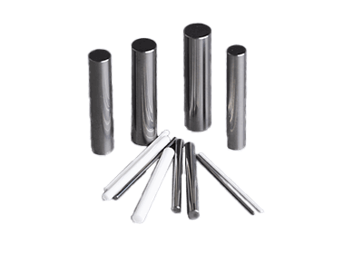
Pin gauges are precision measurement tools primarily used to assess the inside diameter of holes in products and determine whether the hole size conforms to a specified standard.

Typically, sets of pin gauges with varying thicknesses are available. When measuring hole diameters using a length measuring machine like a 3-point micrometer, where results are obtained numerically, variations can occur based on the skill of the person performing the measurement.

However, pin gauges provide stable and consistent measurements, reducing variability regardless of the operator’s skill level.

Applications of Pin Gauges

Pin gauges find extensive use in the manufacturing and quality control processes of industrial products. They are especially valuable for measuring the inside diameter of small holes, which cannot be accurately measured with instruments like a 3-point micrometer. Pin gauges are employed to determine whether the hole diameter falls within the specified tolerances.

Furthermore, pin gauges can be utilized to measure the distance between two holes. By inserting pin gauges without play into each of the two holes, measuring the outer diameters of the pin gauges with a vernier caliper, and subtracting the radii of the pin gauges, the center-to-center distance between the two holes can be calculated.

Pin gauges also play a role in measuring gears. To evaluate the thickness of gear teeth, one parameter considered is the overpin dimension. This involves placing two Pin Gauges between gears, measuring the distance between the outer diameters of the pins, and using this measurement for assessing the thickness of gear teeth, both for external and internal gears.

Principles of Pin Gauges

Pin gauges belong to the category of measuring gauges.

These gauges are manufactured with strict control not only over their outside diameter but also regarding roundness and cylindricity. Due to their extremely high precision, pin gauges are inserted into the hole being evaluated. For instance, if a hole can admit a 3.05mm pin gauge but cannot accept a 3.10mm pin gauge, the bore diameter is determined to be within the range of 3.05mm to 3.10mm.

Additional Information on Pin Gauges

1. Handling of Pin Gauges

When handling pin gauges, temperature sensitivity should be taken into account. Most pin gauges have small diameters and low volume. Prolonged handling can lead to thermal expansion due to body heat.

Thermal expansion can cause the pin gauges to have a larger diameter than their indicated value. Despite their simple cylindrical design, pin gauges must be handled with care. Scratches on their surface can compromise their accuracy. Moreover, rust formation is a significant concern, especially for steel or superalloy pin gauges. Handling them with bare hands can introduce salt from sweat, leading to rust.

It is advisable to wear gloves when handling metal pin gauges. After handling them with bare hands, they should be wiped with a clean, soft cloth or leather and lightly coated with anti-corrosive oil.

2. Distinction from Plug Gauges

Plug gauges, like pin gauges, are inserted into the hole for evaluation. Plug gauges have two differently sized cylinders at each end, with one end serving as the “go” side and the other as the “no-go” side. This design allows for a quick determination of whether the inside diameter of the hole falls within the standard range.

Plug gauges are commonly used for holes with larger inside diameters compared to pin gauges since they facilitate relatively quick and straightforward inspections.

3. Materials Used in Pin Gauges

Pin gauges can be made from materials such as steel, cemented carbide, or ceramic.

Ceramic pin gauges are known for their ease of maintenance. They do not rust since they are not made of metal. However, they still require careful handling and should not be treated roughly simply because they do not corrode.

カテゴリー
category_usa

Chip Fuse

What Is a Chip Fuse?

Chip FusesA Chip Fuse is a type of chip component mounted on a circuit board.
It has the role of preventing accidents caused by melting even if an overcurrent flows and generates heat due to a circuit malfunction. The structure is almost the same as that of a chip resistor, but instead of a resistive element, a metal with a low melting point is used as the fusing element.

Uses of Chip Fuses

Chip Fuses are mounted on a circuit board. Examples of specific applications include battery-powered communication devices such as smartphones and cellular phones, portable-type audio equipment, and electronic circuits in cameras and other photographic equipment.

The purpose is to prevent accidents in the event of an overcurrent due to a malfunction of an element on the circuit board. However, like ordinary fuses, they are not intended for use in power circuits to which commercial power is connected.

This is because chip fuses are small in size, do not provide sufficient insulation distance, and cannot carry a large current. Chip fuses are intended only for the protection of certain circuits and boards.

Principle of Chip Fuses

A Chip Fuse is a single-layer or multi-layer ceramic substrate with a fusing element that conducts electric current. The fusing element is based on a relatively high conductivity material such as copper, gold, or copper-tin or silver-palladium alloys, and therefore the fuse resistance is small.

The fusing element is also made of laser-trimmed thick film deposits or etched metal layers to achieve the required characteristics. In other words, the shape and thickness are set so that the fusing element melts after a certain period of time under overload, when the current flowing through the Chip Fuse exceeds its rated value.

In addition, the fusing element must be protected from various ambient conditions in order for the Chip Fuse to operate reliably.

Multilayer Chip Fuses are surrounded by a ceramic substrate layer, so the fusing element does not need a special protective coating.

On the other hand, in single-layer Chip Fuses, the elements are usually coated with lacquer or epoxy as a protective coating to prevent changes in their characteristics.

In addition, there are various types of fuses, such as fast-acting types and inrush-resistant types that do not easily fuse with rush currents, and each type has different fusing characteristics.

If the fusing characteristics are not taken into consideration, the fuse may blow even during normal operation, while at the same time, circuit protection may not function in the event of an emergency, etc. Therefore, it is important to select a fuse with optimal fusing characteristics for the circuit in use.

How to Select Chip Fuses

If the current flowing through the circuit is constant, fuse selection is easy. In the event of a short circuit or other abnormal condition, the current is much higher than normal, so there is no problem if you select a fuse that will blow immediately when the operating current of the circuit is exceeded. Therefore, for circuits where a nearly constant current flows, a type of fuse called a “quick-opening type” should be selected.

However, the actual current flowing in a circuit is not constant in most cases, but varies in a complex manner depending on the operating conditions. For example, if a capacitor with a large capacitance is connected to a power supply circuit, an inrush current many times greater than the steady-state current will flow when the power is turned on. It is inevitable that a large current flows when a motor starts up (from the time power is turned on until rotation stabilizes).

Such rush current is normal, but depending on the fuse selection, the rush current may cause the fuse to blow. On the other hand, it is undesirable to set a fuse with a large current rating with a large margin, since this will reduce safety. In such cases, one countermeasure is to use “inrush-resistant fuses,” which have a characteristic of not blowing at a short period of rush current.

1. Rush Current

It is difficult to determine the relationship between the rush current in a circuit and the fuse blowing, and the waveform and time of the current must be carefully examined in relation to the fuse’s blowing characteristics.

It is necessary to select a fuse with appropriate fusing characteristics based on the change over time of the heat generated by the fuse. Fuse manufacturers provide many materials for this purpose, and we recommend that you make use of these materials. 

2. Rated Voltage

Fuses are treated the same as wires in circuit design, but in practice they have a small resistance value, so some voltage drop is inevitable. Especially since recent electronic circuits have lower operating voltages, it is necessary to check the effects of such voltage drops.

Fuses also have a rated voltage and should always be used at or below that voltage. If Chip Fuses are used above their rated voltage, there is a risk of arcing after fusing, causing them to conduct again.

3. Rated Current and Derating

Derating is a consideration in the rated current. In the case of fuses, there are two types of derating: the common derating, where the fuse is selected so that the steady-state current of the circuit is less than 70% of the fuse’s rated current (varies slightly from fuse manufacturer to fuse manufacturer).

The other is derating for temperature. The derating should correspond to the ambient temperature of the board on which the fuse is mounted. In general, the amount of derating should be checked in the fuse manufacturer’s catalog or data sheet.

4. Other

In the case of glass tube fuses and the like, even if they blow due to excessive current, continuity can be restored by replacing the fuse after repairing the faulty part. Chip Fuses, however, are not intended to be replaced. In other words, when a Chip Fuse blows, the entire circuit board must be repaired and replaced instead of replacing the fuse.

In addition, it is difficult to visually confirm whether a Chip Fuse has blown or not. Although it is possible to electrically confirm blown fuses by using a tester, it is not possible to judge the blown fuse from its external appearance, as is the case with glass tube fuses.

カテゴリー
category_usa

Vacuum Controllers

What Are Vacuum Controllers?

Vacuum controllers are control devices designed to maintain a constant level of vacuum in a measurement environment.

They consist of a sensor for measuring the vacuum level, a solenoid valve for control, and valves for connecting to the measurement environment and the vacuum pump.

By integrating all these functions into a single unit, vacuum controllers are easy to maintain, including monitoring the vacuum level.

Applications of Vacuum Controllers

Vacuum controllers are used in environments where a constant vacuum is required for various purposes:

  • Vacuum control in working processes of concentrators and distillation equipment
  • Environmental measurements in clean rooms, laboratories, etc.
  • Other experimental processes in laboratories, research facilities, etc.
  • Vacuum control during industrial production

They are used for measuring and controlling the degree of vacuum in closed containers as well as for measuring the pressure of an entire room.

Additionally, using a chemical-resistant sensor (e.g., made of ceramic), pressure other than atmospheric can also be measured and controlled.

Principles of Vacuum Controllers

Vacuum controllers utilize pressure sensors to measure absolute pressure and employ solenoid valves for controlling the vacuum line and atmospheric release to maintain a constant vacuum.

These controllers integrate the sensor, solenoid valve, and valve into a single unit, eliminating the need for a separate control device.

The accuracy of the sensor is crucial since the value used for control is measured by the sensor. Regular inspection and replacement of sensors when necessary are essential maintenance tasks.

Some manufacturers offer the option to replace only the sensor. Sensors are made of materials such as ceramic or silicon semiconductor for different applications, including large-capacity vacuum vessels and corrosive gases.

Many vacuum controllers come equipped with mounting clamps on the back, making it easy to secure them to existing structures. Some feature mechanisms to prevent the boiling of solvents collected during the control process and are made of materials with excellent solvent resistance.

Furthermore, certain products are capable of operating during power outages.

カテゴリー
category_usa

Vacuum Cleaners

What Are Vacuum Cleaners?

Vacuum Cleaners

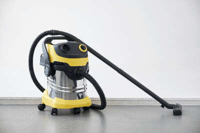
A vacuum cleaner is a cleaning tool that sucks dirt and dust through an air inlet.

The performance of a vacuum cleaner depends on its suction power and the size of the dust that the filter can filter (diameter of the holes).

It can be said that the better the suction ability to suck in dust and the smaller the size of dust that the filter can filter, the better the performance.

There are two types of vacuum cleaners available: commercial vacuum cleaners with 12~30 liter capacities and industrial vacuum cleaners with 30~170 liter capacities.

Applications of Vacuum Cleaners

Vacuum cleaners are mainly used in the food, pharmaceutical, medical, chemical, precision instrument, electronic, construction, hotel, office, and metal, automotive, concrete, and industrial waste industries to clean up hazardous dust in the work environment.

Examples of applications include:

  • Metalworking, steel mill dust
  • Industrial production cleanup
  • Food factories
  • Pharmaceutical plants, clean rooms in pharmaceutical facilities
  • Clean rooms in laboratories
  • Dust in workshops and for DIY, ready-mixed concrete plants
  • Cleaning of warehouses, shells, bicycle parking lots, demolition and renovation sites
  • Cleaning of control components, electrical components, PC components and peripherals
  • Cleaning of buildings, offices and stores
  • Cleaning of gardens and artificial turf

Principle of Vacuum Cleaners

The vacuum cleaner consists of three parts:

  • An inlet part (air inlet) where air containing dirt and dust comes in.
  • The filter part (dust catcher made of filter material), which removes dirt and dust and allows only clean air to pass through
  • The vacuum cleaner, which creates a weak level of vacuum by the rotation of the motor.

Filters used include synthetic fiber filters, cartridge filters, sponge filters, and sludge filters.

The blower, connected to a motor that rotates more than 10,000 times per minute, blows air out of the vacuum cleaner like a ventilation fan.

As a result, the interior of the vacuum cleaner becomes lower than the outside air pressure, creating a vacuum. Since gas has the property of moving from high pressure to low pressure,
outside air with high pressure is sucked into the vacuum cleaner at low pressure along with dust.

Contaminated air sucked along the hose collects in a dust bag (filter) with micro holes. Only the clean air that can pass through the fine holes passes through the filter and
goes out again through the exhaust port, leaving only dust in the filter.

カテゴリー
category_usa

Chip Tray

What Is a Chip Tray?

A chip tray is a container for storing various chip-shaped components such as wafer chips, prisms, lenses, and crystals.

By placing semiconductor products, glass products, and other products for which dust adhesion or minute scratches can cause serious damage in a chip tray, it is possible to store and transport these products without compromising their functionality.

In addition, since a chip tray is compartmentalized inside, it can eliminate problems such as damage caused by collisions between contents during transportation, or mixing of contents that makes them indistinguishable from each other.

Uses of Chip Trays

Chip trays are used to store products in chip form in a compartmentalized case to protect them from dust and scratches.

Therefore, they are used as storage containers for wafer chips and semiconductor chips cut from silicon wafers used in semiconductors, as well as ball lenses and hemispherical lenses used in precision equipment.

Many of these products are manufactured in clean rooms, which are spaces under cleanliness control. Products are stored and transported in chip trays when they are carried outside the clean room for transportation to the next process or shipment.

Principle of Chip Trays

Most of the products stored in chip trays, such as wafer chips and glass lenses for precision instruments, are products that must not be scratched even slightly, so plastic, a relatively soft material that is resistant to fibers and other debris, is used for chip trays.

In addition, many of the components stored in chip trays are electrically sensitive products such as semiconductor products. Since these products may be damaged by static electricity accumulated in the trays, conductive polystyrene or antistatic ABS are used among plastics to prevent static electricity from accumulating.

Chip trays are manufactured in a variety of materials and colors, such as Bakelite or carbon fiber when heat resistance is required depending on the operating environment, or black when storing products that are sensitive to ultraviolet rays.

Since chip trays are often used in clean rooms, many chip tray products are pre-packed (manufactured in a clean room and shipped vacuum-packed).