カテゴリー
category_usa

Digital Differential Pressure Gauge

What Is a Digital Differential Pressure Gauge?

Digital Differential Pressure Gauges

A Digital Differential Pressure Gauge is a device that measures and digitally displays the difference in pressure between two points.

It is sometimes called a manometer. The main features of a Digital Differential Pressure Gauge are its simplicity, which allows differential pressure to be measured simply by connecting the two points to be measured with a measuring tube, and its small size and light weight. Many products are available for both gases and liquids.

They can be used for a wide range of applications, from relatively large differential pressure, such as air pressure in air conditioning equipment, to small differential pressure in clean rooms, and can also be used for a wide range of ranges and resolutions. The battery-powered type, which does not require wiring, is used for monitoring and recording equipment, while the type with an alarm device is used for maintenance such as filter replacement. Some of them can measure flow rates using pitot tubes.

Applications of Digital Differential Pressure Gauge

Digital differential pressure gauges are used in a wide range of applications due to their broad measurement resolution. Typical applications are as follows

1. Performance Check of Air Conditioning Equipment

2679_Digital-Differential-Pressure-Gauges_デジタル差圧計-1.png

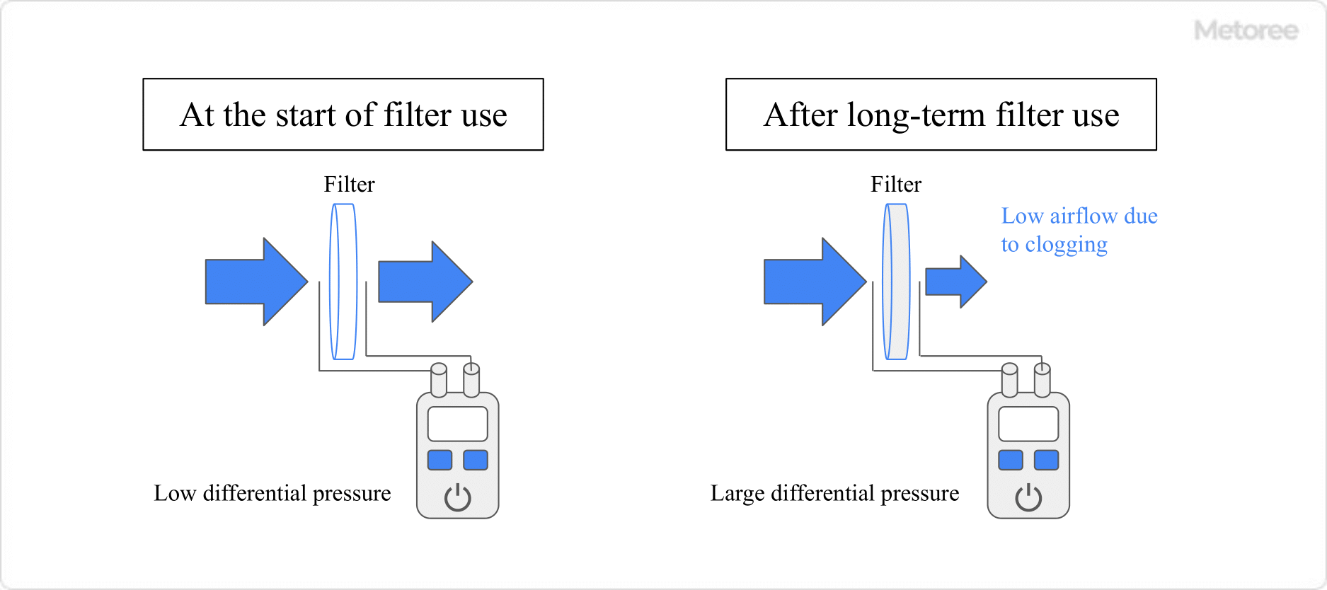
Figure 1. Maintenance of filter deterioration

Air conditioning equipment includes ducts, fans, and filters. As shown in Figure 1, the performance of filters deteriorates due to clogging after long-term use.

As clogging of the filter progresses, the differential pressure before and after the filter increases, so the performance of the filter can be checked using a differential pressure gauge.

2. Environmental Measurement in a Clean Room

2679_Digital-Differential-Pressure-Gauges_デジタル差圧計-2.png

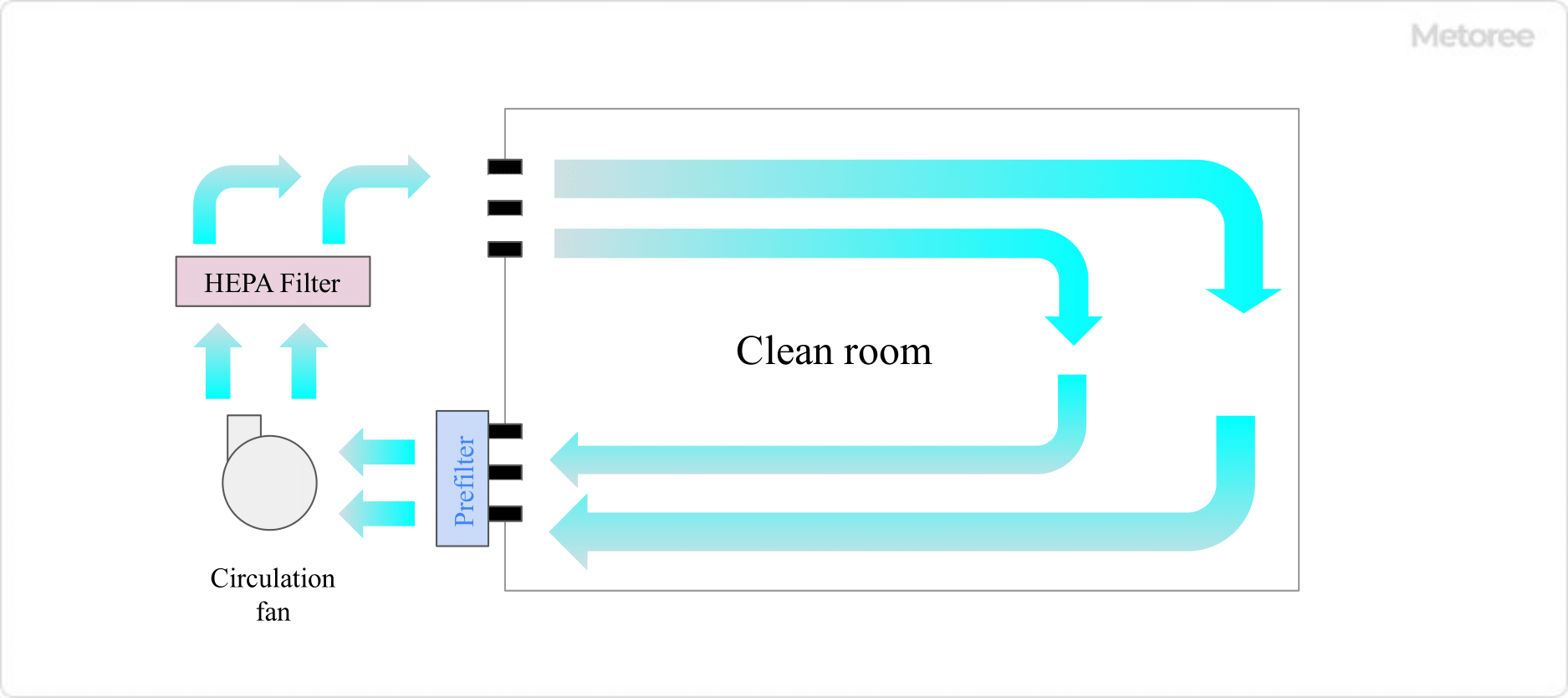
Figure 2. Schematic diagram of a clean room

In a clean room, it is important to maintain air cleanliness. Air is constantly circulated, and filters are used to remove dust and other particles to maintain cleanliness. It is important to check the performance of the filter using a differential pressure gauge.

The inside of the clean room is kept at positive pressure (higher than 1 atmospheric pressure) to prevent dust and other contaminants from being drawn in from outside the clean room. A differential pressure gauge can be used to check whether positive pressure is maintained. Especially when some kind of exhaust system is installed in the clean room, it is essential to check the positive pressure because negative pressure is likely to occur.

3. Level Measurement of Large Sealed Tanks

2679_Digital-Differential-Pressure-Gauges_デジタル差圧計-3.png

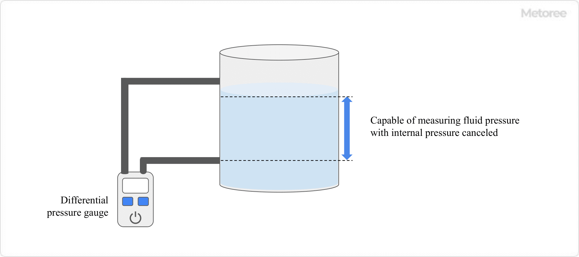
Figure 3. Measuring liquid level height in a sealed tank using a differential pressure gauge

A differential pressure gauge is also used to determine the level (height of the liquid surface) of a liquid in a closed tank. If the specific gravity of the liquid is constant, the pressure applied to the measuring surface is proportional to the level of the liquid, so the level can be determined by measuring the pressure.

However, in the case of a sealed tank, the pressure applied to the measurement surface includes the internal pressure of the tank top surface, so it is necessary to cancel the effect of the internal pressure. In such cases, a differential pressure gauge can be used to measure only the pressure due to the liquid.

Principle of Digital Differential Pressure Gauge

When pressure is applied to a pressure-sensitive element, the deflection of the element is measured as an electrical signal by the change in resistance due to the current flowing through the element. The relationship between the electrical signal and the displacement of the element is used to convert the measurement result into pressure. Digital Differential Pressure Gauge displays the difference in pressure between two points measured in this way as a digital value.

Since the Digital Differential Pressure Gauge has two measuring points, it measures the magnitude and direction of the deflection (displacement) caused by the pressure applied from the two measuring points in two directions. By measuring the direction, it determines which is the high pressure side and which is the low pressure side, and the difference in displacement is read as an electrical signal and displayed as a pressure difference.

Other Information on Digital Differential Pressure Gauge

About the Pressure-Sensitive Element

Embedded inside a Digital Differential Pressure Gauge is a piezoelectric element (piezoelectric element) as a pressure-sensitive element. A piezoelectric element is a passive element that uses the piezoelectric effect to generate a voltage in response to the pressure applied to a specific material. Crystal (synthetic quartz) and ceramics with strong magnetic properties are mainly used.

The piezoelectric element, which is the key to measurement, consists of a piezoelectric material with the piezoelectric effect sandwiched between two electrodes. The simple structure of the piezoelectric element has the advantages of being durable, resistant to deterioration, and lightweight.

There are many materials that possess the piezoelectric effect, and since materials for pressure-sensitive elements are being developed, products that enable more precise measurement are also being developed.

カテゴリー
category_usa

Digital Pressure Sensor

What Is a Digital Pressure Sensor?

A digital pressure sensor is a device that digitally displays the pressure inside a pipe.

This display method has the advantage of reducing the risk of misreading and can be used in dark locations. Digital pressure sensors measure pressure by means of an internal piezoelectric element. Therefore, measurement can be made without directly touching the fluid flowing in the piping.

The sensor used should be changed according to the type of fluid. They are divided into those for liquids, gases, flammable fluids, and so on. In addition, since the sensor is fixed to the piping, attention must be paid to the diameter of the piping.

Uses of Digital Pressure Sensors

While digital pressure sensors are rarely used in the average home, they are used very extensively in industry. In industrial facilities and plants, fluids (e.g., water or oil) are moved through pipes to various devices. A certain force is required to pump the fluid, and this force creates a pressure above atmospheric pressure.

Theoretically, if the same force is applied to the same fluid, the resulting pressure should be the same. However, equipment failure or deteriorating piping can result in pressures that differ from expected pressures.

By detecting and recording these unexpected changes in pressure, digital pressure sensors play an important role in detecting problems at an early stage and contributing to quality control.

Principle of Digital Pressure Sensors

Digital pressure sensors measure pressure when a force is applied to the piezoelectric element contained in the sensor. When pressure is applied, an electric current corresponding to the force is generated, which is processed and displayed as an electrical signal. A typical example of a piezoelectric element is a semiconductor. A semiconductor is a substance that conducts electricity under certain conditions.

Unlike insulators and conductors, the timing of electricity flow can be freely changed by manipulation. The most commonly used material is silicon. A flexible membrane (diaphragm) is attached to a silicon substrate. When pressure is applied, the diaphragm bends, and the silicon substrate bends along with it.

The force causes a piezoelectric effect that changes the state of charge in the substrate, resulting in a voltage. Since the intensity of the current flow changes with the voltage, it is possible to measure how much pressure is applied.

There are also other types that attach a resistive bridge to the diaphragm and measure the amount of strain on the diaphragm as a voltage change. When using the amount of strain, a metal diaphragm is used, and stainless steel is mainly used.

Types of Digital Pressure Sensors

Digital pressure sensors are classified into a wide variety of types according to their application, sensitivity, shape, and scaling range. The major types are listed below.

1. Absolute Pressure Sensor

Absolute pressure sensors can measure pressure with respect to a vacuum. Generally, atmospheric pressure is considered to be one atmosphere, but this type of sensor is based on absolute zero.

This sensor is mainly used for weather forecasting, altimeters, and cleaning equipment.

2. Gauge Pressure Sensor

Gauge pressure sensors can measure pressure with respect to the current atmospheric pressure. In other words, these sensors can read relative pressure changes. These sensors are used for tire pressure measurement in automobiles, air conditioner pressure management, etc.

3. Differential Pressure Sensor

Differential pressure sensors can measure the pressure difference between two pressure sources. These sensors are primarily used to detect clogged filters or to monitor liquid flow.

4. Shield Pressure Sensor

Shielded pressure sensors can set a specific reference pressure and measure the pressure relative to that pressure. They are primarily used for telemetry and data logging.

How to Select a Digital Pressure Sensor

When selecting a digital pressure sensor, many factors should be considered, including the operating environment, fluid of interest, measurement range, and accuracy.

1. Operating Environment

Sensors can be affected by environmental conditions such as high or low temperature, humidity, and vibration. Therefore, it is important to carefully consider the operating environment when selecting a sensor.

2. Target Fluid

The appropriate sensor depends on the type of liquid or gas. Especially when handling corrosive liquids or food, it is necessary to check the resistance of the sensor to the target substance.

3. Measuring Range and Accuracy

The measuring range and accuracy of the sensor are also important selection criteria. It is important to confirm how accurately the sensor can measure within the desired pressure range.

4. Ease of Installation and Operation

Ease of installation and operation of the sensor is also important. The appropriate interface and installation method must be selected in consideration of the location of the sensor and the skill level of the person using the sensor.

カテゴリー
category_usa

Digital Angle Meter

What Is a Digital Angle Meter?

A digital angle meter is a measuring instrument for measuring inclination or angle.

It uses a digital liquid crystal display to display measured values. Unlike analog inclinometers, digital inclinometers can be set to an arbitrary position as a reference and measure angles relative to the reference. It can respond to the high measurement accuracy and wide measurement range required for research and industrial applications.

For this reason, it is used in work such as plumbing, drainage, steel-frame building construction, equipment installation, and medical equipment. There are two main methods of measuring angles: one utilizing MEMS technology and the other utilizing electrolyte inclination.

Uses of Digital Angle Meters

1. Cutting and Construction Sites

Digital angle meters are used to measure the angle of incidence of drills at cutting sites. If the angle deviates from the target angle, the cutting direction will change, leading to wasted work and danger.

They are also useful for measuring the angle of cranes at construction sites. By measuring angles, hazards can be predicted. Horizontal and vertical measurements of steel frames and piping can be easily made.

2. Photovoltaic Panels

Used for solar tracking of photovoltaic panels. Attached directly to the object to be measured for the purpose of obtaining sufficient charge.

3. Other

One of the applications is to set the horizontal/vertical axis of precision machines, measuring instruments, distribution boards, etc. during installation. It is used to measure the arm angle of robots and other automatic equipment.

Furthermore, digital angle meters are also utilized in the medical industry, where they are used to accurately determine the angle of the measuring rotator in CT and X-ray equipment. The positioning of the bed on which the patient lies leads to the accuracy of locating lesions in the human body.

Principle of Digital Angle Meters

1. MEMS Method

Inclinometers utilizing MEMS (Micro Electro Mechanical Systems) technology place electrodes in an array inside a fully enclosed chamber. One of the two poles is fixed, while the other pole is freely movable in connection with a spring spring.

When the sensor is tilted, the position of the electrode at the free end changes relative to the electrode at the fixed end, and at the same time, the capacitance differs before and after the change. The difference in capacitance at that time is converted to an angle.

2. Electrolyte Method

In an inclination sensor utilizing electrolytic solution technology, two pairs of electrodes are mounted on the bottom of a chamber parallel to the measurement axis and filled with electrolytic solution. When voltage is applied between the two electrodes, the current forms a dispersion field. As a result, the chamber tilts and the liquid level changes, so does the dispersion field.

The conductivity of the electrolyte is constant, and the change in resistance depends on its relationship to the liquid level. In addition, since there are no moving parts other than the electrolyte, there is little wear and tear, and the electrolyte is highly shock resistant. The electrode used for measurement is immersed in the electrolytic solution, and the electrode does not corrode.

Characteristics of the Digital Angle Meter

1. V-Shaped Cut & Built-in Magnet

The measuring surface of most digital angle meters is cut in a V-shape for excellent stability even on a pipe. The bottom surface is also equipped with a built-in magnet, making steel pipe, steel frame, and plant construction more efficient.

2. High Accuracy

High resolution and accuracy can be displayed digitally on 2 axes simultaneously. Comprehensive solutions for accurate leveling, alignment, surface profiling, and vibration measurement are available. Accuracy is often around ±0.03 to 0.2° and resolution around 0.01 to 0.1°. And it eliminates the trial-and-error process of reading one axis at a time, saving time and enabling high quality professional work.

3. Comparative Display

Any angle can be used as the reference 0° and displayed in comparison with other angles. For example, if a 30° position is set as reference 0° in comparison mode, a 50° position in normal mode will be displayed as 20°.

4. Dustproof and Waterproof Performance

The camera can be used safely even with wet hands or in dusty areas on site. Most of the dustproof and waterproof performance is equivalent to the IP54 standard set by the IEC (International Electrotechnical Commission).

カテゴリー
category_usa

Digital Thermostat

What Is a Digital Thermostat?

Digital thermostat are electronic devices that control temperature by measuring it through sensors like thermocouples, resistance thermometers, and thermistors. They calculate the temperature from the output signal of these sensors and regulates heating or cooling devices to maintain the desired temperature. Users can digitally set and monitor temperatures, enabling precise control over environmental conditions.

Uses of Digital Thermostats

Digital thermostats are essential in various settings for accurate temperature management. They are versatile, supporting applications from food warming to incubator temperature regulation. With features like automatic and manual reset controls, they serve critical roles in safety and process management, preventing overheating and serving as temperature alarms in sensitive operations.

Principle of Digital Thermostats

Digital thermostats operate by analyzing signals from temperature sensors to accurately control an environment’s temperature. They utilize thermocouples, resistance thermometers, or thermistors to detect temperature changes and generate corresponding electrical signals for heating or cooling adjustments. Compatibility with sensors from different manufacturers is ensured by adherence to industrial standards.

Types of Digital Thermostats

Digital thermostats come in various types tailored to specific needs and functionalities:

  • Simple On/Off Control: Basic temperature regulation by switching heating or cooling devices on and off to maintain set temperatures.
  • PID Control: Offers precise temperature management by adjusting control signals based on the set temperature deviation, minimizing fluctuations.
  • Programmable Digital Thermostats: Allows scheduling different temperatures for specific times or days, optimizing comfort and energy efficiency.
  • Wi-Fi / Smart Digital Thermostats: Enables remote temperature setting and monitoring through Wi-Fi or smart devices, offering convenience and control.
  • Learning Digital Thermostats: Adapts to user preferences over time, automatically adjusting to provide optimal temperature settings.
カテゴリー
category_usa

Digital Isolator

What Is a Digital Isolator?

Digital Isolators

A digital isolator is a device used to isolate the transmission and reception of digital signals.

Insulation” is very important in electrical circuits, preventing equipment from shorting out or being damaged. In addition, having the necessary parts well insulated prevents current from flowing to other parts of the circuit, which helps eliminate noise and send normal signals.

Furthermore, digital isolators are electronic devices that are expected to be applied to a wide variety of equipment due to their long life and low power consumption.

Uses of Digital Isolators

Digital isolators are widely used in devices that require insulation in electronic circuits. First of all, they are used in industrial machinery where there are large voltage differences among devices. Power supplies that require large voltages or large motors and parts that operate with small voltages are located close together and must be isolated where there is a large voltage difference.

This is to prevent damage caused by the application of high voltage to parts that operate at low voltages. Next, it is also used for medical equipment such as X-rays and AEDs. These medical devices are often used with the hands, and the purpose is to prevent electric current from flowing outward and causing an electric shock.

In automobiles, digital isolators are used to protect ECUs and other in-vehicle devices in vehicles that use high-voltage power supplies, such as electric vehicles and hybrid vehicles.

Principle of Digital Isolators

There are two types of digital isolators: magnetic isolation and capacitive isolation.

1. Magnetic Isolation Method

Digital isolators with magnetic isolation use coils on the transmitting and receiving sides, respectively. By using coils on the transmitting and receiving sides, conversion between electric signals and magnetic energy is performed.

It can handle high speeds, but the disadvantage is that the faster the speed, the higher the current consumption. In addition, noise characteristics are inferior to those of the following capacitance-isolation type.

2. Capacitive Isolation Method

This is a digital isolator using a capacitor. In transmission and reception, electrical signals are converted into charge and discharge by using capacitors. The capacitive isolation method has particularly excellent noise characteristics and, like the magnetic isolation method, can be used at high speeds. In addition, current consumption is not related to speed, but rather is disadvantageous at low speeds.

Both methods have the advantage of long life and high speed, and have superior performance compared to previous isolators. However, the only disadvantage is that digital isolators can only handle digital signals and not analog signals.

Structure of a Digital Isolator

The structure of a digital isolator with magnetic isolation consists of two coils arranged in a super engineering plastic called polyimide. A pulse current is applied to one coil to generate a small local magnetic field, which in turn generates a current in the other coil.

A capacitively isolated digital isolator consists of a capacitor with a thin silicon dioxide (SiO2, silica) insulation layer.

Characteristics of Digital Isolators

Digital isolators have the following advantages over conventional optical isolators

1. High Dielectric Strength

Digital isolators are characterized by their large dielectric strength. The dielectric strength of optical isolators ranges from 1 to 20 Vrms/μm, while that of digital isolators with magnetic isolation is 300 Vrms/μm and 500 Vrms/μm for capacitive isolation, 10 to 200 times higher than that of optical isolators.

2. Long Life

Digital isolators are characterized by their long life. While optical isolators have a life expectancy of about 10 years, digital isolators are said to have a life expectancy of 25 years or more.

3. High Response Speed

While optical isolators can isolate signals up to about 20 Mbps, digital isolators can handle speeds of 150-200 Mbps, or about 10 times faster.

4. Low Current Consumption

Digital isolators can keep current consumption low. In particular, the capacitive isolation type can reduce current consumption regardless of the speed.

カテゴリー
category_usa

Digital pH Meter

What Is a Digital pH Meter?

A digital pH meter is an instrument used to measure the pH of a solution.

It is expressed as a number between 0 and 14, with a value of 7 indicating neutrality, a value less than 7 indicating acidity, and a value greater than 7 indicating alkalinity.

A digital pH meter can be used to read the hydrogen ion concentration index of a solution as a digital value. pH is called “pH” or “pH (pHH),” but JIS Z8802:2011 states that it should be read as “pH or pHH.

Uses of Digital pH Meters

Digital pH meters are used for environmental measurement and chemical analysis. In environmental measurements, digital pH meters are used for water quality control of drinking water and wastewater, and in chemical analysis, digital pH meters are used for quality control in laboratories and on industrial production lines.

In chemical analysis, pH is one of the indicators that affect sample pretreatment and analysis conditions. pH also affects the progress of chemical reactions, making it an important control item at manufacturing sites.

Principle of Digital pH Meters

The measurement method most commonly used in digital pH meters is the glass electrode method. The glass electrode method uses two electrodes (a glass electrode and a reference electrode). When a liquid with a different pH is present in the two areas separated by the glass films of the electrodes, an electromotive force corresponding to the difference is generated, and the pH is calculated by measuring the potentials of the glass and reference electrodes in the main unit.

Note that the pH meter must be calibrated before use. pH standard solutions are generally calibrated with pH 7 as the zero point and pH 4 and pH 9 as the three-point calibration, but the pH standard solution used for calibration may be changed depending on the pH of the sample. It should also be noted that the slope of the calibration curve is affected by temperature.

To measure pH accurately, the temperature of the pH standard solution and the sample must be matched as much as possible, the electrode must be properly maintained, and the electrode’s drop must be immersed in the sample. pH measurement itself is a simple task, but it is important to keep in mind the key points during measurement and to establish a maintenance method. It is important to follow the procedure for the measurement and maintenance of the electrode.

Other pH measurement methods besides the glass electrode method include the use of indicator such as litmus paper, hydrogen electrode, quinhydrone electrode, and antimony electrode methods.

Other Information on Digital pH Meter

1. Calibration of Digital pH Meter

Calibrating a pH meter means correctly adjusting the zero and span points (sensitivity) of the pH meter using a pH standard solution. Since there are specific operations depending on the digital pH meter used, the instructions provided with the meter should be given priority when performing the actual calibration.

There are three types of calibration: one-point calibration using one type of pH standard solution, two-point calibration using two types, and three-point calibration using three types, but two-point calibration is often used to calibrate pH meters. One-point calibration is a simplified calibration. For more rigorous calibration, three-point calibration is used.

The actual value of “electromotive force per pH” at a glass electrode is affected by contamination of the glass film and “alkaline error” and “acid error” (errors in strong alkaline and strong acid conditions, respectively). Therefore, the actual value is generally lower than the theoretical value (59.16mV at 25°C). The “pH7 EMF” also deviates from the theoretical value (0mV).

By performing calibration prior to measurement and periodically, highly accurate pH measurement can be achieved.

2. Calibration Solution for Digital pH Meter

The types, quality, and composition of pH standard solutions are as follows.

Oxalate pH Standard Solution
0.05mol/kg potassium trihydrogen dioxalate solution, pH 1.68 at 25°C

Phthalate pH Standard Solution
0.05mol/kg potassium hydrogen phthalate in aqueous solution, pH 4.01 at 25°C

Borate pH Standard Solution
0.01mol/kg sodium tetraborate aqueous solution, pH 9.18 at 25°C

Carbonate pH sStandard Solution
0.025mol/kg sodium bicarbonate and 0.025mol/kg sodium carbonate solution at pH 10.02

Neutral Phosphate Standard Solution
0.025mol/kg potassium hydrogen phosphate, 0.025mol/kg disodium hydrogen phosphate solution, pH 6.86 at 25°C

カテゴリー
category_usa

Teflon Seal

What Is a Teflon Seal?

Teflon Seals

A Teflon seal is a material (sealing material) made of a fluoropolymer called Teflon or PTFE (polytetrafluoroethylene) that is used to maintain sealing properties.

A seal is broadly defined as a plastic material that seals a gas or liquid leak, but is also referred to as a packing or gasket. Packing and gasket refer to parts that are sandwiched together to create a tight seal at a joint.

However, “seal” is not limited to parts; it also includes tape that is wrapped around a joint.

Uses of Teflon Seals

Teflon seal is used, for example, in the form of tape that is wrapped around the threads of a piping joint to ensure a tight seal. This is also known as “thread sealing tape.

It is also used as a gasket to seal vacuum flanges to prevent atmospheric inflow. Another application is to prevent dust from entering from the outside (dust seal).

Thus, Teflon seals are widely used in hydraulic and hydraulic equipment under low to high pressure conditions, mainly to prevent leakage of fluids such as oil and water.

Characteristics of Teflon Seals

Teflon seals are used in a wide range of applications because of their excellent heat and cold resistance (thermal properties), insulation properties (electrical properties), and chemical stability and resistance to a wide range of chemicals (chemical properties). Teflon’s properties, which are not found in other industrial materials, make it suitable for use in harsh conditions, ranging from vacuum to high-pressure environments.

Teflon is highly stable against acids, alkalis, and organic solvents, and rarely corrodes or swells. It also exhibits strong resistance to ozone gas. In addition, Teflon has no electrical polarity (nonpolar) due to the symmetry of its molecular structure.

Therefore, parameters such as dielectric constant and power factor are constant regardless of temperature and frequency, and insulation resistance is extremely high. Even under high voltages of several tens of kilovolts, Teflon can demonstrate its performance without losing its insulating properties (→ similar to the principle of Teflon coating).

Molecular Structure of Teflon

Teflon is a thermoplastic polymer (softens and can be molded by heat) composed of fluorine elements and carbon chains. Its unique chemical, electrical and thermal properties are due to the molecular structure of Teflon itself.

Fluorine is stably bonded to the carbon chains in Teflon. The stability of this fluorine-carbon bond and the symmetry of the molecular structure are the source of Teflon’s performance.

It does not desorb even when heated up to a certain temperature, and its properties as Teflon are hardly lost. However, the melting point of Teflon is 327°C. Above this temperature, however, Teflon becomes gelatinous, and its mechanical properties drop sharply.

Types of Teflon Seals

Teflon seals come in a wide variety of forms, including gaskets, gaskets, and tapes. Some tapes are commonly referred to as VALQUA TAPE.

This is a tape-type sealing material manufactured by VALQUA Corporation, and its product name is TAPE SEAL®. It is often referred to as “Teflon seal” to refer to sealing Teflon tape made by companies other than VALQUA Corporation. In addition to tape-type sealing materials, fine thread-type sealing materials are also available.

Other Information About Teflon Seal

1. Teflon and PTFE as Names

Teflon® is a product name developed by DuPont of the United States in the 1930s. It generally refers to resins made of polytetrafluoroethylene (PTFE).

Although “Teflon” is currently used as a common name for PTFE, it is only a product name. In applications that are not DuPont products or not authorized by DuPont, the Teflon name is not used, but PTFE is used.

2. When Used as “Thread Sealing Tape” for Teflon Seal

Thinly wrap the tape around the threads of piping to be joined with screws, etc., and then screw in the parts to be joined. In this way, the high plasticity of the Teflon seal causes it to deform, tightly sealing the gap between the threads and creating a high-performance seal.

Due to the low friction of Teflon, the force required when screwing in is also tolerable.

カテゴリー
category_usa

Teflon Coating

What Is Teflon Coating?

Teflon™ (hereinafter referred to as “Teflon”) coating is a type of surface treatment for materials and is a surface treatment method of coating using Teflon, a fluoroplastic.

This “Teflon™” is a trademarked product by the former DuPont, now Chemours Corporation of the United States. Therefore, only processing manufacturers authorized and licensed by Chemours can use the “Teflon™” brand and name.

Uses of Teflon Coatings

Teflon coatings are used in a variety of fields, including:

  • Familiar household products
  • Aerospace equipment
  • Automotive components
  • Coating of electric wires

Teflon coatings are particularly suitable for surface treatment of seals, brake pads, and bearings in automobile transmissions, which are subject to high temperatures due to heat from the engine.

Principles and Characteristics of Teflon Coatings

1. Principle of Teflon Coatings

Teflon coating technology uses a fluorinated resin called Teflon. Teflon has excellent heat and solvent resistance and is electrically non-polar. Therefore, the coating film of Teflon coatings reflects the characteristics of Teflon.

Fluoropolymers other than Teflon are also manufactured by various companies, and coatings using these resins are also conventionally referred to as Teflon coatings.

What is Teflon?
Teflon is a thermoplastic polymer composed of fluorine elements and carbon chains that can be softened and molded by heat. The fluorine in Teflon is stably bonded to the carbon chain, and the excellent chemical, electrical, thermal, and mechanical properties of Teflon are attributed to this molecular structure.

There are nine types of Teflon, including PTFE (polytetrafluoroethylene), PFA (perfluoroalkoxyalkane polymer), and FEP (perfluoroethylene propane copolymer).

2. Properties of Teflon Coatings

Teflon has excellent heat and solvent resistance and is electrically nonpolar. The properties of Teflon coatings films reflect these characteristics.

1. Heat Resistance
Teflon coatings have high heat resistance and are not easily deformed by temperature changes. This is because Teflon has a structure in which fluorine and carbon chains are stably bonded, and its properties do not change up to a certain temperature.

For this reason, Teflon is used for surface treatment of automotive components that require heat resistance to withstand the high temperatures generated by engines and resistance to deformation due to temperature changes.

However, at temperatures above 327°C (620.6°F), the melting point of Teflon, the coating becomes a gel, and the mechanical properties of the coated film rapidly deteriorate.

2. Solvent Resistance
Teflon coatings have high solvent resistance. This is because Teflon has extremely high stability against acids, alkalis, and organic solvents.

3. Electrical Properties
Teflon coatings are electrically nonpolar. This is because Teflon has no electrical polarity due to the symmetry of its molecular structure. Parameters such as dielectric constant and power factor of Teflon are constant and unaffected by temperature and frequency, and the insulation resistance is extremely high.

For this reason, Teflon coatings are often used to sheath wires used in the electrical systems of personal computers, robots, and aircraft.

Other Information on Teflon Coatings

1. General Process of Teflon Coatings

There are various methods and processes for Teflon coatings, depending on the type of Teflon, the base material or base metal to be coated, and the purpose of use. The general processes are as follows.

  1. Preliminary diagnosis
    Inspect the base material to be coated for scratches, dents, welding points, etc. that may cause problems.
  2. Degreasing and air baking
    After degreasing to remove oil and adhering matter, the coating is air baked at a high temperature (about 300°C or 572°F). At this time, care should be taken if heat distortion is a problem.
  3. Roughening
    To remove stains and oxide film from the base metal, blast the surface with alumina abrasive.
  4. Primer (primer coat)
    An adhesive is applied to bond the base metal to the Teflon coatings. Primer is not necessary for self-adhesive fluoropolymer coatings.
  5. Drying
    Drying is performed at about 100℃ (212°F). Depending on the primer, high-temperature baking at 200°C (392°F) or higher may be required.
    Depending on the type of Teflon coatings, a middle coat may be required before the top coat in the subsequent process.
  6. Top Coat (Top Coating)
    Teflon coatings agent is applied using a spray gun, powder coating, or other prescribed method.
  7. Baking
    The Teflon coatings agent is baked at a specified temperature and time to harden it.
  8. Inspection
    Teflon coatings film is inspected for appearance, thickness, pinholes, etc.

2. Thickness of the Teflon Coatings

The thickness of the Teflon coatings film produced through the process described above varies depending on the intended use. Generally, the coating thickness is 20 to 50㎛ for non-adhesive purposes such as mold release improvement, and 300㎛ to 2mm for corrosion resistance purposes such as maintaining the functional appearance of molds.

Very special coatings can be produced with a very thin film thickness of as little as 1㎛. Pinholes in the coating film are an extremely important issue in Teflon coatings. For this reason, thicker coatings are sometimes used to prevent pinholes. For example, coatings thicker than 250㎛ is called “lining”.

カテゴリー
category_usa

Tesla Meter

What Is a Tesla Meter?

Tesla Meters

A Tesla Meter is an instrument for measuring the magnetic field (magnetic flux density) in a space. It measures the magnetic flux density per unit area.

Tesla Meters display the magnetic flux density in units of gauss or tesla using the Hall effect, an electrical property of semiconductors.

Generally, the stationary type has high accuracy and resolution, and can measure even in strong magnetic fields. They are used to verify the strength of magnetic fields not only in R&D and academic applications, but also in manufacturing and quality assurance.

Uses of Tesla Meter

Tesla Meters are used to verify the strength of magnetic fields not only in R&D and academic applications, but also in manufacturing and quality assurance. For example, Tesla Meter is used to measure powerful electromagnets (~10T) used in accelerator facilities.

Another application is in product quality control, where measurements are made to determine the magnetism of magnetic flux leakage, or the properties of magnetic materials.

Furthermore, it is also useful for measuring geomagnetism, since the earth also maintains a magnetic field (~nT), albeit a weak one.

The appropriate instrument should be selected according to the magnitude and type of the magnetic field to be measured and the required accuracy.

Principle of Tesla Meter

The principle of the Tesla Meter is to measure magnetic fields using the Hall effect. The Hall effect is a phenomenon in which an electric field is generated in a direction perpendicular to the current flowing through a semiconductor when a magnetic field is applied perpendicular to the current and the magnetic field.

An element called a Hall element is used as a probe to measure the magnetic field. There are two types: transverse and axial.

The transverse type measures the magnetic field perpendicular to a flat plate. Since it is a thin plate, the magnetic field can be measured by inserting the probe even if there is only a narrow gap.

The axial type, on the other hand, measures the magnetic field perpendicular to the probe end face. It can be inserted into a small solenoid coil, for example, to measure the internal magnetic field.

Using these probes, it is important to evaluate the magnetic field accurately considering the angle between the probe and the magnetic field to be measured, the distance between the probe and the object, and the size of the object.

In addition, Hall element characteristics are temperature dependent. Therefore, care must be taken when making measurements in environments where the temperature changes, such as in high-temperature environments. In general, measurements with Hall elements require the use of a constant-temperature device to maintain the element at a constant temperature.

Types of Tesla Meters

There are various types of Tesla Meter depending on the application.

1. Handy Type

The most common type is the handy Tesla Meter, which is both AC and DC. They are widely used for field work, etc., because they are easy to operate and carry.

2. Stationary Type

There are large size tesla meters for high magnetic field measurement and high-sensitivity micro tesla meters for micro magnetic field measurement. Tesla Meters for high-sensitivity micro magnetic field measurement are especially used for measurement of the earth’s magnetic field.

3. 3-Axis Tesla Meter

There are also 3-D Tesla Meters for measuring magnetic field distribution. 3-D Tesla Meters use a combination of multiple probes to enable high-precision measurement of magnetic field distribution within a 3-dimensional space. They are often used in the medical field and materials development.

4. Superconducting Quantum Interference Device Tesla Meter

A Tesla Meter, which utilizes a superconducting quantum interference device capable of measuring magnetic fields with high precision and high speed, is under development. Superconducting quantum interference elements have a higher measurement speed than conventional Hall elements and can measure magnetic fields with higher sensitivity.

How to Select a Tesla Meter

The following factors should be considered when choosing a Tesla Meter:

1. Size of the Magnetic Field

Depending on the size of the magnetic field to be measured and the size of the magnetic field you wish to measure, you need to select a Tesla Meter with an appropriate measurement range. For measuring large magnetic fields, a stationary Tesla Meter with high accuracy and high measurement range is suitable.

2. Measurement Accuracy

Measurement accuracy should be selected according to the size of the magnetic field to be measured and the application. If the magnetic field is very weak, a Tesla Meter with high resolution is required. 

3. Measurement Environment

The type of Tesla Meter to be selected depends on the environment in which the Tesla Meter will be used. For example, if measurements are to be made at high or low temperatures or in a high vacuum environment, a Tesla Meter that can withstand these conditions should be selected.

カテゴリー
category_usa

Chiller Unit

What Is a Chiller Unit?

A chiller unit is a device that cools a heat medium such as water.

It is also called a chilling unit. There are air-cooled, water-cooled, and refrigeration types, and they are selected according to the required heat medium temperature, application, and operating environment. They are widely used in a wide range of applications, such as removing excess heat generated by industrial machinery and other equipment, maintaining a constant temperature, and central air conditioning. Despite the name “chiller,” there are also hot water chillers with built-in heaters, which can be used in facilities that require hot water circulation.

Uses of Chiller Units

Chiller units are used in the following diverse applications and are indispensable to modern industry and social infrastructure:

  • Excess heat treatment in general industrial facilities.
  • Temperature control of resin molding dies.
  • Prevention of overheating during cutting in metal processing equipment.
  • Suppression of heating due to reaction heat in plating equipment.
  • Preventing heating of bearings in rotating parts.
  • Central air conditioning of buildings and various facilities.
  • Temperature control of supply water for hydroponics.
  • Water temperature control in aquaculture farms.
  • Air conditioning and water temperature control in heated swimming pools and plastic greenhouses.

Principle of Chiller Units

Chiller units use a heat medium to cool objects, or to heat them, depending on the application. A similar function is performed by a heat exchanger.

The main difference between chiller units and heat exchangers is design. Chiller units have a cooling system for the heat transfer fluid in the circulation path, whereas a heat exchanger has no cooling system for the heat transfer fluid, and heat is exchanged directly between the fluid and the heat transfer fluid. There are two types of chiller unit cooling systems: vapor compression and heat absorption.

In terms of cost, heat exchangers, which do not require cooling facilities, generally tend to be cheaper. Even if there are cost limitations, when selecting equipment, great care must be taken to ensure that the heat exchange capacity, stability of the heat exchange process, running costs, maintenance costs, and other factors will not cause problems after the start of operation.

There are three general types of chiller units as described above. In addition to these types, there is a wide range of products that vary in terms of the amount of heat medium circulated, heat exchange capacity, etc. The principles and features of each type are described below. The principles and features of each type are as follows:

1. Air-Cooled Chiller Units

Equipped with a heat exchanger to cool the heat medium, the built-in fan air-cools the heat exchanger to remove sensible heat from the heat medium and cool it. The sensible heat is then released into the atmosphere. Water is often used as the heat transfer medium, and chilled water of 3 to 35°C is generally circulated.

2. Water-Cooled Chiller Units

The chiller units are equipped with a heat exchanger to cool the heat medium in the same way as air-cooled units, but water is used to cool the heat exchanger. Unlike air-cooled units, water-cooled chiller units do not have a built-in fan, making them low-noise, clean, and free of heat emissions, so they can be used indoors. The internal structure is more complex, as piping and valve elements for cooling water circulation are required.

3. Refrigeration Chiller Units

This type incorporates a chiller equipped with a refrigeration cycle mechanism to cool the heat medium, which is then cooled by a heat exchanger. Since the chiller is equipped with a refrigeration unit, the temperature of the heat transfer fluid can be cooled down to -70°C (-94°F) or lower. Ethylene glycol or fluorine fluorine is used as the heat transfer fluid to prevent freezing. This is used when the heat load is high or when the object to be cooled needs to be below freezing. This is the most complex structure, as it is equipped with a refrigerator and requires piping for refrigerant circulation.

Other Information on Chiller Units

Chiller Units Heat-Transfer Cooling System

Chiller units can be classified into the following heat-transfer cooling methods:

  • Vapor Compression Type
    Vapor compression chillers consist of a compressor unit that converts heated vaporized refrigerant into cooled liquid for cooling. Vapor compression systems are usually installed together with air-cooled, water-cooled, or evaporative condensers.
  • Heat Absorption Systems
    Absorption chillers use less expensive, low-energy cooling units that induce refrigerant in a heating process in a single-phase cooling cycle. These units consist primarily of a water-based refrigerant with lithium bromide as the absorbent.