カテゴリー
category_es

Diodos Láser

¿Qué es un Diodo Láser?

Diodos-Láser
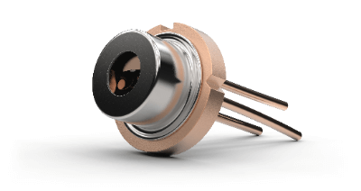
Un diodo láser es una luz que utiliza la emisión por recombinación de un semiconductor.

La emisión por recombinación se produce cuando un electrón y un hueco (agujero) se encuentran en la unión y la energía extra que tienen en común se convierte en luz. La luz de los diodos láser es una luz láser de una sola longitud de onda y alineada en fase, también conocida como láser semiconductor y descrita como LD.

El color de la luz láser de semiconductor viene determinado por los elementos constitutivos del semiconductor. Por ejemplo, el InGaN es de UV a verde (380-540 nm), el AlGaInP es rojo (620-700 nm) y el InGaAsP es IR. Los sustratos respectivos son “GaN” para InGaN, “GaAs” para AlGaInP e “InP” para InGaAsP.

Los LED emiten luz del mismo modo que los láseres semiconductores, pero la fase y el rango de longitudes de onda de la luz son más variados que en los láseres semiconductores. Esto significa que, a diferencia de los LED (diodos emisores de luz), los láseres de semiconductores emiten luz basándose en un principio conocido como “emisión inducida”, que permite emitir luz intensa con una fase bien definida.

Usos de los Diodos Láser

Los diodos láser se utilizan mucho en aparatos de consumo. La razón es su pequeño tamaño y la posibilidad de fabricarlos en serie, lo que reduce los costes de producción.

En equipos informáticos, los diodos láser se utilizan en lectores ópticos para unidades ópticas como CD, DVD y BD, fotocopiadoras, impresoras láser y equipos de comunicación basados en fibra óptica. Las aplicaciones de alta potencia incluyen marcadores láser y máquinas de procesamiento láser.

La naturaleza de la luz láser, resistente a la difusión y de gran alcance, también se ha utilizado en instrumentos de topografía y punteros láser para apuntar a objetos, y se ha generalizado junto con la miniaturización y la reducción de precio de los elementos láser semiconductores rojos de baja potencia.

Principio de los Diodos Láser

En los diodos láser, la luz se emite cuando los huecos (agujeros de electrones) y los electrones se recombinan bajo la aplicación de un voltaje.

El fotón emitido provoca que otro electrón se recombine con el hueco uno tras otro, emitiendo un fotón, de modo que la luz generada tiene la misma fase y longitud de onda. Como la longitud de onda de la luz es siempre constante, se utilizan en situaciones en las que se requiere una cantidad constante de luz, como los lectores de códigos de barras, los punteros láser y las comunicaciones por fibra óptica.

Más Información sobre los Diodos Láser

1. Especificaciones de los Diodos Láser

La curva L/I se utiliza para comprender las especificaciones de los diodos láser. Esta curva permite registrar la corriente de accionamiento suministrada en relación con la intensidad luminosa de salida.

Esta curva se utiliza para determinar el punto de funcionamiento (corriente de accionamiento a la salida de emisión nominal) y la corriente umbral (corriente de arranque del láser) en el láser, y también se utiliza para determinar la corriente necesaria para alcanzar una alta potencia de salida a una corriente determinada.

De la lectura de este diagrama de curvas se desprende que la salida óptica depende en gran medida de la temperatura y que, a medida que ésta aumenta, las características del láser también disminuyen. Esto permite visualizar y estimar la eficiencia del diodo láser mediante la incorporación de la curva L/I.

2. Diferencia entre los Diodos Láser y los Diodos Emisores de Luz

Los diodos emisores de luz se caracterizan porque la luz no está en fase y, por tanto, se difunde radialmente. En cambio, los diodos láser están en fase y, por tanto, producen un haz de luz lineal.

En los diodos emisores de luz, la capa emisora de luz tiene una gran superficie, lo que dificulta la entrada de la luz en una fibra pequeña con un sistema de núcleo pequeño. En cambio, los diodos láser tienen una capa de emisión estrecha, pero inciden fácilmente en fibras ópticas con sistemas de núcleo pequeño.

En los diodos láser, los fotones emitidos se desencadenan por la recombinación de huecos y electrones cuando se aplica una tensión, y otros electrones se recombinan con los huecos uno tras otro para emitir fotones (emisión inducida). La luz producida es, por tanto, de la misma fase y longitud de onda. En cambio, la luz generada por los diodos emisores de luz es de varias fases y longitudes de onda.

3. Vida Útil de los Diodos Láser

La vida media de un diodos láser depende del entorno de funcionamiento (temperatura de funcionamiento, electricidad estática, sobretensiones en el suministro eléctrico) y suele estimarse en 10.000 horas. Entre los factores ambientales que afectan a la esperanza de vida, aquí se analiza la temperatura de funcionamiento.

En primer lugar, el efecto de la temperatura de funcionamiento es que se dice que un aumento de 10°C en la temperatura de funcionamiento reduce la vida a la mitad, y si la temperatura sigue aumentando por encima de la temperatura máxima de funcionamiento, el potencial de daños en el diodo láser y la degradación del rendimiento a largo plazo se hace mayor. Por lo tanto, se recomienda utilizar disipadores de calor (placas radiantes) para disipar el calor del interior del producto hacia el exterior a fin de evitar en la medida de lo posible los efectos de la generación de calor.

カテゴリー
category_usa

Spectral Irradiance Meters

What Is a Spectral Irradiance Meter?

A spectral irradiance meter is an instrument that measures the irradiance of light from a source.

Irradiance refers to the incident radiant flux per unit area, essentially measuring the light energy reaching a given area from a light source. Thus, spectral irradiance meters measure irradiance in units of W/m² (watts per square meter). The required ambient brightness for human activities varies, and it’s not just about having bright surroundings.

The human eye is not suitable for measuring brightness due to its adaptability to surrounding light levels, making an objective evaluation challenging. Hence, the importance of using a spectral irradiance meter for objective quantification of ambient brightness.

Uses of Spectral Irradiance Meter

Spectral irradiance meters are essential in measuring the brightness in various settings, including offices, factories, and museums. They are crucial in environments like laboratories and factories where brightness levels must be strictly controlled, sometimes even regulated by law.

Additionally, regulations such as the Fire Service Law mandate specific illuminance levels for audience guide lights in movie theaters and similar venues, necessitating the use of spectral irradiance meters to ensure compliance.

Principle of Spectral Irradiance Meter

Spectral irradiance meters use elements like photoresistors or photodiodes to detect electromagnetic waves. Photoresistors change their electrical resistance in response to electromagnetic waves, while photodiodes convert these waves into electric current.

Using different elements, such as photodiodes, allows the measurement of both radiant illuminance (including non-visible electromagnetic waves) and visible illuminance. These measurements serve various purposes and are vital in different contexts.

Other Information on Spectral Irradiance Meter

1. Difference Between Spectral Irradiance Meter and Illuminance Meter

An illuminance meter, unlike a spectral irradiance meter, is designed to detect only light within the human-visible wavelength spectrum. Radiant illuminance includes both visible light and electromagnetic waves like ultraviolet and infrared rays, essential in certain environments.

For instance, to measure the effect of ultraviolet rays on chemical substances, which may undergo decomposition, a spectral irradiance meter is indispensable.

2. Difference Between an Irradiance Meter and a Spectral Irradiance Meter

The key distinction lies in their spectral measurement capabilities. An irradiance meter calculates irradiance as a total of the measured wavelength range, whereas a spectral irradiance meter provides detailed output for each wavelength within the range at specific resolutions (e.g., 1 nm increments).

Spectral irradiance meters can also function as irradiance meters and evaluate the color rendering properties of light sources, an important aspect in settings like museums where high color rendering LEDs are increasingly required.

カテゴリー
category_usa

Stirring Tanks

What Is a Stirring Tank?

Stirring Tanks

A stirring tank is a tank used for stirring.

Different solids, liquids, and gases are placed in a stirring tank to stir and mix them. The shape of a stirring tank is indicated by the ratio of the liquid surface height to the tank’s inner diameter. Generally, an efficient ratio is around 1.0 to 1.5.

If the stirring tank is excessively thin, the top and bottom sides of the tank will not be stirred properly and a concentration gradient will easily occur, while if the tank is excessively thick, the tank diameter will increase, requiring a thicker tank.

Uses of Stirring Tanks

Stirring tanks are used as the exterior of an agitator that mixes substances. Depending on the use of the stirring tank, components such as coils, jackets, baffles, and nozzles are installed. When installing components, they must not obstruct the flow of liquid through the agitator and must be structurally strong.

Coils and jackets are used for heating and cooling. Baffles are responsible for imparting vertical flow to the horizontal flow of liquid, and for maximum effectiveness, 2 to 8 baffles should be installed for a tank.

Nozzles are used for injecting and draining liquid in the tank, and when gas is injected into the liquid, it can also be put in through nozzles at the bottom of the tank for bubbling.

Principle of Stirring Tanks

A stirring tank consists of a motor, reduction gear, shaft sealing device, shaft, stirring blades, and baffles.

1. Shaft Sealing Device

The motor rotates and transmits power to the shaft, which, when equipped with a reduction gear, decelerates and increases torque in accordance with the reduction gear. The shaft sealing device will seal the inside of the tank without interfering with rotation. Commonly used shaft sealing devices are gland packings and mechanical seals.

2. Agitation Blades

The shaft rotates at the same time as the agitator blades rotate, enabling the liquid to be agitated. Agitation in the stirring tank is caused by thrust and radial forces depending on the shape of the stirring tank blades. In addition, the liquid in contact with the agitation blades flows vertically and horizontally, resulting in the unique behavior of the agitation blades.

3. Baffling

The agitated liquid can be further dispersed by baffles installed in the tank. Baffles are used to change the flow from laminar to turbulent. Baffles are especially effective when agitating low viscosity liquids, which tend to become laminar.

4. Tank

The shape of the tank changes the degree of liquid dispersion. The shape of the tank bottom has a particularly large effect on liquid accumulation. Commonly used is a 2:1 semi-elliptical or 10% dish shape. If the ratio of the height of the liquid surface to the tank’s inner diameter is 1.2, the tank’s inner diameter can be calculated by multiplying the liquid volume by 1.14 and then multiplying by 1/3.

Other Information on Stirring Tanks

1. Type of Agitating Blade

The part that transmits the rotation of the motor to the stirring tank and agitates the material is the agitating blade. The role of the agitation blade can be broadly divided into two: “shearing action,” which provides shear force to various parts of the stirring tank, and “circulating action,” which provides the formation of a circulating flow. Based on the viscosity of the material to be agitated, an agitation blade with the optimum balance that can achieve the objective is selected.

Typical stirring blades used in stirring tanks are as follows

Propeller Blades
Propeller blades are three-winged agitation blades used on ships. They are not suitable for agitating high-viscosity materials, but are used to prevent sedimentation when individual particles are contained in low-viscosity liquids. Other than that, they are widely used as standard agitation blades due to their cost and compactness.

Disk Turbine Blade
Disk turbine blades are agitator blades consisting of a disk with several blades attached to it. Although they consume a lot of power, they generate a large circulating and shearing action. They can be used for agitation while pulverizing solids, and for agitation with reactions such as gas dispersion and absorption.

Anchor Blade
Anchor blades are agitation blades shaped like a ship’s anchor. Generally, these stirring blades are shaped from the bottom of the stirring tank along the wall. Although they can agitate high-viscosity materials, their agitation capacity is not as high as that of other agitator blades.

2. Types of Stirring Tanks

There are several types of stirring tanks. It is important to select a stirring tank according to the stirring method appropriate for the liquid to be mixed.

Central Agitation
This is a stirring method in which the middle axis of the stirring blade is vertically attached to the center of the stirring tank. This is a common method and is characterized by uniform flow.

Eccentric Inclined Agitation
This is an agitation method in which the stirring blades are installed not in the center of the stirring tank but at an angle to the bottom surface. Even without baffles, turbulent flow can be generated.

Bottom Agitation
This is an agitation method in which the stirring blades are attached from the bottom of the stirring tank. When the stirring tank is large, the attachment of a long shaft becomes unnecessary.

カテゴリー
category_usa

Continuity Checkers

What Is a Continuity Checker?

Continuity Checkers

A continuity checker is a measuring instrument used to verify that electricity is flowing between two electrodes in an electrical circuit.

With a continuity checker, you can quickly determine if there is a problem with the circuit or if the wiring is properly connected. There are a variety of types available, ranging from simple pen-type devices to those with high-precision digital display functions.

Generally, these devices are used by professionals in electrical work. However, they can also be purchased relatively inexpensively at home centers.

Uses of Continuity Checkers

Continuity checkers are inspection instruments used to detect continuity or disconnection of electrical circuits, and are used for the following applications

1. Checking Wiring Connections

Used to verify that wiring connections are correct. By using a continuity checker, it is possible to quickly check if the wiring is connected properly and if there is any disconnection or poor contact.

2. Testing Electronic Circuits

A continuity checker is used to test whether components and circuits in an electronic circuit are properly connected. A continuity checker can be used to determine if components and circuits are functioning properly, for example, if relay contacts are in an ON/OFF state under certain conditions.

3. Checking Electrical Work

During electrical work, a continuity checker can be used to check wire connections and wiring continuity to ensure safe and reliable electrical installations.

4. Troubleshooting Electrical Equipment

A continuity checker can be used to identify malfunctions in electrical equipment. For example, if electrical equipment does not work, a continuity checker can be used to identify problems with the power supply or wiring.

Principle of Continuity Checkers

Typically, continuity checkers use two probes (sharp metal rods) to connect the two ends of an electrical circuit. It has an internal circuit, such as a power supply or oscillator, which transmits signals generated by the circuit to the electrical circuit through the probes.

A continuity checker detects whether the transmitted signal passes through the circuit or not. If it detects the passage of a signal, it displays the result on a display device. Typical indicators include LED lamps and buzzers that light or sound when a signal is detected.

When an electrical circuit is conducting, the continuity checker signal passes because of the current flow. On the other hand, if the electrical circuit is disconnected, the signal will not pass because no current flows. In this way, continuity checkers can detect continuity or disconnection of an electrical circuit.

Types of Continuity Checkers

There are the following types of continuity checkers:

1. Pen-Type Continuity Checker

Shaped like a pen, the pen-type continuity checker checks the continuity of a circuit by placing the pointed probe against the electrode. It is easy to operate and use, and is often used for beginners.

2. Multimeter Type Continuity Checker

This continuity checker is equipped with a digital display and also has measurement functions such as ohmmeter, voltmeter, and ammeter. They are more accurate and can make more precise measurements, but are complicated to operate and not suitable for beginners.

3. Continuity Checker With LED Light

This continuity checker allows the user to check the continuity of a circuit by means of a lighted LED light. It is easy to operate, easy to see, and easy to use.

4. Stylus-Type Continuity Checker

This is a stylus-type continuity checker that checks continuity by touching the probe. Since it can be handled intuitively, it is said to be easier to operate than general pen-type continuity checkers.

カテゴリー
category_usa

Constant Current Drivers

What Is a Constant Current Driver?

A constant current driver is an electronic circuit designed to output a stable current, unaffected by changes in supply voltage, temperature, or load. It achieves this by controlling the collector current of a transistor or the drain current of a MOSFET through the base current and gate voltage.

Various circuit methods are employed, including those using Zener diodes or operational amplifiers, and some utilize switching methods like PWM (Pulse Width Modulation) control.

Applications of Constant Current Drivers

Constant current drivers are primarily used in LED driver circuits, where they are often referred to as LED drivers. Since LED brightness is determined by the current, these drivers help maintain consistent brightness by compensating for power supply voltage fluctuations and temperature changes. This control not only stabilizes LED characteristics but also enhances efficiency and longevity.

Another common application is in motor drive circuits, where they provide a constant current for consistent torque output.

Principles of Constant Current Drivers

One circuit approach involves a Zener diode connected to a transistor’s base, an emitter resistor, and a load connected to the collector. The Zener diode, which is also connected to the power supply via another resistor, ensures a constant voltage at the transistor’s base regardless of supply voltage changes. This setup results in a self-regulating mechanism where any fluctuation in collector current alters the emitter resistor’s voltage drop, thereby adjusting the base current to stabilize the collector current to the load.

In operational amplifier methods, the collector current stabilization is achieved by connecting a Zener diode to the non-inverting input, a transistor’s emitter to the inverting input, and its base to the output.

For the switching method, PWM control is used to maintain an average constant collector current by toggling the transistor on and off.

カテゴリー
category_usa

Paint Agitators

What Is a Paint Agitator?

A paint agitator is a device used to mix paints that tend to settle and separate in containers. They are crucial in preventing composition changes in paints containing special beads or finishing agents, which can affect the final product’s quality.

Without proper agitation, uneven mixing can occur, especially in containers with corners, like 1-ton cans. This unevenness can lead to defects in the finished product, such as “bumps and debris,” if dry film returns to the paint.

Applications of Paint Agitators

Paint agitators are commonly used before applying coatings. Many designs feature rings on the blades to prevent contact with the container walls, ensuring efficient mixing without damaging the container.

Agitation can cause a rise in temperature, altering paint viscosity and impacting workability. It is important to agitate paint considering subsequent use and curing times.

Principles of Paint Agitators

Typically powered by air motors, paint agitators allow for adjustable speed and torque, essential for mixing different paint types. This system is safe for paints containing organic solvents, as it avoids the risk of sparking.

Air motor-driven agitators operate by compressing air inside the motor, generating rotational force through the difference in vane area. This design allows for compact size, efficient air cooling, and continuous use without overheating. Additionally, the lack of oil in the power source prevents oil drips, avoiding paint film defects like “hazing.”

Other Information on Paint Agitators

1. Paint Mixer

Paint agitators, also known as mixers, come in various models. They use motors to rotate mixing blades, efficiently blending paint and other materials. When selecting a paint mixer, consider motor speed, torque, and blade shape, which depend on the paint’s viscosity and the amount being mixed.

Modern mixers often offer variable speeds and torques. For low-viscosity materials like primers, choose high-speed, low-torque mixers. For thicker materials, opt for low-speed, high-torque mixers. Blade size and shape should match the paint type and quantity, ensuring effective and safe mixing.

2. Method of Mixing Paint

When stirring paint with an agitator, proper technique is crucial. Secure the paint container between your feet to prevent movement during agitation. Ensure the agitator’s cord is well-managed to avoid entanglement with the mixing blade, preventing accidents.

カテゴリー
category_usa

Repair Clamps

What Is a Repair Clamp?

A repair clamp is device used to quickly stop leaks in piping systems.

These clamps allow for repairs without emptying the contents of the piping, enabling uninterrupted facility operations. Installation and tightening are straightforward, allowing repair work to be completed in just 5 to 10 minutes.

Besides straight pipes, repair clamps can also seal leaks in various joint types, such as sockets for straight pipes, elbows for angled connections, and T-shaped junctions, similarly to how they work with straight pipes.

Uses of Repair Clamps

Repair clamps are employed to swiftly fix leaks in piping systems without halting the equipment’s operation. They are essential in places like hotels, hospitals, condominiums, and factories where equipment shutdowns due to sudden leaks are not feasible.

They are also used in situations where piping replacement is difficult, or as a temporary solution until replacement is possible.

Note: Repair clamps are specifically for repairs and are not suitable for standard plumbing connections.

Principles of Repair Clamps

Different repair clamps are available depending on the material and shape of the piping needing repair.

For material, there are options for steel, copper, and polyvinyl chloride (PVC) pipes. Steel pipes, including carbon and stainless steel, are versatile and used in various applications such as oil and gas pipelines, water and sewage systems, and building utilities. Copper pipes, known for their sterilization and corrosion resistance, are commonly used in building water systems. PVC pipes, with their low internal resistance and high corrosion resistance, are ideal for ventilation, water supply, and drainage systems.

There are three types of pipe shapes catered for: straight pipe-only, dual-use, and multi-fitting.

The straight pipe-only type is designed solely for straight pipes, available in various lengths to cover small to large leakages.

The dual-use type can repair not only straight pipes but also joints like sockets, elbows, and tees.

The multi-fitting type is versatile, capable of repairing edges of fittings like valves and flanges, which are incompatible with the dual-use type.

Repair clamps are available for various combinations of pipe materials and shapes, such as straight steel, multi-fitting steel, straight copper, and PVC pipes.

カテゴリー
category_usa

Reflectometers

What Is a Reflectometer?

A reflectometer is a device used to check how much light returns to an object when it is illuminated.

The measurement of reflectance is based on the method for measuring reflectance.

Reflectance is very important in car mirrors. Because they become dazzling when the sun reflects off them or when the headlights of a following vehicle hit them, they are equipped with technology that automatically changes the reflectance.

It is also used for other purposes, such as measuring the roughness of plated surfaces.

Uses of Reflectometers

Reflectometers are available in direct and indirect measurement methods.

  • Direct Reflectometry
    This method measures the reflectance when a light source is shone directly on the object to be measured. True reflectance is obtained due to absolute reflection.

This method is used for parts with smooth surfaces, such as car mirrors and plastic products, where specular reflection is likely to occur.

  • Indirect Reflection Method
    This method measures reflectance by shining a light source indirectly on the object to be measured.

The light source is shined onto an integrating sphere. When light strikes the integrating sphere, diffuse reflection is repeated in the sphere, and light of uniform intensity, regardless of position, can be shone on the material.

This method is effective for materials that are uneven or prone to diffuse reflection.

Principles of Reflectometers

The principle of reflectometers is based on the Fresnel equation. Fresnel’s equation takes into account incident light, reflected light, transmitted light, and refractive index.

When light is shone on an object, incident light and reflected light are generated. The angle between the incident light and the center of the object is called the angle of incidence and the angle of reflection, respectively.

Not all incident light becomes reflected light, but some light is transmitted toward the object. If the refractive index of the object differs from that of the medium through which the light passes (air), the angle of transmission between the center of the object and the transmitted light differs from the angle of incidence.

The reflectance can be calculated by applying the difference between the angle of incidence (angle of reflection), the angle of transmission, and the refractive index to the equation.

A typical example of where Fresnel’s formula is used is in optical fiber. An optical fiber has a two-layer structure, with materials having different refractive indices in the inner and outer layers.

If there is no problem on the connecting surface of the layers, reflection does not occur, but if a gap is created due to cutting or other reasons, reflection will be repeated. The degree of reflection is used to determine the extent of the gap.

カテゴリー
category_usa

Optical Converters

What Is an Optical Converter?

An optical converter, also known as an optical media converter, is a device designed to convert electrical signals into optical signals and vice versa.

In communication systems that use metal cables like LAN cables, electrical signals are used to transmit data. However, as the transmission distance increases, these electrical signals can suffer from attenuation and can be susceptible to electromagnetic interference, leading to communication errors.

Optical fiber communication, on the other hand, relies on light pulses to transmit signals. Optical signals in fiber optics have low attenuation and are immune to electromagnetic interference, making them ideal for stable long-distance communication. Optical converters are used to bridge the gap between metal cables and optical fibers in such systems.

Applications of Optical Converters

Optical converters find applications in various scenarios, including connecting optical lines to homes and office LAN systems and linking WiFi communication facilities to national optical networks.

As networks connect computers, peripherals, manufacturing equipment, and household appliances, data communication facilities are essential. Optical fiber, with its advantages of low attenuation, noise immunity, lightweight, and corrosion resistance, is being deployed extensively in communication networks worldwide.

Devices connected to these networks operate using electrical signals, but optical signals transmitted via optical fiber cannot be directly utilized. Optical converters play a crucial role in converting these optical signals into electrical signals for use by connected devices.

Principle of Optical Converter

1. Electrical to Optical (EO) Conversion

EO conversion involves converting electrical signals into optical signals. This is achieved using a semiconductor laser as the light source for the optical signal. Two common laser light modulation methods are direct modulation, where the electrical signal directly drives the semiconductor laser, and external modulation, where the semiconductor laser is continuously driven, and its light is modulated by an external modulator.

While direct modulation is compact and simple in terms of modulation circuitry, it can suffer from waveform degradation due to the semiconductor laser’s direct drive, making it less suitable for long-distance communication. External modulation is preferred for such applications.

2. Optical to Electrical (OE) Conversion

OE conversion involves converting optical signals into electrical signals. This is achieved using a photodiode, which is a semiconductor device also known as an optical sensor. When light strikes the photodiode, it generates electrons and holes in the PN junction, resulting in current flow. The photodiode converts the optical input into an electrical signal.

An Optical converter is a combination of EO and OE converters, allowing bidirectional conversion between electrical and optical signals.

Additional Information on Optical Converters

Circuit Pattern of Optical Converter

Effective utilization of optical converters requires careful design of circuit patterns and mounting layouts.

1. Impedance Matching
In Gbps-class modulation, impedance matching becomes critical, especially when dealing with millimeter-scale circuit lengths. It’s essential to ensure impedance matching between the semiconductor laser and the laser driver. Poor impedance matching can lead to signal reflections and ringing, degrading the modulation waveform. Verification of characteristics through simulation during the design phase is often necessary.

2. Photodetector and First-Stage Amplifier Configuration
A very weak signal flows between the photodetector and the first-stage amplifier. Minimizing noise in this signal path is crucial to meet specified minimum photosensitivity requirements. Since photosensitivity can vary depending on assembly and layout, characteristic verification during mounting is often necessary, in addition to impedance matching considerations.

カテゴリー
category_usa

Positioning Sensors

What Is a Positioning Sensor?

A positioning sensor is a device used to measure and detect the location of objects or individuals. These sensors utilize various technologies to gather location data, offering the ability to detect position and movement with high precision. They can provide real-time object position information, ensuring high accuracy and rapid response.

Non-contact positioning sensors can detect position information without physical contact with the object, allowing for minimal damage or wear to both the object and the sensor equipment.

Applications for Positioning Sensors

Positioning sensors find widespread use in several industries:

1. Robotics and Automation

In robotics, they are used for tasks such as detecting the position and shape of objects via camera systems and image processing. They also control robot arms and are used in part molding lines for automated manufacturing. Rotation detection sensors attached to robot motor shafts aid in precise movement control.

2. Machining

These sensors are crucial in machining for placing machined parts accurately or measuring distances to objects, using encoders to improve positioning accuracy by detecting motor rotation angles.

3. Warehouse Management and Logistics

Used in warehouse management, positioning sensors track inventory location and movement, and control automatic guided vehicles (AGVs).

Principles of Positioning Sensors

Positioning sensors operate on various principles but commonly involve interacting with objects or the environment to detect changes in position. Some measure distance using triangulation or time measurement methods, while others use mechanical feedback devices. They all function by detecting changes in position or movement to gather positional information.

Types of Positioning Sensors

There are several major types of positioning sensors:

1. Limit Switch

Limit switches detect object position through the movement of an actuator, converting this movement into an ON/OFF signal.

2. Photoelectric Sensor

These sensors use light sources and receivers to detect object presence, position, or transparency. Components such as photocells and photodiodes are common in photoelectric sensors.

3. Ultrasonic Sensors

Ultrasonic sensors measure position based on the transmission and reception of ultrasonic waves, commonly used for measuring distances and liquid levels in tanks.

4. Encoder

Encoders, connected to rotating shafts, detect position information of rotational or linear motion. Optical encoders use a patterned rotating disk with a light source and optical detector for high-accuracy position detection.