カテゴリー
category_es

Voltage Generators

What Is a Voltage Generator?
Voltage Generators

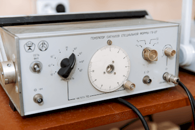
A voltage generator is a generator that generates arbitrary voltages with high precision and output them as needed for various applications.

A common use for voltage generators is to produce specific voltages during the testing phase in research and development.

There are various types of voltage generators available from manufacturers of measuring instruments, and it is important to select the appropriate one based on the operating environment and intended use.

The demand for voltage generators in the field of in-vehicle component development, especially in relation to CASE (Connected, Autonomous, Shared, Electric) compliance, is growing.

Applications of Voltage Generators

Voltage generators are used to extract specific voltages for tests in the development of electronic components for xEVs (extended-range electric vehicles) in support of CASE initiatives.

Currently, voltage generators can be broadly categorized into four types, and it is necessary to choose the type that best fits the purpose and operating environment.

The classifications of voltage generators are as follows:

  • Bipolar output: Outputs across positive polarity without switching.
  • Four-quadrant output (source and sink operation).
  • Linear bipolar output: For AC-DC conversion, outputs across both positive and negative polarity with switching.
  • 2-quadrant output (source and sink operation).

Principles of Voltage Generators

Voltage generators consist of a complex assembly of coils, resonance mechanisms, and control boards. They can generate any desired voltage according to the specified function of the generator.

These generators are capable of high-output and high-voltage analog waveform control with dynamic characteristics. They can operate under positive and negative pole source/sink and bipolar outputs capable of 4-quadrant operation.

Voltage generators play an essential role in the development of CASE-compliant electronic components for xEVs.

Advancements in boost/breakdown technology using materials that combine rare metals are simplifying and downsizing amplification circuits. This technology is expected to have wider applications in the future.

The advantages and disadvantages of voltage generators are as follows:

  • Advantage: High-precision, high-quality arbitrary voltage extraction is possible.
  • Demerit: Special high-voltage level voltage generation requires considerably large equipment.
カテゴリー
category_es

Electromagnetic Flow Meters

What Is an Electromagnetic Flow Meter?

Electromagnetic Flow Meters

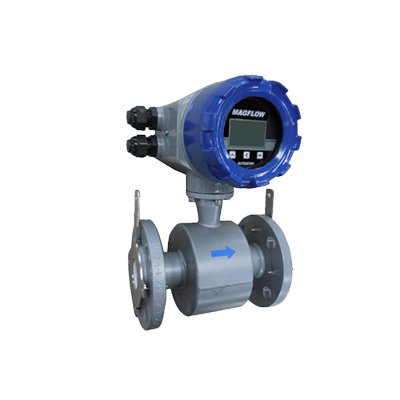
Electromagnetic flow meter is a device that utilizes the principles of electromagnetic induction to measure fluid flow rates.

Electromagnetic flow meters are characterized by the absence of moving parts and the absence of pressure drop in the measurement process. However, due to their operating principle, electromagnetic flow meters are limited to measuring conductive liquids and cannot measure insulating fluids like oils or gases.

When used with conductive liquids, these meters offer precise measurements unaffected by factors such as temperature, pressure, liquid density, viscosity, or conductivity. They are also capable of measuring the flow rates of slurries and corrosive chemicals containing suspended particles.

Applications of Electromagnetic Flow Meters

Electromagnetic flow meters find applications in various industries due to their ability to measure flow rates in challenging conditions. Some of the common applications include:

  • Fluids containing solids, such as sand-water mixtures in civil engineering projects
  • High-viscosity fluids like cement milk and mortar
  • Acidic liquids, including sulfuric acid and hydrochloric acid, in chemical plants
  • Basic liquids such as caustic soda used in scrubbers
  • Pulp liquids and bleaching agents in the paper industry
  • Beverages like fruit juice and wine in the food industry
  • Pharmaceuticals and blood plasma in the medical industry

As mentioned, electromagnetic flowmeters are versatile instruments used across a wide range of fields.

Principles of Electromagnetic Flow Meters

Electromagnetic flow meters operate based on Faraday’s Law of Electromagnetic Induction, which involves the generation of voltage in a conductor moving through a magnetic field.

This phenomenon occurs when a conductive object moves within a magnetic field, generating a voltage proportional to its speed. Electromagnetic flow meters convert this voltage into flow rate data by detecting it.

A typical electromagnetic flowmeter consists of a measuring tube through which the liquid flows, an exciting coil that generates a magnetic field, and a circuit that measures the voltage induced by electromagnetic induction.

When a magnetic field is created perpendicular to the measuring tube, the conductive liquid flowing through the tube intersects the magnetic field perpendicularly, resulting in the generation of a voltage perpendicular to both the measuring tube and the magnetic field. This voltage can be used to determine the liquid flow rate.

How to Select Electromagnetic Flow Meters

The choice of an electromagnetic flow meter depends on the properties of the fluid to be measured and the installation conditions. Here are some key considerations:

1. Separate Type or Integrated Type

Select between a detector/transducer integrated type or a separate type based on the installation location.

2. Measuring Tube

Choose the measuring tube material that matches the type of liquid to be measured. Options typically include rubber and PFA lining materials.

3. Connection Method

Select the appropriate piping connection method, such as wafer or flange, based on ease of installation and removal. Note that ceramic measuring tubes are typically compatible only with wafer connections.

Additionally, choose the bore size of the measuring tube to match the connecting piping.

4. Electrode and Ground Ring Materials

Select electrode and grounding ring materials that are compatible with the fluid being measured to prevent corrosion. Materials like SUS316L are commonly used for general applications, while other materials like hastelloy, tantalum, or platinum iridium may be suitable for specific corrosive fluids.

5. Communication Method

Determine the communication method for the electromagnetic flow meter. Options may include 4-20 mA DC current analog transmission, HART communication, or other proprietary communication methods. Choose the method that aligns with your maintenance and data collection requirements.

カテゴリー
category_es

Power Loggers

What Is a Power Logger?

A power logger is a device designed to measure and record electric power consumption. Power loggers are offered as products by manufacturers of measurement instruments and are equipped with memory to store power data while simultaneously displaying it.

The unit of electric power measurement is typically in kW (kilowatts) or W (watts), and this information is displayed on the device’s interface panel.

Some power loggers provide the option to choose different sampling rates, with some offering high sampling rates, such as up to 100 times per second (100 Hz).

A variety of power logger models are available, and the appropriate instrument should be selected based on the required measurement accuracy.

Uses of Power Loggers

Power loggers are primarily used for the measurement of electric power consumption. Most power loggers are compact and portable, making them convenient for field use in various applications.

Specific examples of their usage include:

  • Verifying proper operation during electrical work trials
  • Maintenance of production equipment
  • Temporary power measurement for industrial machinery management
  • Monitoring power consumption of household electronic equipment
  • Measurement of power in lithium-ion battery packs
  • Battery management systems in electric vehicles

Principles of Power Loggers

Power loggers can be broadly categorized into two types: direct power measurement devices and indirect power measurement devices.

Both types are equipped with an interface panel for real-time data monitoring, displaying power values, typically in kW (kilowatt) or W (watt). In some cases, mW (milliwatt) units are used for precision measurements. Users can configure parameters such as sampling rates and recording formats on this panel. Higher sampling rates allow for finer data resolution, but they may limit the duration of data storage.

Recording media, such as USB flash memory or SD cards, are commonly used. Data is often stored in CSV or TXT file formats. Since analog signals are used for input data, measurement accuracy can be affected by noise. It is essential to implement noise-reduction measures, such as shielding, to enhance measurement precision.

1. Direct Power Measurement Devices

Direct power measurement devices come with a clamp meter for measuring current and an alligator clip cable for measuring voltage. They measure and record power based on current and voltage readings. In the case of a 3-phase power supply, two clamp meters and three alligator cables are used.

For single-phase power measurement, one clamp meter and two alligator cables are typically employed. Most direct power measurement devices can simultaneously record voltage and current along with power data. Some devices can also measure reactive power and power factor simultaneously.

When using direct power measurement devices, the maximum measurable voltage is determined by the device’s specifications. It is essential to confirm this limitation before making a purchase. If measuring high-voltage power is required, it may be necessary to use an instrument transformer to step down the voltage and then multiply the measurement result by the transformer ratio.

2. Indirect Power Measurement Devices

Indirect power measurement devices record power signals that have been converted by power transducers or similar devices. Typically, the input signal is an analog signal, such as 0-5 VDC or 4-20 mA DC. The maximum measurable value is determined by the range of the power transducer.

カテゴリー
category_es

Conductive Sheets

What Is a Conductive Sheet?

A conductive sheet is a thin product made of an electrically conductive material.

Conductive sheets are flexible, thin, and lightweight, adapting to various shapes and curved surfaces. Their conductive properties enable the transmission and connection of electrical signals.

Additionally, conductive sheets may shield against electromagnetic waves, reducing surrounding electromagnetic influences and maintaining signal stability in electronic equipment.

Uses of Conductive Sheets

Conductive sheets have diverse applications, as detailed below:

1. Semiconductor Products

Conductive sheets are integral to semiconductor products, such as touch panel technology, where they detect finger and pen input. They also support LCD backlighting, providing electrical supply and wiring for light-emitting diodes (LEDs).

2. Manufacturing Facilities

In clean rooms of manufacturing plants for electronic substrates and semiconductors, conductive sheets prevent static electricity from damaging semiconductor devices.

3. Research and Development

Widely used in electronics R&D, conductive sheets are crucial in developing new devices, sensors, and flexible electronic devices.

Principle of Conductive Sheets

Conductive sheets feature a structure with uniformly dispersed conductive materials like microscopic particles or fibers, enabling free electron propagation. Common materials include metals like silver and copper, carbon nanotubes, and conductive inks. Some are made from antistatic resin or rubber sheets coated with conductive powder.

For base sheets made of cloth, conductive threads are woven into the fabric. Some products, to maintain flexibility, are laminated with flexible sheets.

Cleaning conductive sheets with detergent can restore their efficacy by removing dust and lowering surface resistance.

Types of Conductive Sheets

Conductive sheets vary in type, as outlined below:

1. Metal Conductive Sheet

Metal conductive sheets, mainly copper and aluminum, connect electrical circuits and contacts. These sheets are durable and withstand high temperatures.

2. Carbon Conductive Sheet

Carbon conductive sheets, made from carbon nanotubes and graphite, are flexible, making them ideal for flexible electronic devices and touch panels.

3. Conductive Ink Conductive Sheet

Conductive ink sheets are created by dispersing conductive particles or polymers in an ink medium. They are used for printing patterned conductive patterns or contacts.

4. Fiber Conductive Sheet

Fiber conductive sheets use metallic or carbon fibers. Their flexibility allows integration into wearable and smart textile products, offering both comfort and conductivity.

カテゴリー
category_es

Internal Grinders

What Is an Internal Grinder?

Internal Grinders

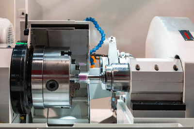
An internal grinder is a machine designed to grind the internal surfaces of primarily cylindrical workpieces.

Grinding is a machining process that utilizes grinding wheels.

Grinding wheels consist of tough abrasive grains, such as aluminum oxide and silicon carbide, bonded together with a bonding agent.

Grinding is not suitable for rough machining due to the shallow depth of cut compared to cutting processes.

However, it is highly effective for precision machining, delivering excellent dimensional accuracy and surface finish roughness.

Uses of Internal Grinders

Internal grinders employ a small-diameter internal grinding wheel attached to a spindle referred to as a wheelhead.

The workpiece is secured using an external jaw chuck or an electromagnetic chuck attached to the spindle.

Internal grinders are broadly categorized into two types based on the grinding method: rotary workpiece type and planetary type.

In the workpiece rotary type, the wheel spindle and the main axis rotate relative to each other, while the grinding wheel on the wheel spindle oscillates back and forth as it cuts into the workpiece mounted on the main axis.

The planetary grinding method is employed when the workpiece is large or challenging to balance during rotation.

While rotating the wheel spindle, the spindle itself is given a planetary motion to grind along the internal surface.

To maintain the sharpness, accuracy, and shape of the grinding wheel, dressing is necessary when changing the wheel or after each grinding cycle.

Grinding wheel dressing involves placing the rotating grinding wheel on the diamond dresser installed on the machine.

Principles of Internal Grinders

In basic workpiece-turned internal grinders, the wheel head with the grinding wheel attached has a sliding mechanism relative to the spindle, allowing the grinding wheel to enter the hole.

Internal grinders are used to grind the internal surface of cylindrical shapes, but by adjusting the slide position, they can also grind the end face perpendicular to the shaft center of the hole.

Simultaneous grinding in a single process enables high-precision machining.

The hole’s diameter and length that can be ground depend on the grinding wheel’s outside diameter and the machine’s stroke.

Various bore diameters can be accommodated by selecting a grinding wheel that matches the bore diameter.

However, as bore deflection tends to be higher due to the wheel spindle’s small size, it is advisable to choose a grinding wheel with the largest possible diameter for the bore and mount it on the wheel spindle head using a short-shafted wheel spindle.

The machine can also handle stepped bore diameters, and coaxiality of the bore diameter can be achieved in a single process, ensuring high precision. Taper grinding can also be performed by angling the spindle.

When grinding workpieces with a grinding wheel, a low peripheral speed can cause abrasive grains to detach along with the bonding agent.

Typically, the wheel spindle head rotates at 2000 to 3000 rpm under standard grinding conditions to achieve the desired peripheral velocity due to the grinding wheel’s small diameter.

The spindle workpiece speed is set to maintain a peripheral speed of about 35 to 45 m/min for the grinding surface.

カテゴリー
category_es

Thermal Flow Meters

What Is a Thermal Flow Meter?

Thermal Flow Meters

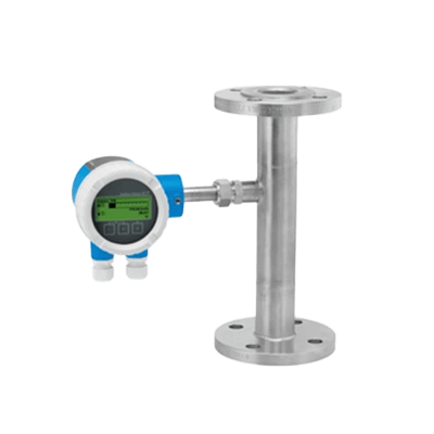
A thermal flow meter is a type of flowmeter that measures the flow rate by using the thermal conduction characteristics of the fluid passing through it.

This device measures flow rate by detecting the temperature difference between the upstream and downstream of the fluid, making it particularly suitable for gas flow measurement. Although there are models for liquid flow measurement, they are typically limited to measuring small flow rates.

Thermal flow meters are sensitive to contamination, hence they are best used for measuring pure gases. They are known for their accuracy in flow rate measurement and can be applied to viscous fluids and high-temperature fluids. However, accurate measurement requires calibration and compensation due to the fluid’s thermal conductivity characteristics and temperature fluctuations. Some fluids may also exhibit slow temperature changes, affecting the response time of the meter.

Flowmeters can be categorized into two types: those measuring volume and those measuring mass. Most measure volumetric flow, but thermal flow meters are capable of measuring mass flow, which is more accurate for gases as their volume changes with temperature and pressure.

Uses of Thermal Flow Meters

Thermal flow meters are utilized in various industries for applications that require accurate gas flow measurement. Their high measurement accuracy makes them ideal for monitoring and controlling industrial processes. In chemical and semiconductor manufacturing, precise flow measurement is crucial for process stability and efficiency.

These meters are also commonly used for energy measurement, such as in heat exchangers and boilers, where they measure calorific values to monitor energy usage and enhance efficiency.

Additional applications include medical anesthesia gas flow measurement and carbon dioxide gas measurement in soft drink production and cooling systems.

Principle of Thermal Flow Meters

Thermal flow meters operate by leveraging the thermal conduction characteristics of fluids. Thermal conduction, the transfer of thermal energy through a temperature gradient, is directly proportional to the flow rate of the fluid. A faster flow rate results in quicker heat transport and a smaller temperature gradient, while a slower flow rate leads to a larger gradient.

These meters estimate the flow rate by measuring the temperature difference in the fluid, using temperature sensors placed before and after the fluid flow.

Construction of Thermal Flow Meters

A thermal flow meter typically consists of piping, a heat source, and thermometers.

1. Piping

Piping serves as the conduit for fluid flow, with the thermal flow meter mounted directly onto it. The fluid flows through the pipe, where its flow rate is measured.

2. Heat Source

The heat source, often an electric heating wire or heater, provides thermal energy to the fluid, creating a temperature difference within the piping.

3. Thermometer

Thermometers, mounted on the piping, measure the fluid’s temperature. They are strategically placed before and after the heat source to detect the temperature differences in the fluid.

Types of Thermal Flow Meters

Thermal flow meters are generally classified into two types based on their flow rate determination method: the temperature difference measurement method and the power consumption measurement method.

1. Temperature Difference Measurement Method

This method measures the temperature difference between the upstream and downstream sides of the heater. It is a cost-effective and simple configuration, often used for measuring small amounts of fluid.

2. Power Consumption Measurement Method

The power consumption measurement method maintains a constant temperature difference by adjusting the heat source’s power. The mass flow rate is calculated based on the power consumption required to keep the temperature difference constant.

カテゴリー
category_es

Dispersers

What Is a Disperser?

A disperser is a device used for dispersing a target substance in a liquid or gas.

In liquid dispersers, dispersion is achieved through varying speeds, collision with beads or agitator blades, or by employing ultrasonic waves.

Airborne dispersers include ejector-type dispersers, venturi-type dispersers, orifices, and more. These devices disperse target substances into gas by breaking down their agglomerates.

Uses of Dispersers

Dispersers find applications in a wide range of fields, including inks, paints, chemicals, electronic materials, and food products.

The production of inks and paints serves as a typical example of disperser usage. Pigments, the primary raw materials in these products, are often dried and agglomerated, necessitating dispersion in a solvent during the manufacturing process.

Particle size, particle size distribution, and particle shape significantly influence the performance of pigments.

Principles of Dispersers

Dispersers employ various dispersion methods depending on the type of equipment used. Shearing action and impact/collision action are the fundamental principles behind dispersion.

In high-speed rotary shear agitators, colloid mills, or roll mills, intense shear stress occurs within the gap between the rotor and the outer casing. Aggregates of particles or the particles themselves are made finer and dispersed due to this shear stress. Increasing shear speed and the solvent’s viscosity can enhance the generated shear stress.

In agitator tanks, vessel-driven mills, and media stirred mills, impact and collision actions are primarily used. Increasing the agitation speed or the use of a medium can amplify the impact.

カテゴリー
category_es

Powder Pumps

What Is a Powder Pump?

A powder pump is utilized for the transportation of powders by mixing them with air, allowing them to behave like a fluid.

In essence, a diaphragm pump is employed for conveying by altering the volume within a container through the movement of a membrane known as a diaphragm, actuated by a piston.

Certain products are designed to minimize dust generation by reducing the volume of air used and by achieving consistent flow rates with minimal pulsation.

Apart from diaphragm pumps, there are also products transported using blowers and vacuum pumps.

Applications of Powder Pumps

Powder pumps find applications across a broad spectrum of industries, including food processing plants, chemical facilities, and water purification plants.

When selecting a powder pump, it is imperative to consider factors such as compatibility with the quantity of material to be transported, the type of powder, flow rates, pulsation levels, dust control measures, size, and power consumption.

Due to the nature of handling powders, substantial maintenance is often required, making ease of maintenance an important consideration.

Here are some examples of powder pump users:

  • Conveying flour and other powdered materials in food factories
  • Conveying powdered water purification materials in water treatment facilities
  • Conveying powdered raw materials in chemical plants

Principles of Powder Pumps

The following is an explanation of the operating principle of powder pumps, using a diaphragm pump as an example.

Powder pumps comprise of a suction port, a diaphragm pump, and a discharge port. A diaphragm pump consists of a container, one or two diaphragms, a piston that displaces the diaphragm outside the container, and a valve.

In operation, when the diaphragm pump expands the container with the outlet-side valve closed, the internal pressure decreases, allowing powder to be drawn in from the inlet side. Subsequently, when the inlet-side valve is closed and the diaphragm pump contracts the container, the internal pressure increases. Upon opening the outlet-side valve, the powder is blown out from the outlet and transported. Using two diaphragms connected to both ends of the piston is common practice, as it enables efficient powder transport within a single reciprocating cycle.

カテゴリー
category_es

Velocity Sensors

What Is a Velocity Sensor?

A velocity sensor is used to measure the velocity of a liquid in a factory production line or a river.

A wide range of methods have been developed to measure flow velocity, such as measuring the momentum of fluid rotating an impeller, measuring the phase shift of ultrasonic waves caused by flow velocity, and measuring the amount of heat lost by the fluid.

Uses of Velocity Sensors

Velocity sensors are widely used in factories, environmental facilities, and residential facilities.

When selecting a flow sensor, consider whether the operating principle to be used does not affect the flow of the fluid, the range of flow velocity that can be measured, durability according to the temperature and type of flowing fluid, and ease of maintenance.

The following are examples of velocity sensors in use:

  • Measuring flow velocity for river ecosystem studies
  • Measurement of flow velocity of exhaust gas flowing through factory ducts
  • Adjustment and control of flow velocity of chemical solutions

Principles of Velocity Sensors

The measurement principles of velocity sensors are divided into impeller type, ultrasonic type, and thermal type.

  • Impeller Type
    The impeller type consists of an impeller with a magnet attached, a coil to read changes in the magnetic field of the magnet, and a weight to direct the impeller in the direction of fluid flow. During operation, the impeller is rotated by the fluid flow, and the amount of rotation is transmitted by measuring the change in the magnetic field of the magnet attached to the impeller with a coil or the like and transmitting an electrical signal.
  • Ultrasonic Type
    The ultrasonic type consists of an ultrasonic generator and receiver. The flow velocity is measured by the Doppler effect, which irradiates ultrasonic waves toward a flowing fluid and measures the amount of change in the phase of the ultrasonic waves bounced back by the fluid. It is characterized by non-contact measurement.
  • Thermal Type
    The thermal type consists of a detection element that detects heat, such as a thermopile, and an amplifier. During operation, the temperature of the measuring section decreases due to fluid flow, and the flow velocity is calculated by measuring the amount of decrease. It is characterized by the fact that it is not easily affected by the type of fluid.
カテゴリー
category_es

Voltage Converters

What Is a Voltage Converter?

A voltage converter is a device that transforms the voltage of an electrical power source to a desired level, making it suitable for use with different electronic devices and appliances. It is particularly essential when the power supply voltage differs between regions or countries, enabling the continuous operation of equipment in various power environments.

It’s important to choose a voltage converter with adequate capacity to ensure stability and safety, especially when dealing with high-powered devices.

Uses of Voltage Converters

Voltage converters have diverse applications, including:

1. International Travel and Business Trips

They are commonly used in international travel and business to adapt electronic devices to local voltage standards, ensuring their proper functioning.

2. Industry

In industrial settings, voltage converters are used to power machines and equipment that require different voltages. They also integrate power from renewable energy sources and generators into industrial applications.

3. Protection of Electronic Equipment

Voltage converters safeguard electronic equipment by ensuring they receive power within the correct voltage range, preventing potential damage due to voltage fluctuations.

Principles of Voltage Converters

The main principles behind voltage converters include Power Conversion and Isolation:

1. Power Conversion

Converters transform the characteristics of input voltage to produce the required output voltage and power, focusing on efficiency and stability.

2. Isolation

Many voltage converters provide electrical isolation between input and output, enhancing safety and protecting against voltage and noise interference.

Types of Voltage Converters

There are two primary types of voltage converters:

1. Transformer Type

Uses coils and an iron core to convert voltage. The transformer’s turn ratio determines the input-to-output voltage ratio. Suitable for alternating current, it provides voltage adjustment and electrical insulation.

2. Switching Power Supply Type

Employs high-frequency switching devices like transistors or MOSFETs to control input power. This type can freely convert frequency and voltage and is used in AC-DC conversion, inverters, and power conditioners for solar power generation.

Voltage converters are fundamental in ensuring that electronic devices operate correctly and safely in different power environments, making them indispensable in globalized and industrial contexts.