カテゴリー
category_usa

Density Meters

What Is a Density Meter?

Density Meters

A density meter is a device that measures the density of a liquid or solid. Density is a value that varies depending on the sample concentration and the type of solvent, and density measurement is used in a variety of industries. Density measurement methods include vibrating densimeters for liquids and pycnometers for solids.

Density measurements are highly repeatable and can be made to 3-5 decimal places (g/cm3). Hand-held density meters are also available, which are less accurate than regular bench-top density meters, but are highly portable and can be used to make digital measurements on site. There are also process density meters (online density meters) that are attached to pipes and continuously measure liquid density.

Measuring Density With a Density Meter

Density meters are used in various industries to measure the density of binary liquid mixtures because density values are closely related to concentration.

For example, a prescribed analytical method for measuring alcohol concentration stipulates the use of a density meter. In addition to ethanol, the density meter can also be used for IPA, hydrochloric acid, sulfuric acid, sodium hydroxide, acetone, NMP, gasoline, diesel fuel, lubricating oil, refrigerants, beer, sugar (Brix), etc., making it suitable for use in any industry, including chemical, petroleum, food, beverage, semiconductor, battery, and automobile.

There are also density meters that can be used to measure not only liquid density but also solid density such as slurry, but it is necessary to confirm that the device is compatible.

Principle of Liquid Density Measurement

The measurement method of digital density meters for liquids is standardized, this method is also registered by ASTM, DIN, etc. as an oscillating density measurement method using a U-tube.

It should be noted that some density meters use this method, while others use their method to correlate with the values of vibrating densimeters.

Density measurement is also possible with Coriolis mass flowmeters, but since these are different from vibrational density meters, it is necessary to select the appropriate device for the purpose in advance.

Solid Density Measurement

Solid density measurement is used in research, development, and quality control efforts in a variety of industries. One of these techniques is used as an internationally recognized test method. Many of the standard test methods described for solid density measurement were created around these instruments.

These test methods are used in all industries today. Tap density meters, gas pycnometers, and other methods should be selected to suit the purpose. It is also necessary to check for compliance with many measurement methods, such as ASTM, ISO, UOP, USP, MPIF, and JIS.

Simultaneous Measurement With Other Physical Property Values

Density values are so common that they are measured in many fields, and in such cases, they are measured simultaneously with other physical properties.

In a liquid density meter, for example, a sample is injected into a U-tube inside the instrument. By introducing the sample from the density meter into a refractometer or similar instrument, multiple items can be measured in a short period. Not only does it work well in laboratories where efficiency is required, but it can also perform complex analyses by using multiple parameters.

This includes a three-component analysis and calculation of volumetric modulus. This can be done with a bench-top density meter or a process density meter.

Points to Keep In Mind When Making Measurements

Density measurement is performed with a fixed amount of sample in the device, so if bubbles or impurities are present, they will be included in the measurement. In the case of liquids and slurries, air bubbles must be removed without fail.

カテゴリー
category_usa

Stereo Microscopes

What Is a Stereo Microscope?

Stereo Microscopes

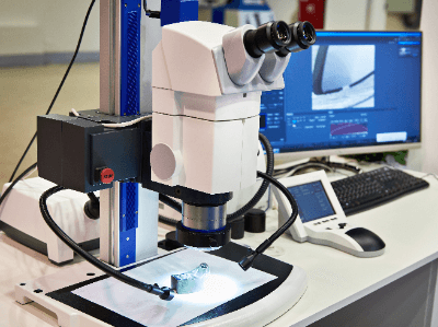
A stereo microscope is a type of optical microscope, also called a binocular stereo microscope. An optical microscope is an optical instrument in which the actual image of a microscopic object magnified by an objective lens is further magnified by an eyepiece lens for observation. Stereo microscopes have two light paths, and by using the parallax between the left and right eyes, objects can be observed in three dimensions. In general, the magnification is relatively low, ranging from several times to 40 times, but the long distance between the objective lens and the stage makes it possible to observe relatively large specimens as they are. In addition, dissection, assembly, and other operations can be performed while viewing the magnified image.

Types and Features of Optical Microscopes

There are various types of optical microscopes depending on the principle of and purpose for which they are used. They are generally classified into two types: biological microscopes and stereo microscopes. Biological microscopes are a type of transmission microscope and should be considered the most common type of microscope. This type of microscope observes a sample by making a thin slide of the sample and allowing light to pass through it.

Stereo microscopes, on the other hand, use both transmitted and oblique illumination. Stereo microscopes have two eyepieces that allow simultaneous observation with both eyes, making it possible to observe the specimen in three dimensions. In addition, the long distance between the eyepieces and the stage on which the specimen is placed makes it suitable for tasks such as dissecting a biological specimen while observing it.

How to Use a Stereo Microscope

The general instructions for using a stereo microscope are as follows.

  1. Set the light source as necessary.
  2. Place the specimen on the stage.
  3. Adjust the eyepiece to fit the width of the eye so that the fields of view overlap into one.
  4. Focus the sample by looking through the right eyepiece with the right eye and operating the focusing device.
  5. While looking through the left eyepiece with the left eye, adjust the diopter adjustment ring to bring the sample into precise focus.

Uses of Stereo Microscopes

In the biological field, stereomicroscopes are used for observation and dissection of animals and plants, such as insects and flowers. They are also used as science teaching materials in educational settings. In the medical field, they are used for dissection and cell manipulation. The microscopes used in neurosurgery and ophthalmology during surgery are also stereo microscopes. In the fields of mechanical engineering, precision machinery, and electronics, microscopes are used for assembly and inspection. Stereo microscopes are also used in a wide range of other applications, such as in dental work, handicrafts, soldering, and other precision work, as well as in the observation and study of old coins and jewelry.

Principle of Stereo Microscopes

There are two types of lenses: “positive lenses” (convex lenses) and “negative lenses” (concave lenses). Positive lenses are used in microscopes.

The center of a positive lens is thicker than its edges, and it refracts light parallel to a line (optical axis) perpendicular to the lens through the center of the lens surface and collects it at a point on the optical axis. This point is called the “focal point.”

A positive lens has one focal point at the front and one at the rear of the lens (front focal point and rear focal point), and the distance between the focal point and the center of the lens is called the “focal length”. The focal lengths of the front and rear foci are equal. The real image formed by the lens when an object is farther from the front focal point of the positive lens is called the “real image” and the image formed when the object is closer to the front focal point is called the “false image.” The real image is an inverted image with the vertical and horizontal sides reversed, while the imaginary image is an upright image.

A typical biological microscope is a device that combines two positive lenses to magnify an object. This device observes the real image formed by the objective lens (lens close to the object) and the imaginary image further magnified by the eyepiece lens (lens close to the eye), so the observed image is inverted.

Stereo microscopes, on the other hand, have an upright prism built into the body, so the observed image is upright. This allows the sample to be observed as it is and enables precise work under the microscope.

Features and Types of Stereo Microscopes

Stereo microscopes are available in a variety of models with different specifications, which should be selected according to the use of the microscope. The following differences, for example, are important points to consider when selecting a microscope.

Difference in Optical System

Stereo microscopes are broadly classified into two types: Galilean parallel optics and Grineau optics. Microscopes with Galilean parallel optics consist of a single objective lens with a parallel optical axis from the eyepiece to the objective lens. Since the optical axis is designed to be parallel, it is possible to add various functions by inserting another unit in the middle.

In addition, since they converge light on a single objective lens, observation at high magnification is possible. Accuracy is easily maintained even when the zoom is increased, and there is a high degree of freedom in the combination of objective lenses. On the other hand, microscopes with Grineau-type optics are designed so that the optical path and optical axis from the eyepiece to the objective lens are all independent of left and right at a certain angle. This is a feature that makes it easy to obtain a three-dimensional image and to design a compact microscope body. However, since there is no parallel part of the optical path, it is not suitable for adding another function to the middle part of the optical path or for setting a large zoom range, as is the case with Galilean lenses.

Difference in Illumination

In stereo microscopes, the choice of illumination is also important for optimum observation of the specimen. Illumination should be selected to match the microscope used and the purpose of the observation. Types of illumination include ring light for bright and uniform illumination, near vertical illumination for fewer shadows, and coaxial illumination for observation of flat specimens with high light reflectance. Halogen lamps and LEDs are generally used as light sources.

Magnification of Stereo Microscopes

There are three types of microscope magnifications: objective magnification, total magnification, and monitor magnification. Objective magnification refers to the magnification of the objective lens alone. Total magnification is the product of the magnification of the objective lens and the magnification of the eyepiece. In a microscope, the image obtained by the objective lens is magnified by the eyepiece, so even if the image has the same overall magnification, the higher magnification of the objective lens has a higher resolution and enables the determination of finer points. Monitor magnification refers to the magnification of an image when it is displayed on a monitor display and indicates how many times larger the image appears when projected on a monitor. The same magnification number can be viewed differently depending on what the magnification represents.

カテゴリー
category_usa

Safety Valves

What Is a Safety Valve?

Safety Valves

Safety valves are installed at the outlet of tanks holding large pressures or positive displacement compressors, such as reciprocating compressors. Safety valves automatically open an internal valve to relieve pressure in the process before an abnormally high pressure builds up in the process that could exceed the design pressure of the tank, or before the compressor is about to break down.

This keeps the process safe. For this reason, they are used in many factories and chemical plants.

Uses of Safety Valves

Safety valves are used to release pressure when the process pressure reaches an abnormal value. For example, in high-pressure tanks, the pressure is constantly monitored and the equipment is shut down before it reaches a dangerous pressure, but safety valves are installed in case of an emergency.

There are also facilities where safety valves must be installed by law. Similarly, they may be installed at the outlet of compressors. In this case, a safety valve is installed to relieve the load on the compressor if the pressure becomes too high.

Principle of Safety Valves

The principle of a safety valve is very simple: a spring holds down the valve plug. By changing this spring, the pressure at which the safety valve starts blowing can be changed.

Some types of safety valves can be adjusted, like pressure reducing valves. However, once a safety valve is blown, it must be replaced because it may continue to blow without being tightened firmly and the pressure at the beginning of blowing may change.

In addition, as a general rule, safety valves should not be opened, so the pressure at the beginning of a blow may be checked once a year during a periodic inspection. One of the most common malfunctions is that when the valve is slightly opened, foreign objects may get caught in the valve and damage the valve plug, or the valve may not be tightened properly and continue to blow. In such cases, it is necessary to clean the valve plug or replace it with a new one to ensure safety.

The outlet of a safety valve must be installed in a safe place to prevent the blowing out of a large amount of gas or other substances under high pressure.

Difference Between Safety Valves and Relief Valves

Safety valves and relief valves are classified into two types according to their function.

Safety valves open fully instantly to release pressure when the set pressure is reached. In a relief valve, the valve plug starts to open when the set pressure is reached, and the degree of opening increases as the pressure rises.

Safety valves are used with steam or gases, and their purpose is to prevent accidents by opening as soon as a dangerous pressure is reached. Relief valves are used with liquids to regulate pressure and prevent pressure buildup due to malfunction.

There are also “pump relief valves,” which are installed at the outlet of the pump and can be used to adjust pressure, prevent pressure buildup due to deadline operation, and provide continuous relief. There are also “safety relief valves,” which have both safety valve and relief valve functions and can be used for both gases and liquids, to be selected according to the use and operating environment.

Selection of Safety Valves

In selecting a safety valve, size and function should be selected as required.

Generally, the size should be one or two sizes smaller than the inlet side pressure reducing valve. The blowout volume should be about 10% of the maximum flow rate of the pressure reducing valve. The set pressure should be slightly higher than the pressure reducing valve pressure. The standard pressure is given in the technical data of each manufacturer.

Next, select the lift method. There are “lift type” and “full volume type,” which are selected according to the application. The full-volume type has 4 to 5 times the blowout volume of the lift type for the same size and is used to relieve hazardous pressure. The full-capacity type is four to five times larger than the Cheng type for the same size blowout volume and is used to relieve dangerous pressure. The Cheng type is often used for pressure adjustment.

In addition, the presence or absence of a lever for checking operation and the type of cap can be selected to suit the use and the environment in which they will be used. With a lever, the operation can be checked at 75% of the set pressure to ensure that there are no abnormalities, such as sticking.

In selecting the cap, the open type releases the blown fluid to the surrounding environment, while the sealed type does not. Select the sealed type if the fluid is dangerous to blow out to the surroundings or if the environment does not allow the fluid to blow out to the surroundings.

Also, the mounting location should be determined so that the mounting posture is vertical since mounting in a sideway or inverted orientation can cause malfunctions.

カテゴリー
category_usa

Modulator

What Is a Modulator?

A modulator is a device that alters the properties (amplitude, frequency, phase, etc.) of an electrical signal, making it easier to transmit. It is essential in wireless communication for encoding data onto a radio frequency sine wave. Modulators can be classified into two types: analog and digital, each handling either analog or digital signals respectively.

Uses of Modulators

Modulators are vital in:

  • Television and radio broadcasts for transmitting audio and video data.
  • Internet connections, where electrical signals are modulated into optical signals for fiber-optic lines or specific frequency telephone lines.

Principle of Modulator

Modulators work by preparing a base signal (carrier wave) and modifying it to carry data. The key modulation methods include:

1. Amplitude Modulation (AM)

Modulates the amplitude of the carrier wave and is susceptible to external noise.

2. Frequency Modulation (FM)

Alters the frequency of the carrier wave, offering less disturbance and wider frequency bandwidth.

3. Phase Modulation (PhM)

Shifts the phase of the carrier wave, commonly used in digital modulation. This method creates a time difference from the original carrier to create a modulated waveform by varying the timing of the carrier signal in proportion to the voltage level of the analog signal.

Types of Modulators

Modulators are classified based on modulation methods into:

1. Analog Modulation Method

Uses AM or FM for applications like radio broadcasting and aviation radio.

2. Digital Modulation

Transmits binary signals, utilized in cellular phones and BS TV broadcasting, with modulation schemes like ASK (Amplitude Shift Keying), FSK (Frequency Shift Keying), and PSK (Phase Shift Keying).

They are called by the above names because they are synonymous with switching carriers.

3. Other Modulation Methods

Includes pulse modulation and spread spectrum, the latter spreading signal energy over a wide band.

Modulators are crucial for efficient and reliable transmission of data in various communication and broadcasting systems.

カテゴリー
category_usa

Chlorine Analyzers

What Is a Chlorine Analyzer?

A chlorine analyzer is a measuring instrument mainly used to measure residual chlorine.

They are also called Residual Chlorine Analyzers. Products that easily measure chlorine concentration using a color chart may also be included in these products.

Chlorine Analyzers are used in a wide range of situations, such as measuring residual chlorine in tap water and swimming pools.

Uses of Chlorine Analyzers

The range and accuracy of the chlorine concentration to be measured differs for each application. It is important to use a Chlorine Analyzer that can measure the chlorine concentration to be measured with sufficient accuracy.

The main applications of Chlorine Analyzers are as follows:

  • To measure whether the residual chlorine concentration in tap water complies with the Water Supply Law
  • To control the concentration of water used for washing vegetables, fruits, eggs, etc.
  • To measure whether the chlorine concentration in swimming pools complies with hygiene standards
  • To measure the chlorine concentration used for sterilization and disinfection in various places, such as industrial equipment and cooling towers, and to control factory water
  • To manage sanitation in welfare facilities, kitchens, and food service facilities
  • When measuring chlorine concentration as a measure against Legionella bacteria in public bathhouses
  • To measure whether the residual chlorine concentration in septic tanks meets the requirements
  • For measuring residual chlorine concentration in cooling water returned to the ocean at nuclear power plants and thermal power plants

Principle of Chlorine Analyzers

Chlorine Analyzer principles include the diethyl-paraphenylenediamine method (DPD method), absorbance spectrophotometry, and polarograph (current) method.

1. Diethyl-Paraphenylenediamine Method (Dpd Method)

The diethyl-paraphenylenediamine method (DPD method) is a method to measure chlorine by colorimetric determination using the chemical reaction of DPD. This method is also an official method stipulated by law.

When DPD (diethyl paraphenylenediamine) is oxidized by chlorine, it reacts with unreacted DPD after passing through colorless quinonediimine to produce N, N-diethyl-semiquinone intermediate, which turns pink-red. Based on this principle, it is possible to determine the concentration of residual chlorine by comparing the color concentration in the colorimeter tube with a standard residual chlorine colorimetric series.

DPD reacts immediately with free residual chlorine but reacts slowly with bound residual chlorine. To determine the concentration of total residual chlorine, which is the sum of free and bound residual chlorine, it is necessary to change the bound form to the free form by adding potassium iodide.

2. Absorbance Spectrophotometric Method

The absorbance spectrophotometric method is a mechanical reading method using absorbance spectrophotometry instead of colorimetric determination in the DPD method. It is usually displayed numerically on a digital display or other means.

3. Polarograph (Current) Method

When two electrodes are placed in a sample and voltage is applied, an electric current flows between the electrodes. The amount of current flowing varies depending on the concentration of residual chlorine. The polarograph method measures the chlorine concentration in a sample by measuring the amount of this current.

Chlorine Analyzers for power plants that measure residual chlorine in seawater use the polarograph method and are large. It is also capable of detecting extremely low concentrations in the range of 0 to 100 ppb.

Types of Chlorine Analyzers

Chlorine Analyzers can be classified into colorimetric (DPD), spectrophotometric, and polarographic (current) types, depending on the measurement principle described above, The detailed measurement principle differs depending on the product.

Generally, colorimetric instruments are small and easy to use. Some absorbance spectrophotometric analyzers are also small and portable. Products such as instruments that can measure residual chlorine in tap water and swimming pools without reagents, instruments that can also measure hypochlorite concentration, and instruments that measure high concentrations have their characteristics, and it is necessary to select the right one for the application.

Depending on the measurement range and resolution (measurement performance), there are many products available from various companies, ranging from high-performance/high-priced ones to simple performance/low-priced ones.

カテゴリー
category_usa

Coating Machinery

What Is Coating Machinery?

Coating machinery is used to coat objects by spraying them with a mist of paint. They are used in automobile and other manufacturing plants, as well as at construction sites. Various principles of coating methods have been developed, including the airless type, which applies direct pressure to the paint and sprays it out in atomized form. The compressor type simultaneously sprays out high-pressure air from a compressor and paint, and the electrostatic type applies voltage to electrodes and sprays paint in an atomized form.

Uses of Coating Machinery

Coating machinery is used in production plants for automobiles, home appliances, electronic equipment, etc., construction sites, and manufacturing plants for airplanes, ships, etc. Coating machinery and dryers are used in factories to apply the coating on the production line automatically. Coating machinery with portable compressors and other equipment is used at construction sites and in the manufacturing process of large machines. When selecting coating machinery, it is necessary to consider the accuracy of the coating, how quickly the coated area dries, the speed of the coating, the size of the coating machinery, and the ease of operation.

Principle of Coating Machinery

The following is a description of the operating principles of coating machinery, divided into airless, compressor, and electrostatic types.

  • Airless Type
    The airless type consists of a tank for storing paint, a diaphragm or centrifugal machine for applying pressure to the tank, and a blow-off head. During operation, pressure is applied to the tank that stores the paint, the paint moves from the tank to the spray head, and the paint is sprayed at high speed so that it spreads from the tip of the head. Since no air is used, the coating speed is high.
  • Compressor Type
    The compressor type consists of a compressor, a tank of paint, and a spraying head. During operation, the high-speed air from the compressor collides with the paint in the head and sprays it out in atomized form. This is the most common and widely used portable type of coating machinery.
  • Electrostatic Type
    The electrostatic type consists of a compressor, a pressure tank containing paint, and a spray head with electrodes attached. In operation, by applying voltage to the electrodes, the paint that comes out under pressure is transformed into a mist by electrical force and ejected from the blowout head. It is characterized by its ability to apply paint with high precision.
カテゴリー
category_usa

Pressure Pumps

What Is a Pressure Pump?

Pressure pumps are utilized to draw in liquids or gases and transfer them to the desired location. Due to their capacity to forcefully transfer liquids and gases, these pumps are employed when there is no difference in elevation, when pumping from low to high, or when high-speed transfer is required.

All pumps operate based on the pressure difference between the suction and discharge ports, and from this perspective, all pumps can be categorized as “pressure pumps.” However, it is commonly used as a general term for pumps employed in toilet drainage, sewage systems, pile erection work, and tunneling sites.

Uses of Pressure Pumps

Pumps used for the following applications are generally referred to as pressure pumps:

  • Household toilet drainage systems
  • Transfer of water and sewage between water supply and drainage tanks in high-rise buildings
  • Discharge of excavated soil containing toxic gases at excavation sites
  • Pumping muddy water during pile erection work
  • Driving filtration equipment at sewage treatment facilities
  • Lifting sand during dredging work
  • Special type fuel injection equipment
  • Submersible throw-in pumps
  • Material transfer systems in food processing plants
  • Oil supply systems
  • Water supply systems using wells

Principle of Pressure Pumps

The fundamental operating principle of pumps is generally consistent: liquids and gases are moved by alternately suctioning and discharging a pump using various mechanisms to create a pressure differential within the pump. From this perspective, all pumps can be categorized as pressure pumps.

Based on their structural characteristics, pumps can be categorized into two primary types: those that rotate a turbine inside the pump at high speed and those that alter the pressure within a compartment located inside the pump.

The first type is referred to as a non-volumetric pump and can pump a relatively large volume of liquid at low pressure. However, depending on the nature of the liquid, accurately setting flow velocity and other parameters may be challenging.

The second type of pump is known as a positive displacement pump, which can maintain high suction and discharge pressures and precisely set flow rates but does not handle large volumes of liquid.

Today, the term “pressure pump” is commonly used as a general term for pumps employed in various systems and work processes, rather than denoting a specific type of pump.

カテゴリー
category_usa

Crimp-Type Connectors

What Is a Crimp-Type Connector?

Crimp-type connectors are components used for connecting conductors, such as wires to printed circuit boards. They consist of a terminal and connector housing, and the connection is made by crimping to sandwich the conductor between them. This method is quicker and more reliable than soldering and is mechanically strong, making it suitable for high-temperature environments and resistant to vibration and shock.

These connectors are available in various types to suit different wire thicknesses and applications, including terminal block-type crimp terminals, splice crimp terminals, and connectors for printed circuit board connections.

Uses of Crimp-Type Connectors

Crimp-type connectors are widely used in:

  • The automotive industry for connecting electronic devices in vehicles.
  • Home appliances like washing machines, refrigerators, and televisions.
  • Telecommunication equipment, including routers, switches, and servers.
  • Industrial equipment such as robots and production line control devices.
  • Renewable energy systems like solar panels and wind power generators.
  • Medical equipment with complex electronic circuits and sensors.

Principle of Crimp Type Connectors

Crimp-type connectors work by physically joining wire strands and brass terminals through plastic deformation under high pressure, creating a mechanical bond without specific metal atom bonding. This process results in stable contact resistance and enhanced crimp strength.

Types of Crimp-Type Connectors

Various types of crimp-type connectors are designed for specific applications:

  • Round crimp terminals for bolt and nut attachments.
  • Y-type crimp terminals with bifurcated connections for easy removal.
  • Bar-type crimp terminals for insertion or plug-in connections.
  • Crimp terminals with insulation sheaths for environmental protection and safety, often color-coded for easy identification.

Crimp-type connectors are essential for ensuring safe and reliable signal and power transmission in various applications.

カテゴリー
category_usa

Pressure Regulators

What Is a Pressure Regulator?

Pressure Regulators

A pressure regulator is a device used to adjust the pressure of compressed gases, liquids, and other fluids.

Normally, gases and pumped fluids filled in pressure-resistant vessels are at dangerously high pressures when used as they are, so it is necessary to control the discharge pressure according to the application in which they are used. In addition, when re-pressurizing or re-filling the container in accordance with the filling volume, it is necessary to control the pressure inside the container. This is done with a pressure regulator so that the pressure inside the pressure-resistant container does not exceed the allowable value.

Uses of Pressure Regulators

In this case, a “backfire prevention valve” is installed on the secondary side to prevent flashback (flames reaching back inside the cylinder and exploding) in the event of a backfire. Oxygen cylinders used for scuba diving are also used to supply a constant pressure of oxygen to divers. In addition, metering pumps use back-pressure valves to prevent fluid inertia and siphon phenomenon, and always pump a constant volume and constant pressure of fluid.

Features of Pressure Regulators

There are two main types of pressure regulators: those that regulate the primary side (inlet side) pressure and those that regulate the secondary side (outlet side) pressure, the former being called a “back pressure valve” and the latter a “pressure reducing valve.”

The former is called a “back pressure valve” and the latter is called a “pressure reducing valve.” Both valves use the spring rate (spring stress) and fluid pressure in the regulator and are controlled by the balance between the two.

Although back pressure valves and safety valves work in a very similar way, the purpose of safety valves is to protect facilities by lowering the pressure below a predetermined value, while the purpose of back pressure valves is to “maintain the pressure in the vessel/piping”.

In addition, in the case of a self-supporting pressure reducing valve, when the pressure on the primary side drops, the discharge pressure on the secondary side may rise (by 1-2% of the primary fluctuation). To prevent this, there is a two-stage pressure reducing valve that reduces pressure in two stages. For example, in the case of a valve with a secondary-side fluctuation rate of 1.5%, the fluctuation rate can be reduced to 0.0225% (1.5% x 1.5%).

カテゴリー
category_usa

Pressure Transducer

What Is a Pressure Transducer?

Pressure transducers, also known as pressure sensors, are devices that convert pressure into an electrical signal for transmission. Commonly used in pressure control applications, they typically convert signals into 4-20 mA DC or 20-100 kPa pneumatic signals, although the latter is less common now.

These devices can measure pressures in gases, liquids, and vapors and are available in absolute and relative pressure types, each suited to specific applications.

Uses of Pressure Transducers

Pressure transducers are widely used in differential pressure flow measurement, pressure measurement, liquid level measurement, and liquid density measurement.

They are also used in control applications, triggering different operations when certain pressures are reached.

Principle of Pressure Transducers

Pressure transducers function by converting pressure-induced displacement into an electrical signal. This signal, often amplified, is transmitted as a direct current. Diaphragms are commonly used for stability.

Applications include:

1. Flow Measurement

Using an orifice in process piping, they measure differential pressure, proportional to the square of the flow rate, to determine gas flow.

2. Liquid Level Measurement

In liquid-filled containers, pressure at the bottom is proportional to the liquid level and density, enabling level measurement.

Components of Pressure Transducers

Pressure transducers measure the displacement caused by pressure using Bourdon tubes, diaphragms, and bellows. Key components of pressure transducers include:

1. Orifice

Used in flow measurement, an orifice is a type of squeezing mechanism used in Shibori flowmeters. This mechanism creates a pressure difference to measure the flow rate.

2. Bourdon Tube

A helical metal pipe that changes curvature in response to pressure, allowing measurement through pointer displacement.

Types of Pressure Measured by Pressure Transducers

Pressure transducers measure different types of pressure:

1. Absolute Pressure
The total pressure, combining atmospheric pressure and gauge pressure. It is often denoted as “abs” for clarity.

2. Gauge Pressure
Measured relative to atmospheric pressure, with zero as the reference.

3. Differential Pressure
Represents the difference between two pressures, important in industrial measurement and control systems.

Pressure transducers play a crucial role in converting these pressure variations into useful electrical signals for various applications.