カテゴリー
category_usa

High Efficiency Motors

What Is a High Efficiency Motor?

A motor is a machine that converts electrical power into rotational motion, and is a very important piece of equipment in the industrial world used in many factories and plants.

However, motors also cannot convert 100% of the electrical power into rotary motion, as a percentage of the supplied electrical power is always released as heat. This loss is very small if only one motor is used. Since it is said that there are about 100 million motors in Japan, the loss is very large.

High efficiency motors have been developed to reduce these losses.

Uses of High Efficiency Motors

High efficiency motors are already widely available in many markets as replacements for existing motors. Uses of these motors include all products in which they can be used.

For this reason, high-efficiency motors are increasingly being used in pumps for water supply, roots blowers for airflow, and many other rotating equipment.

These high efficiency motors are equivalent to the IEC standard, which is a worldwide standard, and are generally defined as a premium efficiency class (IE3).

Principle of High Efficiency Motors

High efficiency motors consume less electricity than ordinary motors, which has the great advantage of addressing global warming and reducing power consumption, but there are also some points that require attention.

If you only need to replace the motor, you can generally just purchase the same one, but if the only alternative is a high efficiency motor, you need to be careful.

High efficiency motors tend to have a higher RPM, so connecting them to a pump or fan without any prior investigation may conversely increase the power consumption due to the increased power demand. Also, the starting current may be higher, so it is necessary to check in advance that there are no problems with the wiring, breakers, magnets, or other related equipment.

In addition, the torque generated will be higher, and the delta star starting system cannot be used, so it is necessary to check with the manufacturer of the equipment before replacing a conventional motor with a high efficiency motor.

However, it is becoming a corporate responsibility to reduce CO2 emissions as much as possible due to the problem of global warming.

If possible, replacing equipment with high efficiency motors will be highly appreciated as a company’s environmental response.

カテゴリー
category_usa

High Strength Bolts

What Is a High-Strength Bolt?

High Strength Bolts

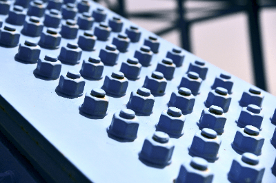
Unlike bolts used in general machinery, high-strength bolts are much more substantial.

The commonly used steel material called SS400 has a tensile strength of 400 N/mm2, but the material used for High strength bolts has a strength of 800 N/mm2 at the lowest.

Therefore, it is used in construction, not for general mechanical applications. In particular, they are widely used as bolts for fixing steel materials together in friction-jointed joints, often employed in steel construction.

These bolts are still widely used today.

Uses of High-Strength Bolts

Uses of high-strength bolts are mainly in the field of construction. There are many ways to build a building structure; among them, it is straightforward to construct a building structure with steel frames compared to concrete structures.

High-strength bolts are used to join steel members together.

In the case of steel construction, welding steel frames together is very time-consuming, and the quality is not stable with on-site welding, so they are joined by a method called friction welding.

High-strength bolts are used because high torque is required to generate this frictional force.

Principle of High Strength Bolts

Since high-strength bolts are used in steel-frame joints, where high torque is required, chrome and molybdenum steel has been used for many years, but nowadays, low-carbon boron-added steel is widely used.

This has made it possible to prevent delayed fracture, which has been a problem with chromium and chrome molybdenum steels. High-strength bolts are divided into two types according to their shape and usage: Torsia-type high-strength bolts and high-strength hexagonal bolts.

The main difference between these two bolts is that the torusia-type high-strength bolt has a particular shape for the fastening portion and requires a dedicated tool. However, the tightening part is shaped to break if tightened with more than the specified torque, so torque management is straightforward.

On the other hand, High strength bolts can be tightened using the same wrenches and other tools as general bolts and nuts, but torque control may be neglected.

The general disadvantage of high-strength bolts is that they are more expensive than ordinary hex bolts. However, since hexagonal bolts of common materials cannot handle high torque, they are always used in construction sites.

High-Strength Bolt Friction Joints

High-strength bolt friction joining is a method of joining steel plates by frictional force generated on the contact surfaces of the steel plates by tightening them together with the strong axial force applied to the high-strength bolt. This method is used in construction fields such as road bridges and skyscrapers. Stronger fastening is required because of the additional surface bonding force between the steel plates compared to fastening with only the axial force of a normal bolt. Another advantage of this method is that it does not require firearms like rivet joints and does not require professional skills like welding.

Since the frictional force between steel plates must be high, the contact surfaces must be slip-resistant. Slip resistance is determined by the “slip coefficient” specified in the Building Standard Law, which must be 0.45 or higher. The higher the slip coefficient, the greater the resistance and frictional force, so a friction surface treatment is applied to roughen the surface of the steel plate in advance.

There are three types of friction surface treatments: “red rust treatment,” “shot blasting,” and “phosphate treatment.

Red Rust Generation Treatment

In the red rust-generating treatment, the contact area of the steel plate is roughened by applying a grinder, etc., and is oxidized in the atmosphere.

Shot Blast Treatment

Shot blasting treatment is a method in which fine balls (silica sand or steel balls) called media are blown together with compressed air to roughen the surface with fine irregularities. After shot blasting, the surface loses its metallic luster.

Phosphate Treatment

This simple method of applying a phosphate chemical to the bonding surface is widely used because it requires little time and effort. However, working in rainy or humid environments is strictly forbidden, as moisture will cause the bolts to fail to adhere to the surface and peel off.

Difference Between High Strength Bolts and High Tension Bolts

High-strength and high-tensile bolts are identical, and they are no different. They are called “high-strength” and “high-tension” because they are made of high-tension steel (high-tension steel). There are different types of high-tensile steel, including those with a higher nickel content of about 3% to increase salt resistance near the coast and weather-resistant ones with increased amounts of Ni and Cu added to increase atmospheric corrosion resistance.

How to Read High-Strength Bolt

It is read as a “high-strength bolt” or “high-tension bolt.” Note that they are also called high-tension bolts.

カテゴリー
category_usa

Wind Sensors

What Is a Wind Sensor?

Wind Sensor

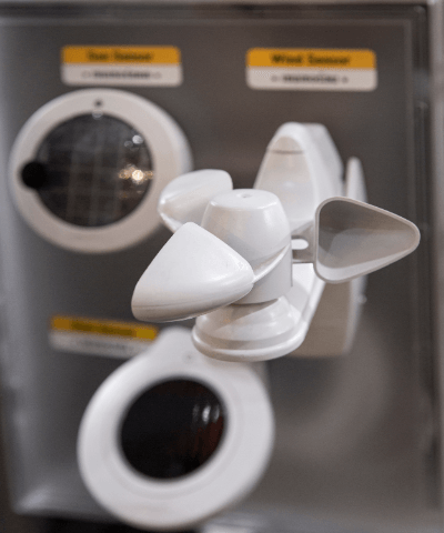
Wind sensors, also known as anemometers, measure air or gas flow speed. These devices come in various designs, each suited to specific applications and locations. While flowmeters are common for measuring gas flow in pipes, wind sensors excel in open or semi-open environments, often calculating wind speed through pressure measurements.

Applications

Wind sensors find utility in numerous settings, from industrial sites and sporting events to meteorological studies. They’re crucial in:

  • Air conditioning maintenance and inspection.
  • Smoke segregation efficacy verification.
  • Measuring ventilation fans’ air velocity.
  • Monitoring exhaust from HVAC systems.
  • Conducting indoor convection and air quality assessments.
  • Ensuring safety in elevated outdoor locations by monitoring wind speed.
  • Weather observation and drone flight condition verification.

Operating Principles

Wind sensors employ various mechanisms to measure wind speed:

  • Wind Cup Anemometers: Utilize rotating cups to gauge wind speed based on rotation frequency. Suitable for general outdoor use but less responsive at low speeds.
  • Ultrasonic Wind Sensors: Measure wind speed and direction using the Doppler effect, ideal for durable, moving-part-free outdoor applications.
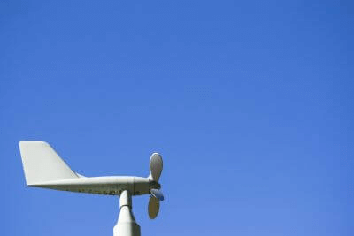
  • Anemometers for Wind Direction: Combine propeller rotation for speed measurement with a weather vane for direction.
  • Hot-Wire Anemometers: Employ a temperature-sensitive element to measure cooling effects of wind, optimal for indoor environments.
  • Pitot Tube Sensors: Use differential pressure to calculate wind speed, commonly found in industrial settings.
  • Vane Wheel Sensors: Determine wind speed by counting the rotations of a wind-driven vane.

Choosing the Right Wind Sensor

Selection criteria include:

  • Indoor vs. outdoor application.
  • Stationary vs. portable use.
  • Specific requirements such as wind speed range, accuracy, and response time, especially important for specialized applications like hot-wire anemometers.
カテゴリー
category_usa

Wind Tunnels

What Is a Wind Tunnel?

A wind tunnel is a test facility for measuring and analyzing the forces acting on a fixed model of a building, airplane, automobile, etc., and the flow of wind around the model. By sending an airflow around a model, it is possible to simulate flight conditions for airplanes and driving conditions for automobiles. By matching the Reynolds number, even if the model is smaller than the actual aircraft, it is possible to obtain almost the same experimental results as actual flight or driving.

Wind tunnels come in all sizes: In the test facility of JAXA (Japan’s national air and space agency), there is a low-speed wind tunnel, that is the largest in the aerospace field in Japan, measuring 5 to 6 meters in length and width, where the model is fixed. In the United States, there is a huge wind tunnel measuring about 24 meters in length and 37 meters in width.

Uses of Wind Tunnels

Uses of wind tunnels are extremely wide-ranging, including the use of measurement data for aircraft and rockets, for which fluid design is important, as well as for automobiles, railroads, and the design of high-rise buildings and bridges, for which consideration of wind effects is important.

In addition to basic measurements of forces acting on the model, such as lift and drag, and pressure on the model surface, wind tunnel experiments also utilize particle image velocimetry (PIV) to visualize airflow.

Wind tunnels consist of a blower, a nozzle section, a rectifying plate, a measurement section, and a diffuser section. The same is true for flow visualization using PIV and other methods.

The Principle of Wind Tunnels

The Principle of Wind tunnels is to predict the real-world wind (fluid) flow by measuring the actual wind flow by changing a large object to be analyzed into a small, similar-shaped model, subjecting it to actual wind and matching the Reynolds number under the right conditions. Wind tunnels are experimental facilities that use Reynolds’ law to measure and analyze the fluid effects of actual ambient wind.

By matching the Reynolds number Re, the flow of ambient fluid is equal when the geometry of the actual machine and the model are similar, which is called Reynolds’ law in fluid mechanics. The Reynolds number Re can be calculated by the following equation.

The inertia of the momentum of the entire fluid (velocity x length) ÷ physical quantity calculated by kinematic viscosity (dimensionless quantity)

For example, considering the case where a precise model of a car running is made 1/10th the size of the actual car, Reynolds’ law of similarity can be satisfied if the wind tunnel wind speed is set to 10 times the actual running speed. However, since kinematic viscosity varies with temperature, it is also important to adjust the temperature to match the kinematic viscosity of the actual run with the wind tunnel speed.

Types of Wind Tunnels

Wind tunnels can be broadly classified into two types of structures

1. Simple Blowout Type

The simple blowout type, also called an Eiffel-type wind tunnel, has the advantages of a simple structure and small installation space but has the disadvantage of requiring a large amount of power to provide airflow.

2. Circulating Flow Type

The circulatory flow type requires less power to generate air velocity and the flow is more stable, but it has the disadvantage that the temperature of the airflow rises significantly. The device itself tends to be large in scale. The Goettingen-type Wind tunnel is a well-known example.

More Information on Wind Tunnels

Application of CFD

CFD (Computational Fluid Dynamics) technology, which uses simulations to predict the results of wind tunnel tests, has evolved rapidly in recent years. Wind tunnels are used for scaled-down models compared to actual test rigs and buildings, but the prototyping cost and man-hours involved are still expensive.

CFD, on the other hand, involves the cost of installing PCs and software, but the subsequent operating costs can be reduced compared to Wind tunnel testing. However, to reach a level where CFD data alone is sufficient for designing without wind tunnel testing, it is essential to accumulate data and determine detailed parameters. The complementary relationship between CFD and Wind tunnel data verification is improving design accuracy and reducing man-hour costs at an ever-increasing pace.

カテゴリー
category_usa

Anemometer

What Is an Anemometer?

Anemometers

An anemometer is an instrument that has the functions of both an anemometer and an anemometer.

It is used to observe wind conditions because it can measure both wind speed and direction at the same time. There are many types of anemometers; the three main types being the wind cup type, windmill type, and ultrasonic type. There are 36 wind directions, and the average direction for 10 minutes or 2 minutes is displayed as the wind direction.

Wind speed is the distance traveled by air per unit of time, and is also displayed as the average value of wind speed over a 10-minute or 2-minute period, using the unit of knots. From large high-precision observations to small portable ones, they are suitable for a wide range of applications.

Uses of Anemometers

In large high-precision observation applications, anemometers are very important indicators for predicting weather conditions because they enable us to understand atmospheric movement by observing wind conditions.

By understanding the movement of clouds and the strength of winds at different wind observation sites, it is possible to predict disasters and weather conditions. Issuing cautions and warnings for typhoons and waves is useful to prevent the spread of damage.

In addition, since wind information is essential for the safe operation of ships and aircraft, anemometers are installed at airports and coastal areas to keep track of real-time wind information.

Small, portable anemometers are used to observe wind conditions in indoor environments. Specifically, it is used during inspections and maintenance inspections of equipment such as air conditioners and ducts, and for investigating the state of air circulation in clean rooms.

Principle of Anemometers

1. Wind Cup Type Anemometer

The anemometer consists of hemispherical or conical cups mounted in three to four directions around a rotating shaft. Wind speed is measured by measuring the speed at which the cups rotate in response to the wind.

2. Windmill Type Wind Direction Anemometer

It consists of a body part and a propeller part. The propeller attached to the tip of the body receives wind and rotates to measure wind speed, and the body is streamlined to move in the direction of the wind to measure wind direction.

3. Ultrasonic Anemometers

Ultrasonic anemometers are used by installing a pair of sound wave receivers and transmitters. speed from the time the sound waves are emitted into the air to the time they are received.

Other Information on Anemometers

Location of Anemometers

1. Observation Location
Anemometers are generally installed in flat, open areas because they are easily affected by wind. The distance from obstacles such as buildings and trees should be at least 10 times the height of the obstacle.

Wind blowing from the edge of a building or the top of an uneven cliff can greatly affect wind measurements. Although it is relatively common for anemometers to be installed on building rooftops using steel towers, it is desirable to select a location that is less affected by blowing wind, rooftop structures such as cooling towers, and wind turbulence caused by the size and height of the building.

It is also important to choose a location free from wind turbulence when selecting an observation site for an anemometer. that is not affected by wind turbulence.

2. Installation Location
Anemometers should be installed on a tower or post so that the bottom of the instrument support is horizontal. This will ensure accurate readings. If the anemometer is not level, the cups will not rotate evenly and the readings will be inaccurate.

To determine if it is level, use a level. A level can be used to verify that the top of the mounting base is level. Note that if the anemometer is not level, the cups will not rotate evenly and the readings will be inaccurate.

3. Height
The height of the anemometer should be mounted with two points in mind.

First, the anemometer should be installed at a height where it is not obstructed by plants, trees, or other structures, and second, it should not be affected by temperature gradients near the ground surface. The ideal height for an anemometer is 10 feet (3 meters). If the purpose is clear, such as observing the wind speed on a bridge or at the exit of a tunnel to ensure the safe operation of a car or train, it is necessary to select the installation location and height of the measuring instrument according to the purpose.

カテゴリー
category_usa

Wind Turbines

What Is a Wind Turbine?

Wind Turbines

A wind turbine is a device that uses the force of the wind to turn its blades and convert that rotational power into electricity using a generator.

Unlike thermal power generation, wind power generators use only natural energy and are attracting attention as clean power generators. There are also offshore wind turbines, which are installed in the sea, providing more space than on land, and generating more stable power. They are mainly used in Europe.

Advantages of Wind Power Generation

  • Environmentally friendly, as no carbon dioxide is emitted during power generation.
  • Since wind power is used as energy, power can be generated as long as the wind blows.

Disadvantages of Wind Power Generation

  • Noise is generated during power generation.
  • Because power is generated by wind, the amount of power generated is easily affected by weather and other factors.

Introduction of Wind Turbines

Wind Power Generation Ranking by Country in the World

Wind power generation is now a globally adopted power generation method. The countries with the largest amount of wind power generators are, from the top, “China, the United States, Germany, India, and Spain” (2017).

Wind Power Installation Location Ranking by Prefecture

The ranking of wind power installations by prefecture is as follows: 1st: Hokkaido, 304 units; 2nd: Aomori, 253 units; 3rd: Akita, 210 units.

In Japan, wind power is supposed to generate 0.8% of the total amount of energy according to the 2019 Power Generation Survey. Wind power generation requires that the installation site be in an area with large tracts of land, where wind power is strong, and where there are few residents nearby due to noise and bird problems. Therefore, in Japan, where land is scarce, solar power is the most common method of generating electricity using natural energy, and land-based wind power is not very suitable.

Principles of Wind Turbines

This section describes how wind power generation works and the Principle of wind power generation. Wind power generation works by first capturing the force of the wind with large wings called blades, which return the wind coming mainly from the front to rotational force. The blades are then connected to a gearbox at the center, which uses gears to amplify the rotational force that is required for the generator. The rotational power transmitted from the gearbox is then converted by the generator and sent to the substation.

There are two types of wind turbines, depending on the direction of the blades: the horizontal-axis type and the vertical-axis type. The horizontal-axis type is a wind turbine with its blades perpendicular to the ground, while the vertical-axis type rotates parallel to the ground. Vertical-axis wind turbines are characterized by their low noise level compared to horizontal-axis wind turbines. However, because of its lower output, it is used in small-scale applications such as parks.

Wind Turbines Size

Wind turbines are defined by the International Electrotechnical Commission (IEC) as follows: products with an output of less than 1 kW are classified as micro wind turbines, those with an output of 1 to 50 kW as small wind turbines, and those with an output of 50 kW or more as large wind turbines.

1. Small Wind Turbine

Small Wind turbines are defined as those with a wind-receiving area of 200 m2 or less and a propeller diameter of 16 m or less.

2. 600kW Large Wind Turbine

For large wind turbines with a rated output of 600kW, the tower height is generally 40-50m and the propeller diameter is 45-50m.

*As a rough guide, 40m is equivalent to a 10-story office building.

3. 1,000 kW to 2,000 kW Large Wind Turbines

For large wind turbines with a rated output of 1,000kW to 2,000kW, the height of the tower is 60 to 80 meters and the diameter of the propeller is 60 to 90 meters.

*As a rough guide, 60m is equivalent to a 15-story office building.

Location of Wind Turbine

Wind turbines can be installed in two main locations: onshore and offshore.

1. Onshore Wind Turbines

Onshore Wind turbines can be installed as long as there is a large area of land where winds of a certain speed (generally 6 m/year or higher) are blowing steadily.

In Japan, these systems are often installed in the Hokkaido, Tohoku, and Kyushu regions.

When installing in Japan, the challenge is not only to harmonize with the surrounding environment but also to be able to cope with typhoons and other weather conditions. When considering the installation of a small wind turbine, it is said that an area of approximately 130 m2 is required. It is important to consider the installation area, its location in relation to neighboring residences, the natural environment, and wind conditions.

2. Offshore Wind Turbine

Offshore wind turbines are wind turbines built on the surface of a lake or ocean to generate electricity.

Compared to land-based wind power generation, offshore wind turbines can generate more wind power in a more stable manner and avoid risks such as noise and human casualties. Wind turbines are installed not only on the sea but also in lakes, fjords, harbors, and other locations.

The biggest advantage of offshore wind power is that it can harness the power of the wind without occupying valuable land resources. In addition, offshore wind farms can be built in locations where wind speeds are strong, enabling them to generate high amounts of electricity. With research and development of renewable energy sources becoming more active, there are high expectations for offshore wind power generation as a power generation method that will play a key role in supplying energy for the next generation.

The growing popularity of offshore wind power is due to growing global interest in decarbonization, and Japan needs to increase its generation of renewable energy if it is to achieve the goal set in 2020 of reducing greenhouse gas emissions to virtually zero by 2050.

Generally speaking, renewable energy sources include hydroelectric power and solar power, but the amount of power generated by these sources depends on the amount of rainfall and sunlight (time of day), respectively. Wind power generation can compensate for the weakness of solar power generation because it can generate electricity stably even at night.

However, wind power generation cannot generate power during periods of low wind or when typhoons pass, so it is important to supplement it with other power generation methods rather than relying on one method alone. Increasing offshore power generation will help eliminate fossil fuel power plants and contribute to achieving the goal of reducing greenhouse gas emissions to nearly zero by 2050.

The biggest disadvantage of offshore wind power is its high cost. The initial investment and maintenance costs for offshore wind power are much higher than for onshore wind power. Another disadvantage is the potential for negative environmental impacts. There are concerns about noise, deterioration of the landscape, and impact on marine life.

Floating Offshore Wind Turbine

There are two types of offshore Wind turbines: the “implantation type,” in which the generator is fixed to the seafloor, and the “floating type,” in which the generator floats on the seafloor.

The implantable type is limited to shallow waters, but it is robust, and large generators can be installed. On the other hand, the floating type is limited in size and efficiency but can be installed in large numbers in any location.

In Europe and the United States, the implantation type is the mainstream. On the other hand, floating wind turbines, which have fewer restrictions on installation location, are beginning to attract attention in Japan because they can increase the amount of power generated by offshore wind turbines in deep water near the coast. The installation of floating wind turbines has many challenges in terms of cost and power transportation, and further research is needed.
カテゴリー
category_usa

Microscope Cameras

What Is a Microscope Camera?

A Microscope camera is a camera that is attached to a microscope.

By using a Microscope camera, you can take still or moving images of what you are observing under the microscope. It is possible to observe through a monitor and save microscopic images as data without having to look through the eyepiece of the microscope.

Digitalization has made it possible to connect to computers and monitors via USB or HDMI terminals, making it easy to perform measurement and analysis while simultaneously observing, or to observe in real time with a large group of people.

Uses of Microscope Cameras

Microscope cameras are used for a variety of purposes in research and manufacturing, including observation, recording, and measurement.

For example, when visual confirmation by a single person alone is not sufficient evidence, the observation results can be saved as data to be presented as evidence in research presentations or business reports.

If you want to perform measurement or analysis during observation, you can connect the Microscope camera to a computer and work simultaneously with software. It is also used to share the results on a monitor during practical training or presentations or to visually explain the results to patients during medical examinations.

Principles of Microscope Cameras

A microscope observes a magnified image produced by an objective lens.

Microscope cameras have a photo projection lens (camera adapter) and a camera body. The magnified image obtained by the objective lens is converted into an electrical signal by using the photographic projection lens to form an image on the image sensor of the camera body, and the signal is output as an image.

There are several types of photographic projection lenses (camera adapters), such as those attached to the trinocular tube of a Microscope camera or those attached in place of the eyepiece. Microscope cameras capture the high-magnification object captured by the microscope, so it is necessary to quickly determine which part of the object is in focus for observation.

To accommodate quick manual movement of the microscope, each manufacturer has its innovations to obtain high-quality images at high speed by increasing resolution and frame rate.

Types of Microscope Cameras

Microscope cameras are available as color cameras and monochrome cameras. Since characteristics such as color reproducibility and resolution differ depending on the camera, it is necessary to select a Microscope camera according to the characteristics of the object to be observed and the uses of the camera.

1. Color Camera

Records the condition of the specimen being observed along with its color. Camera manufacturers use color correction technology to express colors similar to those seen through the eyepiece.

2. Monochrome Camera

By using an electron multiplication function element, a monochrome camera can detect faint light that cannot be detected by a color camera. By making it possible to visualize specimens with faint fluorescence, it demonstrates its capability in specific applications.

How to Choose a Microscope Camera

When selecting a Microscope camera, pay attention to the following items and choose one that is suited to the characteristics of the object to be observed and its uses.

1. Resolution

This indicates how finely the image can be resolved. The higher the value, the better the image quality, but the larger the image data size.

2. Frame Rate

The frame rate indicates how many images can be output per second. The higher the value, the less likely the images will be blurred or delayed even when the specimen or microscope is moving quickly.

3. Sensitivity

Sensitivity refers to the efficiency with which the image sensor converts light into electrical signals. The higher the sensitivity, the more the camera can capture images even with weak light. Due to the characteristics of the image sensor, the lower the light level, the higher the electrical noise, which is why the term “low noise” or “high S/N” is sometimes used.

4. Color Reproducibility

The human eye and the sensor of a Microscope camera have different sensitivities to light and color. For this reason, Microscope cameras are processed to match the color of the specimen being observed. Each manufacturer has its characteristics, so it is recommended to check with them.

カテゴリー
category_usa

Chamfering Machinery

What Is Chamfering Machinery?

Chamfering machinery is a processing machine that removes the corners of wood, steel, and other materials by turning the corners into a C-face.

It also plays a role in preventing injury from the standing of corners, especially on hard materials.

If there are chamfering instructions on the drawing, the drawing will show “C2”.

This means that the length and width are chamfered with chamfering machinery to remove 2 mm.

Depending on the material and other factors, chamfering machinery can be changed to remove the surface.

Chamfering machinery chips are also available in different types, such as wood and steel.

Uses of Chamfering Machinery

Chamfering machinery is used to remove corners.

The following is a description of the uses of Chamfering machinery.

Handheld Type Chamfering Machinery

  • This tool is used for chamfering steel and other materials.
  • This machine can be carried to high places such as a job site.

Handy Type Chamfering Machinery for Curved Line Processing

  • This is a tool for chamfering steel materials.
  • It is not limited to C-face but can also process R-shaped curves.

Desktop Type Chamfering Machinery

  • Chamfering machine for steel materials, etc.

Pipe Chamfering Machinery

  • Chamfering machinery for outside and inside of steel pipes.

Features of Chamfering Machinery

Chamfering machinery is used to remove corners.


Features of Chamfering machinery are described below.

Processing shape of chamfering

  • C chamfer
  • R chamfer
  • Thread chamfering (fine chamfering)


Handy Type Chamfering Machinery

  • Portable type.
  • This chamfering machine is used when chamfering cannot be performed with larger machines.

Handheld Chamfering Machinery for Curved Line Processing

  • Portable type.
  • Shapes that can be chamfered
    • Hole diameter: Delete corner
    • Radius: Delete corner
    • Groove: Delete corner
    • Square: Delete corner
  • R chamfer: radius corners
    • Chamfering is available in a wide range of shapes.

Desktop Type Chamfering Machinery

  • Chamfering machinery to remove burrs after cutting.

Pipe Chamfering MachineryMentry

  • Tool only for chamfering
  • Chamfering inside and outside of the pipe.
  • Mainly for PVC pipes
  • Disadvantages
    • Steel pipes are tough

Electric Pipe Reamer

  • Used primarily for chamfering steel pipes
  • Fast because it is electric
  • Can take inner and outer faces
  • Disadvantages
    • Equipment is expensive

Pipe Reamer Manual

  • Can be chamfered while turning by hand
  • Can ream both inside and outside surfaces
  • Can be used without a power source
  • Disadvantages
    • Aligned for each pipe type and diameter


カテゴリー
category_usa

Emergency Power Generators

What Is an Emergency Power Generator?

Emergency Power Generators

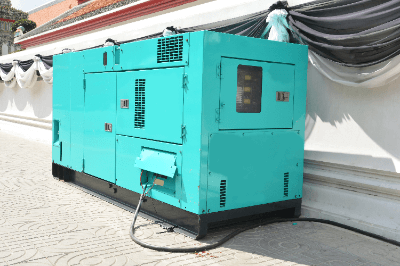
Emergency power generators are power generation devices installed for disaster prevention and security purposes in anticipation of sudden power outages due to disasters.

If the power supply stops, there is a risk of secondary disasters due to communication lines being interrupted in buildings, hospitals, and other facilities. The installation of emergency generators is essential to prepare for such a situation.

Emergency generators are mainly engine power generators and gas turbine power generators. It is vital to select the right one for the application and the building in which it will be used. Both are highly reliable and can be used as high-quality power supply units.

Uses of Emergency Power Generators

Emergency power generators are used in locations with a risk of secondary disasters in the event of a sudden power outage. Examples of use are listed below.

In some of the above cases, the installation of emergency power sources is required by law.

Principle of Emergency Power Generators

The power generation mechanism uses the principle of electromagnetic induction to generate electromotive force when a conductor crosses a magnetic field.

Since emergency generators must be able to be used reliably in an emergency, they are equipped with a system that detects power outages and quickly switches to the generated power source. They are also vibration-resistant so that they can operate even in an earthquake.

Types of Emergency Power Generators

Emergency generators are mainly engine generators and gas turbine generators.

Diesel generators use a diesel engine for motive power, and an alternator is directly connected to the diesel engine to generate electricity. It takes a short time to start and has a high thermal efficiency of about 35% to 40%. They are also highly reliable power generators in terms of their start-up.

Gas turbine generators are air-cooled for emergency use. Since no cooling water is required, there is no risk of turbine failure due to freezing or water cutoff. Another feature is that the installation area is smaller than for diesel engines.

Other Information on Emergency Power Generators

Emergency power generators must undergo three periodic inspections to ensure reliable operation in an emergency.

Periodic Inspection Based on the Electricity Business Act

This inspection performs a no-load operation (dry run) for about 5 minutes with the electrical system turned on.

Periodic Inspection Based on the Fire Service Act

A visual functional inspection is conducted every six months, and a no-load operation is done annually.

Load Test Operation in Accordance With the Fire Service Act

This test must be conducted once a year. Emergency power generators are connected to a load test device and operated continuously for 30 minutes with a load of 30% or more. During the load test operation, we confirm that there are no abnormalities, such as abnormal vibration or heat generation, in the emergency power generator and that the operation is normal. In addition, it also serves to burn off the carbon generated during the no-load operation.

As mentioned above, the load test operation requires the connection of the load test equipment to the emergency power generator. However, this may be difficult depending on the location of the emergency power generator. However, the Fire Service Law was revised in 2019, and gas turbine emergency power generators are no longer required to perform load test operations. Even for equipment requiring a load test, the inspection is now considered equivalent to a load test by conducting the prescribed internal observations if it is challenging to conduct a load test.

Emergency power generators vary widely in price, depending on the generation method and capacity. For a small unit for home use, a 45,000mAh/3.7V/167Wh/rated 150W solar-charged and lithium-ion battery storage type generator can be purchased for 10,000 yen or less.

On the other hand, emergency power generators used in stores and server rooms are gas turbine-powered and cost several million yen or more. Many engine emergency power generators are also available for large facilities, and like gas turbine generators, they are priced in the millions of yen to several million yen range.

カテゴリー
category_usa

Non-Destructive Testing (NDT) Systems

What Is a Non-Destructive Testing (NDT) System?

Non-Destructive Testing (NDT) Systems

Non-destructive testing (NDT) systems inspect an object’s interior or surface without destroying or damaging it.

The purpose of the inspection is to check for scratches, defects, cracks, voids (bubbles), etc., inside or on the surface of the inspected object. This inspection allows us to examine manufactured products without destroying them and to provide reliability and assurance.

Many types of non-destructive testing (NDT) systems are based on various principles. These systems can be used for multiple purposes. A certification test for NDT systems determines whether a person is proficient in using NDT systems and meets the inspection techniques for each of the six inspection categories as specified.

Uses of Non-Destructive Testing (NDT) Systems

The equipment is used to determine the presence or absence of melts and weld defects inside welds, cracks, voids, and other imperfections and defects inside materials, as well as scratches and cracks on the surface of materials that cannot be identified visually.

Non-destructive testing does not always require equipment (visual inspection, penetrant testing, etc.), but there are many situations where equipment is needed. For example, non-destructive inspection is used for aging steel frames inside concrete buildings, bridges, tunnels, and elevated bridges; in-process inspection of steel, copper, and aluminum pipes; aircraft fuselage inspection; and inspection of containers and pipes inside nuclear power plants. X-ray imaging, CT scans, and magnetic resonance imaging used for inspecting the human body are also forms of non-destructive testing (NDT) systems.

Principles of Non-Destructive Testing (NDT) Systems

Non-destructive testing involves a variety of methods based on several principles. This section describes the inspection methods and principles that require NDT systems.

1. Ultrasonic Testing Equipment

3515_Non-Destructive-Testing-NDT-Systems_非破壊検査装置-1.png

Figure 1. Principle of ultrasonic testing systems

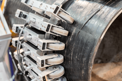
Ultrasonic testing equipment emits high-voltage ultrasonic waves from an ultrasonic probe. It receives echoes when vibrations propagate or are transmitted through the surface or interior of an object and are reflected by internal defects or surface flaws, thereby identifying the location and size of internal defects or surface flaws.

3515_Non-Destructive-Testing-NDT-Systems_非破壊検査装置-2.png

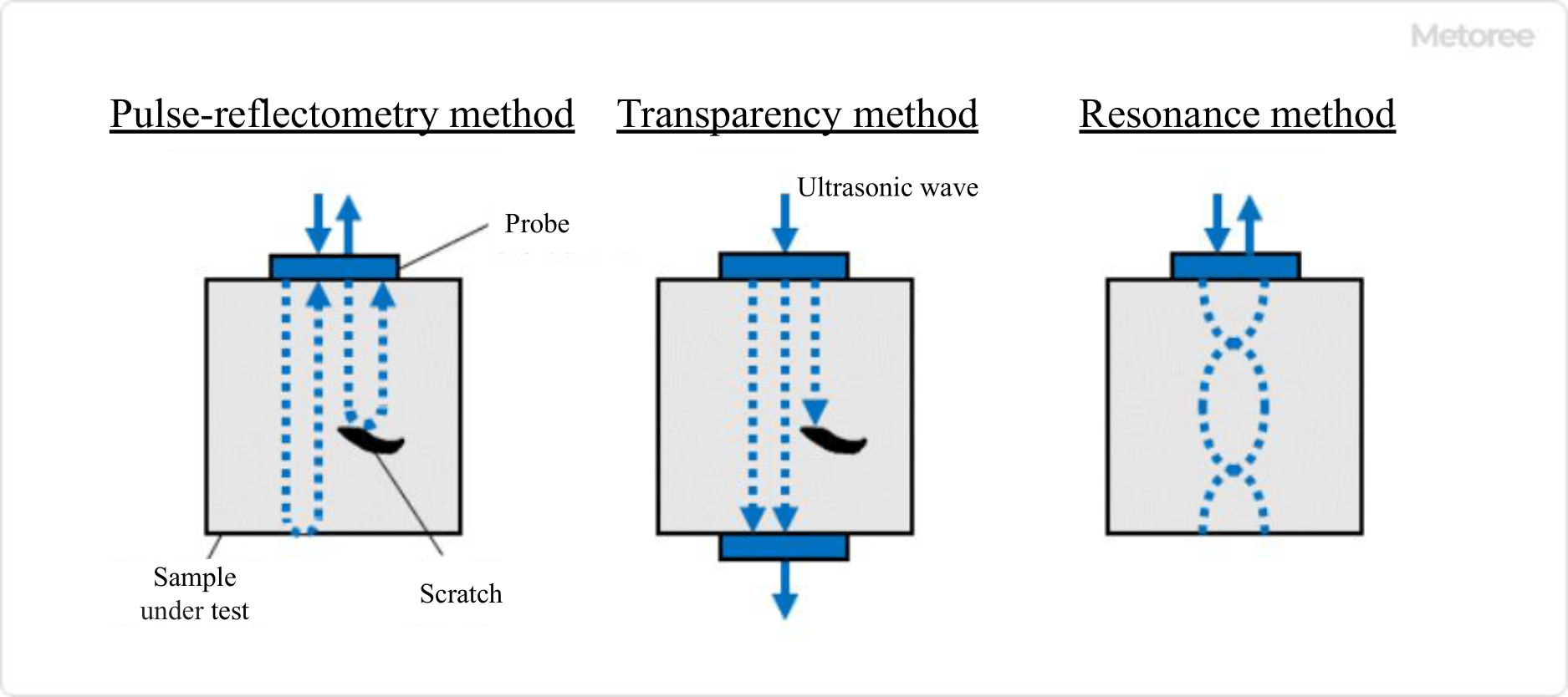
Figure 2. Types of ultrasonic testing systems

There are three types of ultrasonic inspection methods: the pulse reflection method, the transmission method, and the resonance method.

2. Magnetic Particle Inspection System

3515_Non-Destructive-Testing-NDT-Systems_非破壊検査装置-3.png

Figure 3. Principle of magnetic particle inspection systems

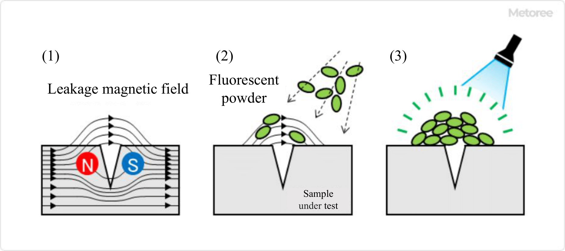
Magnetic particle inspection equipment is a method that utilizes the magnetic flux disorder generated in the surface flaw area.

When a strong magnetic field is applied to a magnetic object to be inspected, a disturbance of the magnetic flux is generated in the area where the surface flaw is located. When colored iron powder or fluorescent magnetic powder is sprinkled on the inspected object, the iron powder or fluorescent magnetic powder aligns with the shape of the magnetic flux leakage at the surface defects, making them visible as a pattern or a set of lights.

Typically, this method is mainly used for visual inspection without equipment, but automatic magnetic particle inspection equipment equipped with an image recognition device is also used.

3. Eddy Current Flaw Detector

3515_Non-Destructive-Testing-NDT-Systems_非破壊検査装置-4.png

Figure 4. Principle of eddy current testing systems

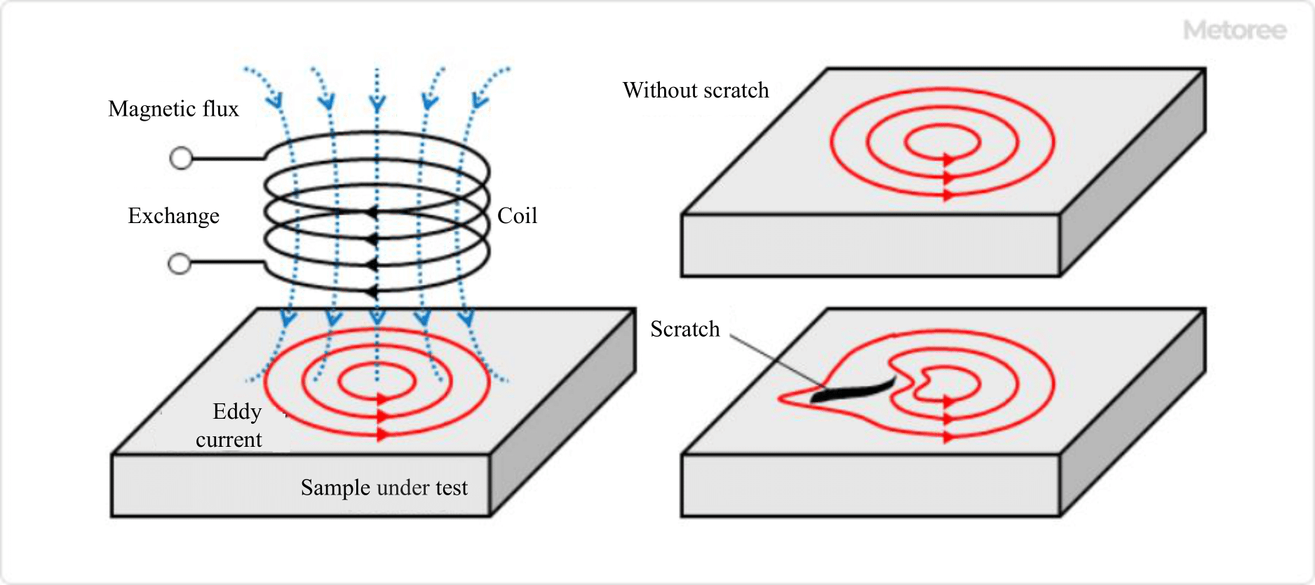
In the eddy current flaw detector, a probe with an embedded coil of copper wire is brought into proximity to the surface of the object to be inspected by passing an alternating current through it, and the presence of flaws is determined by measuring the turbulence of the overcurrent generated on the object’s surface.

Since the accuracy and sensitivity of flaw detection require a coil shape that matches the object to be inspected, this type of equipment is often used when inspecting many objects of the same shape.

4. Radiation Transmission Testing Equipment

3515_Non-Destructive-Testing-NDT-Systems_非破壊検査装置-5.png

Figure 5. Principle of radiation transmission testing systems

X-rays penetrate the object to be inspected using high-energy X-rays, which have the highest penetrating performance among all types of radiation. A detector receives the transmitted radiation, and the signal is used for drawing or image recognition to detect defects inside the inspected object.

In the past, defects were determined visually by sensitizing a film with radiation, as in the X-ray inspection of the human body. Still, more and more equipment automatically identifies defects by image recognition.

Other Information on Non-Destructive Testing (NDT) Systems

1. Disadvantages of Non-Destructive Testing (NDT) Systems

Non-destructive testing (NDT) systems are very useful, but it is essential to understand that each measurement principle has disadvantages.

Ultrasonic Testing

Spherical flaws and cavities are difficult to detect because echoes are reflected in all directions. It is also not suitable for inspecting complex shapes or coarse-grained materials. This is because minute echoes generated randomly at each tissue’s boundaries spread randomly and are superimposed as noise on the echoes to be detected.

Magnetic Powder Inspection

Not applicable for the inspection of non-magnetic materials.

Eddy Current Inspection

It is difficult to inspect nonconductive materials and detect internal defects. It is also not suitable for objects with complex shapes.

Radiation Penetration Test

Special equipment is required to inspect thick objects because of the extremely high-energy radiation required. It is also not good at detecting surface defects and closely adhered cracks. Above all, radiation safety control requires careful attention.

2. Market Size of Non-destructive Testing (NDT) System

The market size of non-destructive testing in Japan is estimated to be 200~300 billion yen when adding the inspection service market to equipment sales.

Increasingly, manufacturers are not only conducting inspections in-house but are also outsourcing to inspection companies. As cities and industries become more sophisticated, safety, security, and quality control are becoming more important, and non-destructive testing is playing an increasingly important role. From the perspective of safety and consideration for the natural environment, the market for non-destructive testing is expected to grow further.

Construction Industry

In the construction and civil engineering industries, the market for non-destructive testing and diagnosis of concrete structures will continue to grow. This is due to the growing importance of extending the service life of concrete structures and the need to perform preventive maintenance before deterioration becomes pronounced.

Other Industries

Non-destructive testing is also expected to expand in the energy and heavy industry sectors, promising markets for future growth.