カテゴリー
category_usa

Thermal Conductivity Analyzers

What Is a Thermal Conductivity Analyzer?

A thermal conductivity analyzer is a device used to measure the thermal conductivity of a material.

There are various types, such as those that use a heat plate, hot wire, or laser. Thermal conductivity is the value of the ease of heat transfer within a material and is one of the points that characterize a material. For example, pots and pans can be heated faster if the thermal conductivity is high and retains heat better if the thermal conductivity is low.

Uses of Thermal Conductivity Analyzers

Thermal conductivity analyzers are used to evaluate product manufacturing methods and to develop new materials and products.

1. Evaluation of Heat Retention Performance

For example, the thermal insulation performance of a storage container is evaluated. The lower the thermal conductivity, the higher the thermal insulation and the longer it can keep warm. We measure thermal conductivity as an indicator of this performance.

2. Development of Heat-Dissipating Materials

Recently, thermal conductivity has been increasingly used in the development of heat-dissipating materials, as heat dissipation is an important factor in CPUs and other devices to prevent thermal runaway caused by heat generation.

For example, the higher the thermal conductivity of the thermal conductive grease used to improve heat dissipation, the higher the heat dissipation.

Principle of Thermal Conductivity Analyzers

3806_Thermal-Conductivity-Analyzers_熱伝導率測定器-1.png

Figure 1. Steady-state and non-steady-state methods

Thermal Conductivity Analyzers can be broadly classified into the Steady-State Method and the Non-Steady-State Method.

1. Steady-State Method

The steady-state method directly measures thermal conductivity by generating a steady thermal gradient. A steady heat flow is generated by making one side of the sample hot and the other side cold.

By measuring the heat flux from a heat flux meter or a material of known thermal conductivity and temperature, the thermal conductivity can be measured from the temperature difference generated in the sample. The simple principle makes accurate measurements possible, but temperature control of the sample surface and heat dissipation to the surroundings can cause errors. Another disadvantage is that it takes a lot of time to reach a steady state.

2. Transient Method

The transient method is a method to measure thermal conductivity by applying non-steady heat to a sample. By measuring the change in sample temperature over time after heat is applied, the thermal conductivity can be calculated. There are two methods of applying heat: the laser flash method using a laser beam and the hot wire method using a heater wire, etc. The laser flash method uses a laser beam to apply heat to the sample.

In the laser flash method, the sample is heated using a laser beam and is detected by an infrared sensor. The disadvantage of this method is that it is difficult to detect samples with too small a thermal conductivity. In the hot wire method, the sample is heated by passing a hot wire inside the sample. This method can be used to measure without distinction between solids and liquids.

Other Information on Thermal Conductivity Analyzer

1. Difference From Thermal Diffusivity Measurement Device

3806_Thermal-Conductivity-Analyzers_熱伝導率測定器-2.png

Figure 2. Thermal diffusivity and thermal conductivity

Thermal diffusivity is generally measured by devices using the laser flash method, but thermal conductivity cannot be measured directly. Thermal conductivity can be obtained by multiplying the thermal diffusivity obtained with a laser flash measurement device by the specific heat and density.

The specific heat is measured by a differential thermal analyzer (DSC), and the density is measured by a method such as the displacement method known as Archimedes’ method in water. The laser flash method can be used to measure the thermal diffusivity of a wide range of materials, including rubber, plastics, and other polymers, ceramics, and even metals. On the other hand, there are restrictions on test conditions, and the materials to be measured are dense rather than porous.

The material must be free of defects, such as shrinkage porosity and cracking, which are common in metallic materials. Therefore, composite or laminated materials made of fibers or granular materials cannot be measured.

In addition to the laser flash method, the thermal diffusivity measurement system also includes a cyclic heating method. In this method, the temperature response or phase difference is determined from the temperature response or phase difference at a certain distance away when periodically varying thermal energy is applied. However, this method also cannot directly measure thermal conductivity.

2. Rapid Thermal Conductivity Meter (Non-stationary Fine Wire Heating Method)

3806_Thermal-Conductivity-Analyzers_熱伝導率測定器-3.png

Figure 3. Non-steady-state fine wire heating method

For rapid measurement of the heat transfer coefficient, a rapid heat transfer coefficient meter using the unsteady thin-wire heating method is effective. The sensor part consists of a heating wire stretched in a straight line and a thermocouple, and a constant current is applied to raise the heating temperature.

For example, if the specimen has high thermal conductivity, such as ceramics, heat diffuses rapidly into the specimen and the temperature of the heating wire decreases. Conversely, for a specimen with low thermal conductivity, the temperature of the heating wire rises, and the thermal conductivity can be determined from the slope of the temperature rise graph at this time.

Thermal Conductivity Analyzer can quickly and easily measure the thermal conductivity of a uniform specimen, and the analyzer itself is small enough to be carried around. The measuring instrument itself is compact and portable, making it possible to take measurements immediately on site, another major advantage. It can be used for a wide range of applications, from industrial building materials to food and clothing.

Examples of test specimens that can be measured are as follows:

  • Fiber-based and foamed plastic insulation materials, etc.
  • Plastics, glass, wood, etc.
  • Sheets, skins, thin plate samples, etc.
  • Bread dough, paste, powder, etc.
  • Refractory insulation materials at high temperatures, ceramics, etc.
カテゴリー
category_usa

Thermometer Probes

What Is a Thermometer Probe?

A thermometer probe is a metal sensor, integral to a thermometer, used for measuring temperature by contacting the substance (like a liquid). There are two main types: contact and non-contact thermometers. Non-contact models measure temperature based on infrared radiation and are classified into thermal and quantum types. Contact types include thermistors, resistance thermometers, thermocouples, and mercury/alcohol thermometers.

Uses of Thermometer Probes

Thermometer probes, connected to the thermometer, have varied measurement ranges depending on their type. Thermistors measure from -50°C to 300°C, resistance thermometers from -200°C to 800°C, and thermocouples from -200°C to 2000°C. Their slender design allows for temperature measurements in various contexts, such as checking the temperature of liquid products in food factories or measuring the internal temperature of frozen meat.

Principles of Thermometer Probes

Each thermometer probe type operates on a different principle:

  • Thermistors: Utilize semiconductor properties where resistance changes significantly with temperature. They are sensitive but may lack accuracy and are vulnerable to shock. NTC types are common for temperature measurement, while PTC types are used for constant temperature sensors.
  • Resistance Thermometers: Typically use platinum due to its linear relationship between resistance and temperature. Platinum offers stability and a wide temperature range but is costly and responds slowly.
  • Thermocouples: Operate on the Seebeck effect, where thermoelectromotive force is generated when two different metals are joined and their junctions are at varying temperatures. They are cost-effective, fast-responding, accurate, and capable of measuring high temperatures. Common metal combinations include nickel-chromium and nickel-aluminum alloys, and platinum-rhodium with platinum.
カテゴリー
category_usa

Temperature Indicators

What Is a Temperature Indicator?

A temperature indicator is a device that displays the temperature of a measured object or environment. It is used to accurately measure and monitor temperature, which is crucial in various areas such as manufacturing processes and experiments. Temperature indicators are essential to prevent machine breakdowns and safety risks caused by deviations from predetermined temperature ranges.

Most temperature indicators are designed to display temperature changes in real time, enabling quick detection and response to temperature exceedances. However, the accuracy of these indicators depends on the compatibility of the temperature sensors with the specifications of the temperature indicator.

Uses of Temperature Indicators

Temperature indicators are used in various fields, including industrial processes, the food industry, and medical applications.

1. Industrial Processes

In manufacturing processes, they are crucial for temperature monitoring and control. For example, in ceramics and pottery firing, they help maintain the right temperature inside ovens and kilns. They are also used for temperature control in material melting processes for metals and plastics and are integral in rolling and heat treatment processes.

2. Food Industry

Temperature control is vital for the quality and safety of food products. Temperature indicators are used in food processing and restaurants to maintain proper food temperatures, essential for preventing food poisoning and ensuring quality.

3. Medical

In the medical field, accurate temperature measurement is important for diagnosis and treatment. Hospitals and medical facilities use temperature indicators to control the temperature of patients and medical equipment.

Principles of Temperature Indicators

Temperature indicators measure temperature based on various principles. For example, thermometers use object expansion, resistance thermometers use the temperature dependence of resistance, and thermocouples utilize the principle of thermoelectromotive force.

Types of Temperature Indicators

There are various types of temperature indicators, including glass-tube thermometers, digital indicators, and radiant temperature indicators.

1. Glass-tube Thermometer

These use an expandable liquid and display temperature based on the liquid’s expansion and contraction. They are simple and cost-effective but may have reading variations.

2. Digital Indicator

Digital temperature indicators use numerical displays. They are known for high accuracy and ease of reading. Resistance thermometers and thermocouples are often used with these indicators for a wide range of temperature measurements.

3. Radiant Temperature Indicator

These indicators measure temperature by detecting infrared radiation and are suitable for measuring high-temperature or electrically sensitive objects. They can also display temperature distribution as a thermal image.

カテゴリー
category_usa

Depth Gauges

What Is a Depth Gauge?

A depth gauge is a measuring instrument used to measure depth. Unlike digital indicators that measure length based on the retraction of the measuring terminal, a depth gauge uses its base reference plane as the zero point and calculates length based on the extension of the measuring terminal.

Also referred to as a depth micrometer or dips gauge, depth gauges are chosen between analog or digital types depending on the required accuracy and application.

Uses of Depth Gauges

Depth gauges are primarily used in the manufacturing process and quality control of industrial products. As a precision measuring instrument, they are used alongside calipers, micrometers, and height gauges for measuring industrial products on surface plates. These gauges are commonly found in precision measuring rooms and quality control departments in various factories.

Principle of Depth Gauge

A depth gauge measures the distance between its reference surface and the part being measured. It typically has a surface in contact with the reference plane and a measuring element in contact with the part. Depending on the type, the distance is read by a vernier scale, dial gauge, or digital display. Some models, particularly those with dial gauges, come with attachments that allow adjustment of the measuring element’s length for various depths.

Types of Depth Gauges

Depth gauges are broadly categorized into caliper type, micrometer type, and digital indicator type.

1. Caliper Type

Caliper-type depth gauges use a depth bar for measurement, similar to general calipers. Although their accuracy can be limited, they are suitable for measuring grooves and holes that regular vernier calipers cannot reach.

2. Micrometer Type

Micrometer-type depth gauges function like standard micrometers, calculating length through the rotary axis’s feed rate. This type adheres to Abbe’s Law, ensuring higher accuracy as the measuring terminal and instrument scale are aligned.

3. Digital Type

Digital depth gauges, like digital indicators, utilize a linear scale with optical moiré interference fringes. They offer the advantage of calculating average values and feature interchangeable parts such as splice legs to extend the measuring range.

Other Information on Depth Gauge

1. Depth Measurement with Optical Instruments

Optical instruments, like microscopes with autofocus, are used for precise depth measurements. The depth is determined by focusing on the reference plane and the target area, aligning the microscope’s focus direction with the depth direction.

2. Depth Gauge for Hardened and Quenched Layers

Hardened-layer depth gauges measure the depth of surface-hardened layers in steel materials. Traditional methods involved micro-Vickers hardness testing, which was time-consuming and destructive. Modern depth gauges use ultrasonic waves to non-destructively measure the hardened layer’s depth by detecting differences in ultrasonic scattering due to the metallurgical structure inside the material.

カテゴリー
category_usa

Nucleic Acid Extraction Systems

Overview of Nucleic Acid Extraction Systems

Nucleic acid extraction systems automate the process of isolating DNA or RNA from various samples for analysis. These systems streamline the extraction, improving efficiency and accuracy over manual methods.

Applications

Nucleic acid extraction systems are pivotal in research, clinical diagnostics, and forensic science, supporting tasks from genetic research to infectious disease diagnosis and individual identification in forensic cases.

Operation Principles

Nucleic acid extraction systems automate traditional manual processes, incorporating centrifugation, heating, and pipetting. Utilizing either magnetic bead or silica membrane methods, they efficiently isolate nucleic acids for subsequent analysis.

System Types

Extraction systems vary by sample capacity, processing volume, and method (magnetic bead or silica membrane), catering to different laboratory needs. Their design enables rapid processing, from 25 to 60 minutes, for multiple samples simultaneously.

カテゴリー
category_usa

Stirrers

What Is a Stirrer?

Stirrers

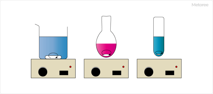
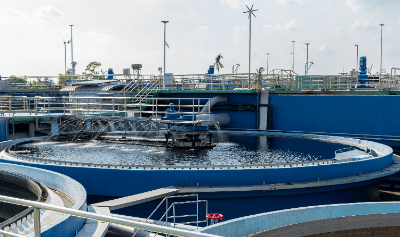
Figure 1. Image of a stirrer

A stirrer is a laboratory instrument made of small magnets used to stir liquids.

It is sometimes called a stirrer bar, stirrer tip, or rotor. The most common way to use a stirrer is to place a container containing a stirrer on top of the magnetic stirrer and rotate the stirrer. The stirrer in the container rotates with the movement of the magnets in the magnetic stirrer, thereby stirring the liquid.

Uses of Stirrers

Magnetic stirrers are used in chemistry, biology, pharmacy, medicine, and all other fields of experimentation, development, and analysis that require the stirring of liquids.

They have the advantage of being more efficient than simple bar magnets themselves. They are also easier to use than gear-driven electric stirrers because they have no moving external parts to break or wear out. To achieve good stirring conditions, it is important to fine-tune the speed of the magnetic stirrer.

However, it is difficult to handle viscous liquids or thick suspensions, and stirrers of different shapes and sizes should be used to stir larger volumes or more viscous liquids.

Principles of Stirrers

3787_Stirrers_撹拌子-2.png

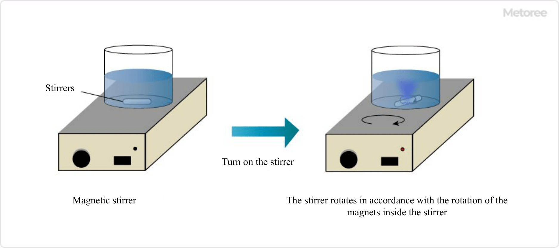
Figure 2. How to use the stirrer

Stirrers are usually used in combination with a magnetic stirrer. The mechanism by which the magnetic stirrer and stirrer agitate the liquid in the container is as follows:

  1. Place the liquid and stirrer in the stirrer container and place it on top of the magnetic stirrer.
  2. There is a magnet inside the magnetic stirrer, so the stirrer and the magnet inside the magnetic stirrer attract each other.
  3. When the magnetic stirrer is turned on, the magnet inside the magnetic stirrer begins to rotate, and the stirrer rotates with it.
  4. The rotation of the stirrer stirs the liquid.

Because the stirrer is small, it can be cleaned and sterilized more easily than other devices or stirring rods. However, when mixing viscous liquids or thick solutions, it is preferable to use a different stirring method because the stirring force may not be sufficient.

A container that does not require complicated sealing or other conditions and does not affect magnetism can be used. Typically, it is used in laboratory glassware, such as vials or beakers.

Also, stirrers are usually coated with Teflon or glass and are chemically inert. They will not contaminate or react with the mixture during mixing.

Types of Stirrers

3787_Stirrers_撹拌子-3.png

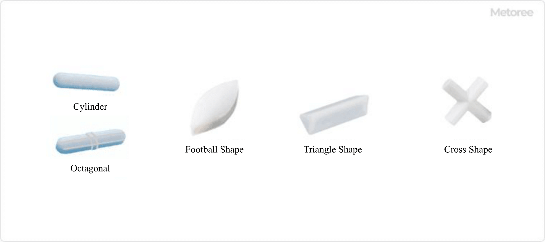
Figure 3. Various stirrers

The stirrer’s stirring power depends on the liquid being stirred and the shape of the container. Various shapes are commercially available, ranging in size from a few millimeters to several centimeters.

1. Rod-Shaped Stirrer

This is the most commonly used and common stirrer. It is used to agitate containers with flat bottoms, such as beakers.

2. Football-Shaped Stirrer

This stirrer is tapered like a football. The tapered structure enables smooth stirring in round-bottom flasks and eggplant flasks.

3. Octagonal Stirrer

It is characterized by its octagonal cross section and a central band for rotation. The central band prevents the agitator from hitting the container during stirring.

4. Triangle-Shaped Stirrer

This stirrer has a triangular cross section. It has strong stirring power and is used for stirring liquids containing sediments or liquids with strong viscosity.

5. Cross-Shaped Stirrer

This stirrer is cross-shaped when viewed from above. The cross-shaped agitator can create a vortex when stirring, thus possessing strong stirring power.

How to Select Stirrers

Stirrers are selected according to the quantity and condition of the material to be stirred, the container to be used, and the power of the stirrer’s motor. Although there are many different types of stirrers available, it is recommended that you clarify the purpose of your use and use the information in the stirrer specifications as a guide in making your selection.

The following are examples of magnets used in stirrers:

1. Neodymium Magnet

This magnet is made by sintering neodymium, carbon, and boron together. It exhibits high magnetism among permanent magnets. The disadvantages are its high price and the fact that its magnetism changes with temperature; it should be used at 80 °C or lower.

2. Ferrite Magnet

This magnet is made by sintering iron oxide and barium together. Not only does it exhibit stable magnetism, but it is also inexpensive. These magnets are easy to use for large objects.

3. Samarium-Cobalt Magnet

This magnet is made by combining samarium and cobalt. Because it uses a rare metal, it is even more expensive than neodymium magnets. It is sometimes used as a material for Stirrers because its magnetism is stable even at high temperatures.

4. Rare Earth Magnets

Manufactured by sintering neodymium, boron, and iron, these magnets have the best magnetic properties. Due to their low temperature characteristics, they must be used at temperatures below 80°C. It is used as a strong magnetic stirrer or a super strong magnetic stirrer.

Other Information on Stirrers

1. Prevention of Contamination by the Stirrer

The stirrer is a device that can easily cause contamination. After removal from the solution, they should be cleaned by an appropriate method that removes the solution used.

Before use, make sure the surface is clean and discard any with yellowing.

2. Removal of the Rotor

After using the rotor, remove it by placing a magnet against it from outside the container or by using a rod made of magnets. After removing the rotor, do not touch it carelessly and wash it.

カテゴリー
category_usa

Friction Testers

What Is a Friction Tester?

A friction tester is a device designed to measure various frictional forces.

Friction is a resistance force that occurs when two objects are in contact. There are two main types of friction forces: static and kinetic. Static friction acts on a stationary object, while kinetic friction affects an object in motion. The coefficient of static friction evaluates the resistance to movement or slippage of a stationary object. Conversely, the coefficient of kinetic friction, which represents the frictional force between moving objects, assesses how slippery or worn an object is during motion.

Uses of Friction Testers

Friction testers are instrumental in inspecting and evaluating the performance of various materials and products.

1. Evaluation of Materials

For example, the evaluation of rubber and plastic, commonly used as shock absorbers and safety devices, requires measuring their friction force to assess their durability and safety.

2. Evaluation in the Automotive Field

These testers are essential for evaluating the durability of painted surfaces on automobiles. They help ensure that these surfaces are sufficiently resilient to friction and resistant to scratching and peeling.

3. Evaluation in the Field of Construction Materials

Friction testers also play a significant role in assessing coatings on building materials. They measure the slipperiness of wooden floors and the scratch resistance of paints and other coatings.

4. Evaluation in the Medical Field

In the medical sector, these devices are used for measuring the friction of artificial joints and injection needles.

Principle of Friction Tester

Friction testers measure either the “coefficient of static friction” or the “coefficient of kinetic friction,” corresponding to the two types of frictional forces: static and dynamic.

1. Static Friction Coefficient Measurement Type

This type determines the coefficient of static friction, often used for materials like paper and plastic film. The inclined method involves placing weights on the sample and tilting it until the weight begins to slide. The angle at this point is used to calculate the coefficient. The horizontal method, where a weight is placed on the sample and pulled, measures the resistance at the point of movement.

2. Coefficient of Dynamic Friction Measurement Type

Specialized testers for kinetic friction slide a specified material on the sample. They come in rotational and reciprocating types. Measurements are made using various methods, including direct force measurement with a strain gauge or load cell, or calculating based on the load power of the drive motor.

Types of Friction Testers

The main types for measuring dynamic friction are rotating and reciprocating testers, available in point, line, and surface contact forms.

1. Point Contact Type

Examples include ball-on-plate and ball-on-disk methods, where a spherical material interacts with a disk or plate sample. These methods are straightforward due to the point of contact but can be inaccurate if the balls or pins wear down.

2. Linear Contact Type

The block-on-ring and pin-block methods involve a block or pin-shaped sample interacting with a cylindrical material. These are predominantly used for rotating types and are particularly useful for measuring lubricating materials.

3. Surface Contact Type

These include block-on-plate, pin-on-disk, and thrust cylinder types. The pin or cylinder in these methods interacts with a flat sample surface. The block-on-plate method is a reciprocating type, while the pin-on-disk and thrust cylinder methods are rotating types. The advantage of surface contact types is their larger contact area, providing increased durability.

カテゴリー
category_usa

Stress Analyzers

What Is a Stress Analyzer?

A stress analyzer is an instrument used to determine the type of stress applied to a material.

There are several types of stress-measuring machines, each designed for specific purposes. This section broadly describes stress-measuring machines. Stress can be compressive or tensile. Excessive stress, whether compressive or tensile, can cause component damage. In addition to stresses from external mechanical forces, materials can also experience residual stresses due to processes like heat treatment or film formation.

Reinforcing materials like glass or steel can increase a product’s strength by intentionally creating residual compressive stress on the surface.

Uses of Stress Analyzers

Stress analyzers are employed in various fields, ranging from product development to heat treatment, film deposition, and glass strengthening. In research and development, these analyzers are utilized to assess component strength by determining the stress they endure and to optimize designs by reducing unnecessary material, thereby cutting weight and costs.

In the semiconductor industry, stress measurement is crucial for quality control, as various thin films are deposited on silicon wafers. Excessive stress can lead to film peeling.

Moreover, in glass tempering processes, stress measurement is conducted after the strengthening process to ensure increased compressive stress near the surface, enhancing the glass’s strength.

Principle of Stress Analyzers

The principle of a stress analyzer varies based on the measurement method. However, all analyzers detect the strain in the material under test. Strain refers to the stretching, shrinking, twisting, or deformation of a material under external force.

Stress is defined as force per unit area and is calculated by multiplying the material’s strain by its Young’s modulus. Therefore, stress analyzers indirectly measure stress by capturing the strain caused by external forces on a material and converting this data into stress values using Young’s modulus.

There are various methods for detecting strain, and stress analyzers are developed based on these different principles.

Types of Stress Analyzers

Stress analyzers come in various types, suited to the specific material and stress magnitude to be measured. Here are four typical examples:

1. Strain Gauges

Strain gauges are primarily used to measure stress in structural components. They detect strain through changes in electrical resistance. Strain gauge-based stress measurement is specific to the part where the gauge is attached.

These gauges are often used in conjunction with CAE for structural analysis verification.

2. Infrared Detection

Infrared stress measurement is another method for structural components. Material deformation due to external forces leads to surface temperature changes, a phenomenon known as thermoelastic effects.

This method involves detecting stress from temperature changes on the material’s surface due to strain. Unlike strain gauges, infrared stress measurement can assess a broader area.

3. Laser Beam Reflection

Laser light reflection is used for stress measurement in thin film deposition. Changes in the radius of curvature, due to substrate warping after deposition, are determined by comparing laser light reflection before and after deposition, thereby assessing film stress.

This technique is also used in evaluating semiconductor silicon wafers and tempered glass.

4. X-Ray Diffraction

X-ray diffraction measures residual compressive stress caused by heat or surface treatment of materials like steel. It utilizes the diffraction of X-rays scattered by irradiating materials with X-rays of a wavelength similar to the distance between atoms in a regularly arranged atomic structure.

Beyond stress measurement, X-ray diffraction is also used for material analysis, including qualitative and quantitative analysis, crystal size calculation, and lattice distortion assessment.

カテゴリー
category_usa

Circulating Pumps

What Is a Circulating Pump?

Circulating pumps are used for moving liquids in various settings, ranging from small-scale applications like home tropical fish tanks to large-scale uses such as water purification tanks. These pumps are essential in urban infrastructure, ensuring the movement and recirculation of liquid from storage tanks to filtration systems and other destinations.

Uses of Circulating Pumps

Circulating pumps have diverse applications across household and industrial settings. Key uses include:

  • Cooling water circulation in cooling towers
  • Chemical circulation in scrubbers
  • Pure water circulation in water-tube boilers
  • Water storage and filtration in swimming pools
  • Pumping mineral spring water in spas
  • Aquaculture water tanks
  • Water filtration systems
  • Dialysis and artificial heart systems

Principles of Circulating Pumps

Most circulating pumps are electric motor pumps, often incorporating centrifugal pumps. Components include the impeller, casing, and rotating shaft. The motor-driven shaft rotates the impeller, creating pressure to move liquid. Besides centrifugal pumps, piston and diaphragm pumps are also used.

Types of Circulating Pumps

Different types of circulating pumps are designed for specific applications:

  • Piston Pump: Uses a piston to drive valves, suitable for high-pressure applications.
  • Diaphragm Pump: Moves a diaphragm to create pressure, known for low leakage risk. Air-powered versions are available.
  • Volute Pump: A centrifugal pump variant, ideal for circulating large volumes of liquid.

Other Information on Circulating Pumps

1. Selecting Circulating Pumps for Hot Water Heating

Important factors include head (the height the pump can elevate water) and flow rate. These determine the pump’s suitability for heating systems, considering piping resistance and heat output requirements.

2. Relationship Between Heat Exchangers and Circulating Pumps

Circulating pumps are often paired with heat exchangers in systems like air conditioners and water heaters. The pump size is chosen based on the heat exchanger’s required flow rate and pressure.

3. Circulating Pumps in High-Rise Buildings

In tall buildings, pressurized circulating pumps are used to move water from storage tanks to upper floors. For buildings with many floors, intermediate pumps may be used to maintain pressure.

カテゴリー
category_usa

Wastewater Treatment Equipment

What Is Wastewater Treatment Equipment?

Used Wastewater Treatment Equipment

Wastewater treatment equipment is designed to treat wastewater containing oil, acids, alkalis, or other harmful components.

Wastewaters often contain hazardous material contaminants that can have detrimental effects on the environment and human health if left untreated. Wastewater treatment equipment employs various technologies to remove or neutralize these hazardous contaminants.

However, since the composition and types of hazardous substances in wastewater can vary significantly, it is crucial to select the appropriate equipment based on the specific characteristics of the wastewater and its intended purpose.

Applications of Wastewater Treatment Equipment

Wastewater treatment equipment finds application in a wide range of industries and facilities, with a significant presence in industrial and chemical processes.

1. Factories and Manufacturing Facilities

Factories and manufacturing facilities often generate wastewater as a byproduct of their production processes. This wastewater, in the form of effluent, needs treatment to remove harmful substances and contaminants, minimizing its environmental impact.

2. Chemical Industry and Research Laboratories

In the chemical industry and research laboratories, chemical reactions and experiments frequently result in wastewater generation. These effluents may contain hazardous chemicals and organic solvents, necessitating the use of wastewater treatment equipment to eliminate harmful components.

3. Food Processing Industry

The food processing industry also produces wastewater from its production lines and cleaning processes. Proper wastewater treatment is essential to purify these wastewater and ensure compliance with environmental standards.

Principle of Wastewater Treatment Equipment

Wastewater treatment equipment employs various principles and technologies to remove or neutralize toxic substances and contaminants present in wastewater. One common method is combustion treatment, which detoxifies liquid waste by incinerating it. This method is widely utilized in industries such as petrochemicals and paper manufacturing.

Another prevalent approach involves the physical removal of contaminants, achieved by separating solids and suspended solids from the wastewater. This is accomplished using equipment such as filtration systems and centrifuges, capable of removing minute solid particles and insoluble materials.

Chemical reactions are also harnessed to break down toxic substances within liquid waste. Sedimentation tanks and sedimentation processes are employed to purify liquid waste by allowing heavy solids and insoluble substances to settle. Distillation units facilitate the separation of liquid waste by vaporization and condensation, allowing the recovery of pure components while removing solutes and contaminants.

Types of Wastewater Treatment Equipment

There are various types of wastewater treatment equipment. The following are some examples:

1. Filter Press

A filter press is a piece of equipment that separates solids by subjecting pressurized liquid waste to filtration. The liquid waste is forced through filter plates, compressing solids into a solid form under pressure. This process effectively separates liquid waste into solid and liquid components.

2. Centrifuge

This device utilizes high-speed rotation to separate solids from liquid waste through centrifugal force. The liquid waste is pressed against the inner wall of a rotating drum by centrifugal force, causing heavier solids to accumulate inside the drum. The clean liquid is discharged from the drum’s exterior.

3. Thickener

Thickeners are used to facilitate the settling of solids and insoluble substances in liquid waste. Gravity causes solids to settle at the bottom, and the purified supernatant liquid is discharged. Settled solids are typically collected and may undergo further treatment or disposal.

4. Distillation Unit

Distillation units are employed to separate and refine liquid waste components by vaporizing and recondensing the liquid. Volatile components are evaporated by heating the liquid waste and subsequently condensed to obtain pure components. This process effectively removes solutes and contaminants from the liquid waste.

Other Information on Wastewater Treatment Equipment

1. Types of Wastewater

Wastewater is broadly classified into organic and inorganic waste liquids.

Organic Waste Liquids
Organic wastewater can be further categorized into five types: “specified toxic organic solvents,” “photographic developing wastewater,” “photographic fixing wastewater,” “flammable wastewater,” and “nonflammable wastewater.” Organic waste liquids can originate from various sources, including home cameras, motion picture film, and x-rays. Treatment methods for organic waste liquids often involve combustion and biological treatment.

Inorganic Waste Liquids
Inorganic waste liquids are also categorized into five types: cyanide waste liquids, mercury waste liquids, fluorine and phosphate waste liquids, heavy metal waste liquids, and acid and alkaline waste liquids. Treatment of inorganic wastewater typically includes neutralization, activated sludge processes, and coagulation-sedimentation treatments.

2. Regulations for Wastewater Treatment Equipment

The installation and management of wastewater treatment equipment must comply with the regulations set forth by the Ministry of Health, Labor, and Welfare. Standards for the installation of wastewater treatment equipment are required whenever inorganic wastewater is handled.

In wastewater treatment equipment, drains and pits mustn’t mix with effluents containing hydrochloric acid, nitric acid, or sulfuric acid and those containing potassium cyanide, sodium cyanide, or sodium sulfide. Mixing produces toxic hydrogen cyanide or hydrogen sulfide. Wastewater treatment equipment must be subject to periodic voluntary inspections once a year, and records of these inspections must be kept for three years.