カテゴリー
category_usa

Voltage Relays

What Is a Voltage Relay?

A voltage relay is a device that detects voltage changes in an electric circuit and transmits them to another circuit or device.

Its main purpose is to detect voltage fluctuations and abnormalities in power and control systems, controlling and protecting systems accordingly. Voltage relays typically transmit signals through electrically isolated circuits to enhance electrical safety and ensure insulation between different circuits.

These devices are crucial in high-voltage environments due to their high measurement accuracy and reliable operation. Their design allows for precise detection and response to specific voltage values.

Uses of Voltage Relays

Voltage relays are employed in various applications, particularly in power transmission, distribution, power generation, and substations.

1. Power Systems

In power systems, voltage relays protect against abnormal voltages by detecting overvoltage or undervoltage situations and either shutting down electricity or monitoring power quality.

2. Transformers

Transformers use voltage relays to maintain proper voltage levels. Some transformers, equipped with tap-switchers, adjust output voltage automatically in response to supply voltage variations and power demand, as detected by voltage relays.

3. Generators

For generator safety and proper operation, voltage relays detect fluctuations or abnormalities, regulating voltage or interrupting circuits as needed. They are essential for controlling synchronous equipment and preventing overvoltage, undervoltage, and reverse power issues.

Principle of Voltage Relays

Voltage relays measure voltage through instrument transformers or similar devices. The input electrical signal is processed by a transformer circuit or similar device, which amplifies or modulates the signal to an appropriate level, adjusting its strength and range.

The processed signal is then converted to an analog or digital output, used for control or signaling purposes. In some designs, voltage relays are isolated between input and output circuits, using insulating materials and transformers for safety and circuit independence.

Types of Voltage Relays

Various types of voltage relays exist, each serving specific functions:

1. Overvoltage Relay

An overvoltage relay activates when the voltage in a power system exceeds a specified range, generating a control signal to shut down the circuit or alert the controller, preventing equipment damage and overloads.

2. Undervoltage Relay

An undervoltage relay operates when the voltage drops below a set level, triggering a control signal to interrupt the circuit or signal a controller. It is crucial for preventing issues caused by undervoltage in power systems and ensuring the activation of backup power supplies.

3. Ground Fault Overvoltage Relay

A ground fault overvoltage relay responds to ground faults in a power system, detecting overvoltage due to ground faults and preventing equipment damage and electrical accidents. However, it’s often used alongside ground fault direction relays and overcurrent overcurrent relays for comprehensive protection.

カテゴリー
category_usa

Voltage Regulators

What Is a Voltage Regulator?

Voltage Regulators

A voltage regulator is a device that can adjust its voltage output to any desired value. It is used for high-precision voltage variation in various applications.

Voltage regulators are commonly employed to provide variable voltage according to the specific voltage requirements of facilities in factories or buildings.

There is a wide range of voltage regulators available from power supply equipment manufacturers, and it is crucial to select one that fits the operating environment and intended equipment uses and purposes.

The demand for voltage regulators in the telecommunications equipment industry has been increasing, particularly due to the advent of 5G technology.

Uses of Voltage Regulators

Voltage regulators, featuring variable output voltage, consist of a toroidal transformer, sliding brushes, and a sliding mechanism. They are used for generating any required voltage.

Currently, voltage regulators can be categorized broadly into two types. The appropriate type should be chosen based on the purpose of use and the operating environment.

The categories of voltage regulators are listed below:

  • Sliding Type Voltage Regulator: Consists of a toroidal transformer, sliding brushes, and a sliding mechanism.
  • Semiconductor Type Voltage Regulator: Characterized by having a transformer mechanism with elements in a semiconductor substrate.

Although more compact than the sliding type, there is a risk of damage due to noise, etc.

Principles of Voltage Regulators

The voltage generator varies the output voltage by means of a toroidal transformer mounted in the equipment and a sliding brush and sliding mechanism.

The input voltage can be immediately varied to any desired value and output after operation with a touch panel or incidental switch.

Voltage regulators are mainly classified into four types: single-phase 100 V, single-phase 200 V, three-phase 200 V, and three-phase 400 V. They are used for different purposes.

The main features are described below:

  1. Input voltage variable from 100V to 440V and output
  2. Unlike power supplies that use semiconductors, they are resistant to instantaneous over-currents

When using a voltage regulator, it is necessary to decide whether it will be used for DC or AC applications. Then select the type of power converter that best suits the purpose of use and the environment in which it will be used.

Since each manufacturer has various characteristics, it is important to adjust the voltage to the appropriate voltage and supply the voltage after differentiating between different types of voltage regulators according to the intended use.

カテゴリー
category_usa

Electric Furnaces

What Is an Electric Furnace?

Electric Furnaces

An electric furnace is a testing equipment used to heat, melt, or burn test specimens such as metals, glass, ceramics, and semiconductor parts by heating a built-in heater (heating element) to a high temperature inside the chamber using electrical power.

They are used for various testing purposes, including the development of new materials, chemical material analysis, combustion testing, and heat resistance testing.

The maximum temperature that can be set inside an electric furnace varies depending on the product, but generally ranges from around 1,000°C to 3,000°C.

Uses of Electric Furnaces

In addition to electric furnaces with high-temperature settings, there are also vacuum furnaces that can create a near vacuum inside the chamber.

Another type is the rotary kiln, which automatically rotates the sample placed in the chamber to provide even heating. This kiln also includes a mechanism for the automatic loading and unloading of samples.

Various types of heating elements are used as heaters.

For example, iron nichrome and Kanthal wire are heating elements used for temperatures up to about 1300°C, while silicon carbide heating elements are used up to about 1500°C. Molybdenum disilicide can be used up to about 1800°C, and carbon (graphite) heaters are suitable for temperatures up to about 3000°C.

Principles of Electric Furnaces

The interior of an electric furnace comprises a heater and insulation material. Additionally, a control system is incorporated to set and maintain the temperature inside the chamber.

The control system operates as follows:

First, the desired temperature is set by operating switches while monitoring the control panel. Once the temperature is set, the electric furnace’s control microcomputer begins the temperature control process to reach and maintain the target temperature.

Some electric furnaces allow programming to set temperature A, maintain it for t1 hours, then set temperature B, maintain it for t2 hours, and so on.

To control the temperature inside the furnace, the control microcomputer periodically reads temperature data from the temperature sensor inside the chamber. If the current temperature is lower than the set temperature, the heater continues heating. If the current temperature exceeds the set temperature, the heater stops heating. This temperature control process is repeated to maintain the desired temperature.

Generally, the PID control method is used for precise temperature control inside the furnace.

カテゴリー
category_usa

Electronic Timers

What Is an Electronic Timer?

An electronic timer, also known as a program timer, is a device capable of automatically turning on and off an electrical appliance at specific times. Electronic timers have been in use for quite some time.

In general, electronic timers are used to schedule the activation and deactivation of electrical devices at consistent times each day.

For instance, pattern A might control the ON/OFF schedule for a Monday, while pattern B handles Tuesday, and so on with patterns C, D, E, and others, allowing users to select a program for each day of the week. Various types of electronic timers are available to suit these needs.

Uses of Electronic Timers

Electronic timers find applications in lighting fixtures and household appliances.

For example, a lighting fixture can be programmed to turn on and off at specific times each day, or a humidifier can be scheduled to activate and deactivate, such as at bedtime.

Beyond these basic functions, modern electronic timers come equipped with various additional features. Some incorporate brightness sensors to activate devices when the surroundings are well-lit and deactivate them in darkness, ideal for daytime use.

There are also waterproof models designed for outdoor use and timers that display the power consumption of connected devices.

Electronic timers are available in a wide price range, from affordable models starting at around 1,000 yen to more advanced models exceeding 10,000 yen.

Principles of Electronic Timers

Electronic timers are equipped with an AC outlet on the power supply side that accepts 100 VAC commercial power and an AC outlet on the power take-off side for the electrical device to be controlled.

When the specified ON time is reached, the power supply side and power take-off side are connected, allowing power to flow to the connected device.

The mechanism is straightforward: when the designated ON time arrives, the electronic timer connects the power supply and power take-off sides, supplying power to the connected device.

The allowable power capacity varies depending on the type of electronic timer. It is essential to check the timer’s permissible capacity and ensure that the connected device’s power requirements are within the allowable limit before use.

Simple electronic timers, designed to turn on and off at specific times each day, often rely on basic logic circuits. In contrast, highly functional electronic timers with multiple programs, operational buttons, and LCD displays are frequently designed using single-chip microcomputers.

カテゴリー
category_usa

Leaf Blowers

What Is a Leaf Blower?

A leaf blower is a blower powered by an electric motor.

Leaf blowers, typically hand-held power tools, are used for cleaning and drying by blowing powerful air.

They can clean various objects, from sand and fallen leaves to wood and metal shavings. Additionally, they are used for draining and drying tasks, such as blowing away water droplets after washing a car.

Most models allow users to set wind power and speed, adjusting them as needed. Besides blowing, many leaf blowers also feature a suction function, useful for collecting fallen leaves and debris.

Uses of Leaf Blowers

Leaf blowers serve multiple purposes:

1. Yard and Lawn Cleanup

For yard and lawn cleanup, leaf blowers remove fallen leaves and dead grass, enhancing aesthetics and lawn health. They are also efficient in cleaning large public areas and parks.

2. Equipment Cleaning

They are commonly used for cleaning outdoor equipment, like air conditioners, by unclogging dust and leaves from exhaust vents, thus promoting efficient operation.

Principle of Leaf Blowers

Leaf blowers consist of several key components:

1. Motor

The motor, powered by a battery or electrical outlet, produces rotary motion. DC motors are common in battery-powered models, while AC motors are used in corded versions.

2. Fan

The fan, attached to the motor’s shaft, accelerates ambient air, creating a high-velocity breeze through the blower’s nozzle.

3. Nozzle

The nozzle directs the airflow. Adjustable nozzles can alter wind patterns for different areas.

4. Handle

Handles, often with an on/off switch, aid in the operation and control of the blower.

5. Power Supply

The power supply, either a built-in battery or a power cord, powers the motor. Battery models offer portability but require recharging, while corded models allow continuous use within the cord range.

How to Choose a Leaf Blower

Consider the following when selecting a leaf blower:

1. Air Volume and Speed

Select a blower based on the required wind speed and volume, which are key for different cleaning areas.

2. Weight

Lightweight leaf blowers are preferable for extended use to prevent fatigue. Additionally, the handle’s design and grip comfort are important for ease of operation.

3. Power Supply

Choose between battery-powered or power-cord models based on mobility needs and usage duration. Battery types offer flexibility but have limited working hours, while corded types provide continuous operation within the cord’s range.

カテゴリー
category_usa

Continuity Testers

What Is a Continuity Tester?

A continuity tester is a testing device used to connect various cables, harnesses, and connectors for the purpose of verifying electrical connectivity. It rapidly checks whether cables and other components are electrically connected as expected at both ends.

Typically, the tester is housed in a compact chassis and features an LCD panel on the front, a lamp for displaying test results, a start button, and buttons for configuring test parameters. On the back, you will find connectors for attaching the cables to be tested.

Additionally, on the rear side, there are several connector terminals designed for connecting cables. Some testers also have the capability to print test results using a printer.

It is worth noting that while these devices are commonly referred to as “continuity testers,” we will specifically focus on the types of testers mentioned above.

Uses of Continuity Testers

Continuity testers can be controlled from a PC, allowing for detailed configuration of test parameters and test item control, which helps streamline preparation and reduce overall testing time.

Some continuity testers are capable of simultaneously testing cables, harnesses, and connectors with 100 or more pins, further enhancing their efficiency.

These testers verify correct wiring between terminals, including cables and connectors, by applying a relatively low voltage and measuring the resulting current flow between the terminals.

Principles of Continuity Testers

In addition to the previously described continuity testing, certain continuity testers are equipped to perform withstand voltage testing, insulation resistance testing, and instantaneous disconnection testing.

Withstand voltage testing evaluates the insulation between terminals by applying a reduced voltage between different terminals and checking for any sparks or other abnormal phenomena.

Insulation resistance tests ensure that the insulation resistance between terminals meets the specified requirements for cables and connectors.

The instantaneous disconnection test is conducted while cables and connectors are placed in specific positions during the normal continuity test. This test can detect momentary disconnections, even if the pins in the connector are poorly soldered or if the cable is partially damaged, by applying vibrations to the cable or connector.

As explained earlier, some continuity testers integrate continuity testing with withstand voltage testing, insulation resistance testing, and instantaneous disconnection testing. These tests are programmable on the PC side and can be performed automatically and sequentially.

The test procedure, configured on the PC, is transmitted to the device. Once the setup is complete, the cable or connector to be tested is connected to the continuity tester, and the tests are executed sequentially.

カテゴリー
category_usa

Conductive Tapes

What Is a Conductive Tape?

A conductive tape is a type of tape that possesses conductive properties.

It is typically made from materials like aluminum or copper foil or contains conductive fillers, such as metal particles, within its adhesive layer. Conductive tape is known for its low electrical resistance. Given the variety available, choosing the right type of conductive tape for a specific application is crucial. Consider factors such as strength, flexibility, and whether a single-sided or double-sided adhesive is required.

This tape is often employed to shield equipment from external electromagnetic and electrostatic interference. It is applied near sources of noise or onto the surfaces of semiconductor devices.

By connecting one end of the conductive tape directly to the device’s ground line, it serves to absorb and dissipate external noise through the ground line, effectively safeguarding the equipment.

Applications of Conductive Tapes

1. Static Electricity and Electromagnetic Shielding

3906_Conductive-Tapes_導電テープ-1.png

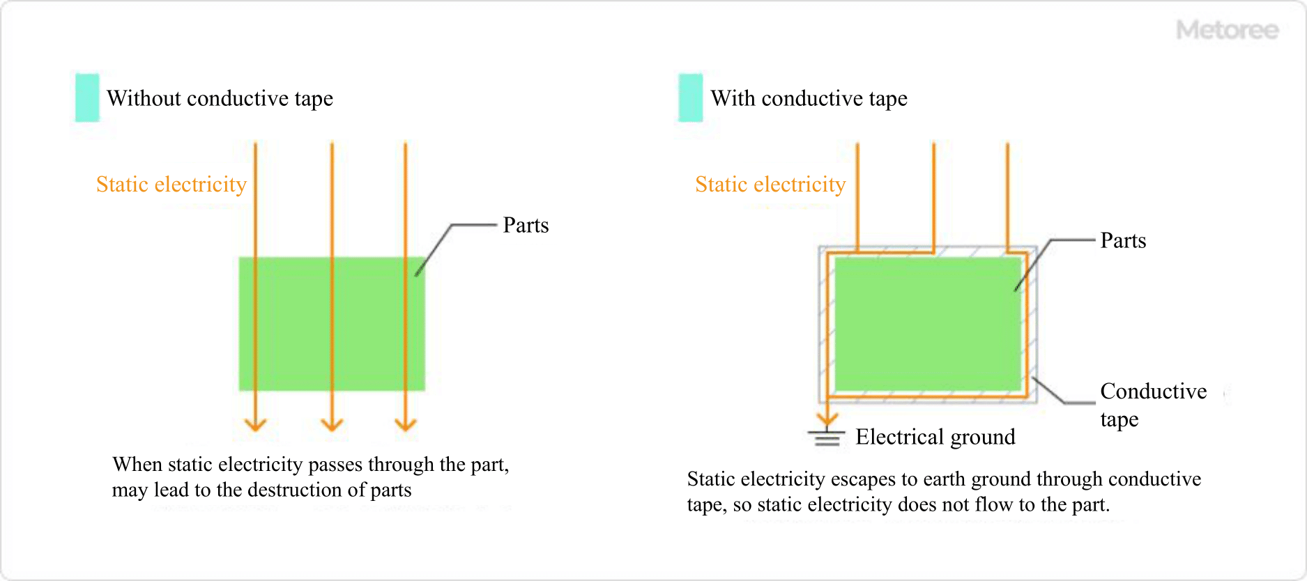
Figure 1. Protection of components using conductive tape

In a factory environment, a worker touching a product charged with static electricity can potentially damage semiconductor components on the electronic board inside the product, or even lead to partial destruction in the worst-case scenario.

To prevent such situations, measures like laying down conductive mats within the factory are necessary. These mats allow static electricity to flow from the product enclosure’s surface to the conductive mat on the worktable, grounding it in the process.

However, depending on the route static electricity takes into the equipment, it may reach the printed circuit board inside the product. In such cases, conductive mats alone may not suffice, and measures must be taken on the board level. Conductive tape is used to protect individual components by insulating them from static electricity and connecting them to the ground line.

2. Electrical Distribution Safety Measures

Conductive tape also serves as a safety measure in the distribution of electricity generated at power plants to offices and homes. While insulating tape is typically used to insulate cables from electricity, semi-conductive tape with slightly higher resistance is used in certain situations.

Cables containing a conductive layer can experience electric field concentration at specific points in the conductive layer if left unconnected when attached. Wrapping semi-conductive tape around the conductive layer helps alleviate this electric field stress.

3. Analytical Applications

3906_Conductive-Tapes_導電テープ-2.png

Figure 2. Role of conductive tape in SEM

When observing samples with a scanning electron microscope (SEM) or transmission electron microscope (TEM), commonly used in R&D applications, it is necessary to ensure that the sample is conductive. Conductive tape is applied to both sides of the specimen when it is placed on the observation table to provide a discharge path for irradiated electrons and prevent specimen charging during observation.

Principles of Conductive Tapes

3906_Conductive-Tapes_導電テープ-3.png

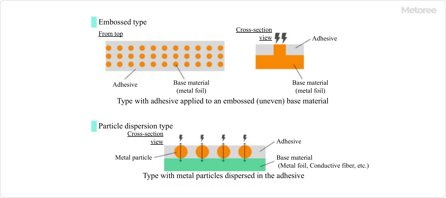
Figure 3. Structure principle of conductive tape

Conductive tape, like regular adhesive tape, consists of a base material and an adhesive. An adhesive is applied to embossed metal foil to impart conductivity, or metal particles are dispersed within the adhesive.

In addition to metallic foil, conductive tapes occasionally use conductive fibers with excellent flexibility as base materials. Conductive tapes with conductive fibers are often preferred for applications in moving or narrow equipment areas.

Types of Conductive Tapes

Among conductive tapes, there are specialized types like conductive carbon tape and transparent conductive tapes, designed for specific electronic equipment applications beyond just antistatic purposes.

1. Conductive Carbon Tape

Conductive carbon tape utilizes aluminum as the primary metal foil and incorporates a conductive filler of carbon powder within its adhesive layer. This results in the tape’s characteristic black color.

Conductive carbon tape is often used as a double-sided tape with adhesive layers on both sides of the metal foil. It finds application in scanning electron microscopy (SEM) observation and is suitable for analytical applications due to its minimal or absence of gas emission.

2. Transparent Conductive Tape

Some transparent conductive tapes are used in cleanroom environments. Products lacking anti-static measures are unsuitable for cleanrooms as they attract dust and contaminants, posing a risk to the controlled environment.

One example consists of a polybutylene terephthalate resin (PET) base material with a poly-conductive layer and an acrylic adhesive on the external side of the layer. These transparent conductive tapes offer excellent conductivity and transparency, making them ideal for highly adhesive electronic tape applications used in packaging static-sensitive components. They also function as adhesive tapes with anti-static specifications to mitigate peel-off charging.

Furthermore, they are employed as electrostatic chucks for CMOS, MEMS, power devices, and glass wafers in plasma and CVD processes.

Additional Information on Conductive Tapes

1. Mitigating Static Noise

Conductive sheets and tapes are used to prevent equipment damage caused by static electricity. Static electricity poses a significant challenge in factories, as it can potentially lead to component damage on internal circuit boards, even if unnoticed until product shipment.

To address this, it is crucial to implement local countermeasures using conductive tape in conjunction with broader approaches, such as the following:

  1. Increase Humidity in the Factory: Maintaining a constant humidity level within the factory helps reduce electrical resistance on equipment surfaces.
  2. Provide Grounding Wires: Supply workers with grounding wires for their wrists and other body parts to prevent static electricity generation.
  3. Lay Conductive Sheets: Use conductive sheets to provide a discharge path for static electricity, even if a worker becomes charged.
  4. Apply Conductive Tape to Equipment: Protect equipment by affixing conductive tape near potential noise entry points and on semiconductor device surfaces.

2. Solderable Conductive Tape

Metal conductive tapes, such as copper foil tape and aluminum foil tape, are developed for soldering to metal foil surfaces to establish electrical connections with other components. Conductive tapes, featuring adhesive properties, are easily applied to objects and are suitable for wiring work involving soldering.

カテゴリー
category_usa

Copper

What Is Copper?

Copper

Copper, with the atomic number 29 and symbol Cu, is widely used in electrical wiring, electronic components, generators, solar cells, and coolers due to its excellent electrical and thermal conductivity. It has a relatively low melting point, allowing for easy molding into various shapes.

Being rust-resistant and chemically stable, copper is highly durable and thus extensively used in construction materials, ships, automobile parts, water pipes, heaters, and coolers. Copper oxide, which forms on its surface, has antibacterial properties, making copper suitable for food processing and medical equipment.

Uses of Copper

Copper is used in various applications, including:

  1. Electrical and electronic equipment: Wiring, circuit boards, motor and transformer coils, etc.
  2. Building and construction materials: Exterior walls, roofing materials, building interiors, doorknobs, handrails, etc.
  3. Automobile and ship parts: Engine parts, cooling system pipes, ship propellers, electrical wiring, etc.
  4. Medical equipment: Surgical tools and medical equipment surfaces, etc.
  5. Food processing and cooking utensils: Pots, pans, oven dishes, etc.
  6. Manufacturing: Copper sheets, machine parts, pipes, building materials, etc.

Types of Copper

There are various types of copper, including alloys:

1. Oxygen-Free Copper

Copper purified by removing oxygen, enhancing its electrical conductivity, making it preferred for electrical wiring and electronic components.

2. Tough Pitch Copper

Strengthened copper containing small amounts of impurities like copper oxide and copper iron, which increase its strength through a fine crystalline structure.

3. Copper Phosphate

Copper treated with phosphoric acid to enhance electrical conductivity and corrosion resistance by removing impurities.

4. Other Alloys

Includes bronze, white copper, nickel silver, brass, aluminum bronze, titanium copper, and chrome copper.

Properties of Copper

1. Thermal Conductivity

One of the best metals for thermal conductivity, copper quickly and evenly transfers heat, reducing temperature disparities.

2. Electrical Conductivity

Excellent at conducting an electric current, copper is vital for efficient transmission in electrical circuits and reduces the loss of electrical signals and power.

3. Nonmagnetic

Pure copper is nonmagnetic due to its atomic structure and electron configuration. However, its magnetism can vary in copper alloys or when impurities are present.

4. Corrosion Resistance

Copper is highly resistant to corrosion and oxidation, attributed to the self-healing oxide film that forms on its surface.

5. Malleability and Ductility

Copper is both malleable and ductile, enabling it to be easily reshaped when heated and to elongate under tensile force due to its crystalline structure.

6. Alloying Capability

Copper readily forms alloys with other metals, such as brass (copper and zinc) and copper-nickel alloys, which have varied properties like electrical and thermal conductivity, corrosion resistance, and strength.

Other Information on Copper

Additional Properties of Copper

Copper also exhibits:

Weldability: Suitable for welding operations due to excellent welding properties.

Wear Resistance: High resistance to friction and wear.

Low Friction Properties: Low frictional resistance, reducing the need for lubricants or grease.

Heat Resistance: Performs well in high-temperature environments and processes.

Antibacterial Properties: Inhibits the growth of bacteria and viruses on its surface.

Recyclability: Easily recycled from waste and end-of-life products.

Aesthetics: Attractive bright reddish hue.

Magnetic Field Permeability: High magnetic field permeability, useful in electromagnetic devices, but lower than other magnetic materials like iron or cobalt.

カテゴリー
category_usa

Fatigue Testing

What Is a Fatigue Testing Machine?

Fatigue Testing

A fatigue testing machine is a device that evaluates the endurance of metal parts or products under repeated loading conditions.

For instance, a metal piece may not show any change when loaded once, but repeated loading can cause small cracks to appear. These cracks eventually lead to brittleness and destruction of the piece. This process of gradual weakening is known as fatigue, and the point at which fracture occurs is termed the fatigue limit.

Failure can occur when a product is repeatedly subjected to stress below its assumed allowable limit, making fatigue a critical factor in product design and testing.

Uses of Fatigue Testing Machines

Fatigue testing machines are used in the inspection and design stages of products that undergo vibration, rotation, and repeated loading, including their components and materials. When selecting a fatigue testing machine, it’s important to choose one capable of simulating the specific fatigue conditions expected in the product. Due to the high cost and large size of many fatigue testing machines, outsourcing the testing to third parties is also a viable option.

Principles of Fatigue Testing Machines

There are various types of fatigue testing machines, each designed to assess different aspects of fatigue. These include tensile, bending, impact, torsion, rotation, and electrical tests. Here, we will focus on the “tensile/compressive fatigue test”, “bending fatigue test”, and “torsional fatigue test”.

1. Tensile and Compressive Fatigue Tests

Tensile and compressive fatigue tests are conducted on metal materials, parts, and products. Tensile fatigue tests involve applying a continuous tensile force at fixed intervals, while compressive fatigue tests apply cyclic compressive forces from both sides. The duration of these tests is adjusted based on the magnitude and frequency of the applied forces.

2. Flexural Fatigue Tests

Flexural fatigue tests include the “plane bending fatigue test” and the “rotary bending fatigue test”. The plane bending test, suitable for both plastic and metal materials, involves repeatedly applying a bending force to a fixed point. This test applies to products like compressor vanes, which endure repetitive bending forces. The rotary bending test, on the other hand, involves rotating a cylindrical specimen while applying a bending load, commonly used for motor-driven automobile parts.

3. Torsional Fatigue Test

Torsional fatigue testing involves fixing two points and repeatedly twisting them to assess fatigue. This test is often used for engines, turbines, motors, or shafts that transmit rotational torque. Environmental factors like temperature can influence test results, hence tests are sometimes conducted in temperature-controlled or environmental chambers. Additionally, “thermal fatigue” tests assess fatigue under heat cycles of repeated heating and cooling.

Other Information on Fatigue Testing Machines

Power Source for Fatigue Testing Machines
Fatigue testing machines can be classified into three types based on their power source: Mechanical, Vibration Machine, and Hydraulic Types.

1. Mechanical Type

Mechanical-type machines use mechanisms to create reciprocating or rotating motions for continuous testing. They are adaptable for specific test applications and widely available in standard configurations. These machines can also be designed for rotary or combined linear-rotary motions, offering versatility in applications.

2. Vibration Machine Type

Vibration machine-type testers use electromagnetic coils or similar components to generate vibrations. While their amplitude is limited, they can operate at high frequencies, allowing for rapid completion of repetitive tests and shorter overall test durations.

3 . Hydraulic Type

Hydraulic-type machines are powered by hydraulic sources and cylinders, capable of applying high loads. Some models, known as hydraulic servos, can also apply high-frequency vibrations. This type is characterized by its ability to exert substantial force and is suitable for tests requiring significant load applications.

カテゴリー
category_usa

Surface Grinders

What Is a Surface Grinder?

A surface grinder is a machine tool that grinds the flat surface of workpieces. It is predominantly utilized in machine shops, employing a method that improves workpiece flatness by moving the piece against a rotating grinding wheel. This method stands out for its versatility across different product types.

Uses of Surface Grinders

Surface grinders are primarily used for finishing flat surfaces on workpieces, like hardened steel. Compared to milling machines, which also perform flat cutting, surface grinders remove significantly less material. In horizontal-axis, square-table surface grinders, the table moves back and forth, inverting to make cuts ranging from 0.01 to 0.2 mm during rough grinding and up to 0.01 mm, typically around 0.005 mm, during finish grinding. This precision is achievable through grinding wheel use, which finely finishes machined surfaces.

Principle of Surface Grinders

Surface grinders remove surface irregularities and foreign matter from workpieces through a rotating grinding wheel contact. The quality of surface grinding depends on several conditions:

1. Rotation Speed of the Grinding Wheel

The grinding wheel’s rotation speed, dictated by peripheral speed, should achieve 1,200 to 1,800 m/min in surface grinders. Various Industrial Safety and Health Laws specifiy the maximum safe operating speed, which must not be exceeded to ensure safety. Wheel speed impacts grinding efficiency, wheel wear, and the temperature of the wheel surface.

2. Workpiece Feed Rate

The feed rate of the table, or workpiece feed rate, is adjusted based on the workpiece’s material and hardness and the desired surface roughness. For finish grinding, it typically ranges from 30,000 to 50,000 mm/min.

3. Depth of Cut of Grinding Wheel

The grinding wheel’s depth of cut affects the amount of material removed per operation. A smaller depth of cut results in lower grinding resistance and less wheel wear, producing a finer finish. Conversely, a larger depth of cut increases material removal but may roughen the finish and decrease the wheel’s lifespan.

Types of Surface Grinders

Surface grinders vary by the workpiece table’s shape and the grinding wheel spindle’s configuration:

1. Classification by Table Shape

Grinding tables are either square or rotary. The square table type, with a smaller contact area between the grinding wheel and workpiece, allows for precision grinding but at lower efficiency. The rotary table type, offering a larger contact area, enhances grinding efficiency but may result in a slightly inferior finish due to variable grinding speeds. The selection of the grinding method depends on the workpiece’s size relative to the wheel width and the required finish quality.

2. Classification by Wheel Axis Direction

The square table type is further divided by the grinding wheel axis’s orientation: horizontal, vertical, or gantry. The horizontal-axis type performs high-precision grinding using the wheel’s outer circumference. Available grinding methods include plunge-cut, traverse-cut, and bias grinding, depending on table movement relative to the wheel axis. The vertical-axis type, suitable for large workpiece areas, provides a broad contact surface between the grinding wheel and workpiece, facilitating efficient grinding.