カテゴリー
category_usa

Temperature Calibrators

What Is a Temperature Calibrator?

Temperature Calibrators

A Temperature Calibrator Is a Device for Calibrating Thermocouples, Thermistors, Etc.

Temperature calibrators are devices used to calibrate instruments that measure temperatures, such as thermocouples and thermistors. Devices that measure temperature, such as thermocouples, may differ from the actual temperature displayed due to age-related deterioration or dirt on the sensor. To prevent such incorrect values from being indicated, calibration is performed using a temperature calibrator.

The Temperature Calibrator to Be Used Depends on the Type of Thermometer

The temperature calibrator to be used depends on the type of thermometer to be calibrated. A drywell temperature calibrator is used to calibrate thermocouples and thermistors, while a blackbody furnace is used to calibrate non-contact thermometers such as thermal cameras.

Uses of Temperature Calibrators

Used for Inspection of Thermometers Used in the Field

Temperature calibrators are used in various industries, as thermometers are used in manufacturing daily. Temperature control is crucial in the manufacturing process. Product quality and process safety can be negatively affected if the thermometer reading differs from the actual temperature. Therefore, thermometers used in the field are regularly inspected and calibrated.

Also Used in the Calibration of High-Temperature Thermometers Used in the Manufacture of Ceramics and Inorganic Materials

Temperature calibrators are used in various situations, from the calibration of thermometers used in the manufacture of organic materials at temperatures ranging from room temperature to 100°C to the calibration of temperatures used in the manufacture and processing of ceramics and inorganic materials, which can exceed 1000°C. Temperature calibrators are used in a wide range of temperature ranges.

Features of Temperature Calibrators

Temperature Calibrators Are Equipped With a Heat Source

Temperature calibrators are equipped with a heat source and a screen that displays the temperature. A thermometer needing calibration, such as a thermocouple, is attached to a heat source maintained at a specific temperature. Temperature calibration is performed by comparing the temperature displayed on the calibrator with the temperature of the thermometer. Temperature calibrators differ depending on the type of thermometer. A drywell temperature calibrator is used for contact thermometers, such as thermocouples and thermistors. In contrast, an infrared blackbody furnace is used for non-contact thermometers such as thermal cameras and pyrometers.

Compact Temperature Calibrators Are Available but Be Careful About the Installation Environment

Some temperature calibrators are small and portable, so they can be used for temperature calibration in the field. Since the heat source must be kept at a constant temperature during temperature calibration, care must be taken in the installation environment. It is recommended that calibration be performed multiple times and that temperature calibration be performed after determining the magnitude of the error contained. In addition, since the frequency of thermometer calibration varies depending on the temperature and environment to be measured, it is essential to perform temperature calibration at an appropriate frequency according to the process.

カテゴリー
category_usa

Variable Resistors

What Is a Variable Resistor?

Variable Resistors

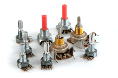
A variable resistor is a resistor whose resistance value can be freely changed.

Generally, it consists of a resistive element and a sliding element that moves on the surface of the resistive element. In other words, the resistance value is determined by the position of the sliding element.

Variable resistors are also sometimes called potentiometers.

Uses of Variable Resistors

Variable resistors are used in a variety of electronic devices. A typical example is the volume control mechanism in audio equipment. It is called a volume control.

Variable resistors are also used in game controllers, brightness adjustment mechanisms for lighting equipment, and position detection. For example, if a variable resistor is designed to move in synchronization with the windshield wipers of a car, the resistance value will change depending on the position of the windshield wipers. Using this feature, the position of the wipers can be detected by monitoring the resistance value of the variable resistor when controlling the movement of the wipers.

Because of these various applications, variable resistors are widely used not only in electronic equipment but also in marine equipment, medical equipment, construction machinery, and machine tools. Variable resistors include those whose resistance value is changed by turning a rotary shaft and those whose resistance value is changed by sliding a knob.

Principle of Variable Resistors

A variable resistor has both ends of a resistive element with a constant resistance value and three electrodes connected to a sliding element that moves on the resistive element. The resistance value between the electrodes on one side of the resistive element and the electrodes of the sliding element varies as the sliding element moves. When a voltage is applied between both terminals of the variable resistor’s resistive element, the voltage divided by the voltage is obtained from the terminals of the sliding element.

That is, when a signal voltage is applied to both ends of the resistive element, the signal voltage between one of the reference terminals and the sliding element terminal is determined by the position of the sliding element. Therefore, the level of the signal voltage can be controlled freely by moving the slider.

By applying a constant voltage to both ends of the resistive element and measuring the voltage between the reference terminal on one side and the sliding element terminal, a voltage corresponding to the position of the sliding element can be obtained. From this voltage, the position of the sliding element sliding element can be obtained, so it can be used as a displacement sensor.

Types of Variable Resistors

1. Classification by Rotary Shaft Movement

Linear Type
The linear type is a type with a sliding knob. In mutation sensor applications, it is used to detect a position on a straight line.

Rotation Type
The rotary type rotates a rotary shaft. In mutation sensor applications, it is used to detect the angle of rotation.

Multi Revolution Type
In order to change the resistance value with high accuracy, there is also a variable resistor called a multi-turn type. This type uses gears to decelerate the movement of the rotating shaft to enable subtle resistance value settings.

2. Classification by Resistance Value Change Characteristics

The resistance value of a variable resistor indicates the resistance value between the terminals at both ends of the resistive element, and generally, resistors in the range of 100Ω to 1MΩ are often used. In the rotary type variable resistors, there are three types of resistance value change with the rotation angle of the sliding element: Type B, which is a straight line; Type A, which is a logarithmic curve; and Type C, which is an inverse logarithmic curve.

Variable Resistors With A Curve Characteristics
Variable resistors are mainly used for volume control of audio equipment. Since human hearing is not proportional to the loudness of electrical signals, but to their logarithm. The A-curve characteristic is perceived as a linear change in volume by the auditory sense.

Variable Resistors With B Curve Characteristics
Variable resistors with B curve characteristics are used for adjusting electronic circuits, mutation sensors, etc.

Variable Resistors With C Curve Characteristics
This curve has the opposite characteristics of the A curve and is limited to special applications. Examples of use include adjustment of audio sound quality and effectors.

Other Information on Variable Resistors

Digital Variable Resistors

Digital variable resistors are electronic components whose resistance value can be varied by a controller, such as a PC, etc. A set of resistors and switch elements configured inside an IC can be switched by a control signal from the controller to set a desired resistance value.

Since there are no sliding elements, there is no abrasion, and a highly accurate resistance value can be obtained stably. There is also no noise generated by the sliding element. In addition, they generally have a long service life and high performance.

カテゴリー
category_usa

Image inspection software

What Is an Image Inspection Software?

Image inspection software

Visual checks usually perform visual inspections of products and materials by workers.

Compared to normal products and components, visual inspection checks for differences in shape and color, scratches and dents, and foreign matter.

In addition to skill and experience, sustained concentration is essential for this work. Lack of attention can lead to oversights, which can lead to defective products being shipped, which can lead to complaints from users.

To avoid such a situation, image inspection software uses image recognition and comparison technology to store everyday products and components in computer memory and use them as a reference to automatically check the inspected items and sort them into good and defective ones.

Uses of Image Inspection Software

Image inspection software is used in a wide variety of applications.

It is used to check for scratches and stains on the surface of metal, wood grain, and resin products, as well as the external shape and stains of food products and foreign objects.

It is also used to check for misalignments, chips, or stains in the printing of products.

Image inspection software is also available to check for chipped contact lenses, scratches on the surface of CDs/DVDs, the state of mounting of parts on printed circuit boards, soldering defects, and the presence of foreign matter or scratches on semiconductors.

Principles of Image Inspection Software

The basic structure of image inspection software is as follows:

A camera is used to capture images of good products to be compared. Features are extracted from the captured image data and stored on a computer.

Next, the image data of the inspected object is captured, and the features are extracted similarly. The similarity between the two data sets determines whether the product is good or defective.

In addition to the basic image inspection software described above, recently released systems can make more accurate judgments by incorporating AI functions.

In this case, however, many images of good products are captured, and the features of the images are extracted from them. This incorporates into the system as reference image data for testing.

The system then judges good or bad on several tested items. The system learns whether the judgment results are valid, the feature extraction data is modified, and the test is repeated several times to increase the detection rate of defective products.

カテゴリー
category_usa

Bending Machinery

What Is Bending Machinery?

Bending Machinery

Bending machinery is a processing machine used to bend thin sheet metal materials.

Bending machinery goes by a variety of names, including brake presses, benders, and bending machines. The mechanism of this machine itself is simple. Similar to a press machine, the punch die (upper die) and die block (lower die) are moved up and down to apply pressure and bend the metal sheet.

By applying vertical pressure and preparing dies that match the hardness, thickness, and bending angle of the material, it is possible to bend the material to the desired angle.

Uses of Bending Machinery

Bending machinery is used to produce shapes that are difficult to cut or to cut costs. A wide variety of products are produced using bending machinery, ranging from home appliances to automobile parts, industrial products, and parts for building materials such as aluminum sashes.

Products using these machines are made from thin metal materials, which are lightweight and can be produced in large quantities. In most cases, bending machinery is used to bend thin metal materials.

Principle of Bending Machinery

As mentioned above, the bending machinery itself is simple. Similar to a press, the punch die (upper die) and die block (lower die) are moved up and down to apply pressure and bend the metal sheet. Currently, the hydraulic press brake is the most major processing machine.

In this machine, the hydraulic cylinder will serve as the power structure for the vertical movement. The load and processing speed can be controlled because the crank part does not protrude too much.

The disadvantage of bending is that bending accuracy may vary due to springback caused by plastic deformation, which is a characteristic of bending metal under pressure. Spring back refers to the phenomenon of metal returning to its original shape.

Other Information on Bending Machinery

Types of Bending Machines

When using bending machinery, it is necessary to understand the types of bending that are possible. There are various types of upper and lower dies, and complex bending processes can be realized by combining parts.

The bending methods mainly used are as follows:

1. V-Bending
V-bending is a processing method that literally uses a V-shaped punch to push and bend a metal sheet. The die is simple and used for various bending processes. V-bending is classified into the following three types according to the degree of punching pressure.

  • Bottoming Bend (Bottoming Bend)
    A 90-degree bend in which the bend is pushed all the way to the bottom of the punch.
  • Partial Bending (Free Bending)
    A method of adjusting the bending angle by stopping the V-bend in the middle of the punch.
  • Coining Bend (Pressure Bend)
    A method of applying more pressure after the punch is pressed to the bottom like a bottoming bend.

Generally, in V-bending, the more pressure is applied, the smaller the bending R and springback becomes. Therefore, the coining bend can perform the most precise processing, but it requires 5 times more pressure than the bottoming bend to apply pressure, and the die is subject to severe wear.

2. L-Shape Bending
L-shape bending is a processing method to bend a metal sheet at right angles by clamping the top and bottom of the sheet and pressing the protruding part with a punch. It is also called “hold down bending.” Since the sheet is bent while being held down, the forming process is more stable than V bending. It is also possible to bend long metal sheets that cannot be bent with V-bending.

3. U-Bending
U-bending is a processing method in which pressure is applied to a metal sheet while holding it with a punch from above and a movable pad from below, and the sheet is bent into a U-shape in line with the fixed platforms on either side during processing. Since there is little variation in bending accuracy and forming is possible with a single bending, man-hours required for bending can be reduced.

However, a dedicated die is required for each shape when forming, and the startup cost is high.

4. Z-Bending
Z-bending is a processing method to bend a metal sheet into a Z-shape. z-bending is a method to bend a metal sheet into a Z-shape by either performing L-bending twice as described above (once bent, the reverse side of the sheet is reversed and bent again) or by bottom-bending with a special punch during L-bending and pushing the sheet once.

Forming once is more accurate than L-bending twice, but the cost is naturally higher.

カテゴリー
category_usa

Ball Bearings

What Is a Plain Bearing?

A plain bearing is a bearing that directly supports the rotation of a shaft or the linear motion of moving parts by the sliding surfaces of the bearing. Since the rotating shaft or moving parts are in direct contact with the sliding surfaces of plain bearings, frictional forces are high, and frictional heat is generated. For this reason, the contact surfaces are lubricated with oil, metal impregnated with a lubricant on the plain bearing sliding surfaces, or a resin material with high lubricating properties.

Plain bearings that do not use lubricants are called Dry Bearings. Plain bearings are inexpensive, easy to use, and flexible in terms of material and size, and they are used for different purposes and in different operating environments.

Plain bearings are classified into the following three types:

  • Plain bearing
  • Sliding bearing
  • Slide bearing

Uses of Plain Bearings

Plain bearings have the following characteristics, especially when compared to rolling bearings:

  • Simple structure and shape
  • Compact in size
  • High-speed performance (high-speed rotation)
  • Not suitable for low-speed performance (low-speed rotation)
  • Relatively large allowable load
  • Quiet noise and low vibration
  • Long life

Types of Plain Bearings

Plain bearings used in general industrial applications are classified according to load type, material, and shape/structure.

ISO 4378-1 classifies them as follows:

1. Load Type

Load types are divided into four types: hydrodynamic bearings, hydrostatic bearings, journal bearings, and thrust bearings.

Dynamic and Hydrostatic Bearings
In a hydrodynamic bearing, the dynamic pressure generated by the rotation of the shaft forms an oil film between the shaft and the bearing surface to support the shaft. There are several ways to generate hydrodynamic pressure, such as wedging the gap or applying sliding surface construction to the sliding surfaces. In general, plain bearing passive is often used to indicate a hydrodynamic bearing.

Hydrostatic bearings support a shaft by supplying oil (lubricating oil) or compressed air to the bearing from equipment or facilities outside the bearing and filling the pocket between the shaft and bearing.

Journal Bearings and Thrust Bearings
Journal bearings are used when loads are applied in the centerline direction (radial direction) of the shaft. Thrust bearings are used when the load is applied to the bearing in the direction perpendicular to the shaft centerline (thrust direction).

2. Material

There are two types of materials: resinous and metallic.

Resin Type
Examples of resin-based materials are shown below:

  • Tetrafluoroethylene resin (PTFE)
  • Polyacetal resin (POM)
  • Polyetheretherketone resin (PEEK)
  • Polyphenylene sulfard resin (PPS)
  • Polyester elastomer resin
  • Polyamide resin (PA)

Plain bearings are lubricated with oil or graphite to improve lubricity and are used without lubrication in most cases. They may also be used in combination with metals to improve mechanical strength.

Metallic Materials
Examples of metallic materials are shown below:

  • Lead copper castings (JIS H5120 CAC601, CAC603, CAC606)
  • Phosphor bronze casting (JIS H5120 CAC502A)
  • White metals (JIS H5401 WJ1 to WJ10)
  • Aluminum alloys (JIS AJ2, SAE770, 780, 781)

White metals, copper alloys, and aluminum alloys are the most common metallic materials used with lubricants. White metals are often used for static loads and ship engines, while copper-based alloys are often used for bushings due to their superior wear resistance.

Aluminum alloys on the other hand are used in a wide range of applications, including engine applications and bushings. Oilless plain bearings are lubricated by adding lubricant, coating the surface, or embedding a solid lubricant material. Oilless plain bearings are called Oilless Bearings.

Shape and Structure
Types by shape and structure are divided into cylindrical, cylindrical with flange, disk (thrust bearing), and spherical (spherical thrust bearing).

Principles of Plain Bearing

Plain bearings are supported by the sliding surfaces of the rotating shaft or moving parts and the sliding surfaces of the plain bearing making contact with each other. Therefore, it is important to deal with the friction that occurs between the surfaces (sliding surfaces).

In general, plain bearings use lubricating oil, lubricant, or air on the sliding surfaces to reduce frictional resistance. Therefore, the state of lubrication of the sliding surfaces is very important. The lubrication condition is classified into the following three types, which are shown in Figure 3 Stripek curve:

1. Boundary Lubrication

The sliding surfaces are almost solidly lubricated due to high friction without sufficient lubrication film formation, which may lead to seizure and sticking.

2. Mixed Lubrication

Sliding surfaces have almost the same surface roughness and lubricating film thickness and are in a mixed state of fluid and solid contact, which is not completely satisfactory.

3. Fluid Lubrication

Sliding surfaces are well lubricated with a sufficient lubricating film and are not in direct contact with each other, with no mutual wear.

Plain bearings can be lubricated by forced lubrication, oil bath, splash lubrication, or drop lubrication, depending on the operating conditions of the bearing. Forced lubrication is a method in which lubricating oil is pumped to the bearing lubrication area to ensure a constant supply of lubricating oil. Oil bath and splash lubrication do not require lubrication equipment and can be made into a simple structure. Drip lubrication is not suitable for high-load operation because the amount of lubricating oil is small.

For forced lubrication, there are two methods: lubricating the housing side and lubricating the shaft side. It is also possible to improve the cooling effect by installing oil grooves on the housing and shaft. However, the lubricating film may become discontinuous, resulting in a reduction in bearing load capacity, so care must be taken in the design of the oil groove.

In environments where lubricating oil cannot be used (e.g., high temperatures), solid lubricants may be used. Solid lubricants include graphite and PTFE. Plain Bearings can have a long service life if hydraulic pressure, oil film, etc. are accurately controlled.

Other Information on Plain Bearing

Plain Bearing Standards

JIS and ISO standards for plain bearings are listed below.

The specifications of rolling bearings are specified in standards, so all manufacturers have the same specifications for fitting tolerances, manufacturing tolerances, clearance tolerances, and so on, depending on the bearing type. Therefore, they are interchangeable and can be used as general-purpose parts.

Plain bearings, on the other hand, do not have a common international standard. Therefore, they are not interchangeable and cannot be used as general-purpose parts. Consequently, a decision must be made based on the application, operating environment, and design specifications.

カテゴリー
category_usa

Mold Temperature Controllers

What Is a Mold Temperature Controller?

A mold temperature controller is a device used to maintain the temperature of molds used in injection molding, extrusion molding, and other plastic product molding processes at a constant temperature.

Mold temperature is affected not only by seasonal variations but also by temperature differences between morning and evening. Mold temperature controllers must maintain a constant mold temperature to stabilize the quality of molded products.

This is similar to a mold cooler (chiller). Mold chillers specialize in circulating chilled water to lower mold temperature. On the other hand, mold temperature controllers use oil and water as the circulating medium, making it possible to maintain a constant mold temperature not only at low temperatures but also at temperatures of 100°C or higher.

Uses of Mold Temperature Controllers

Mold temperatures that are too high or too low can significantly affect the quality of molded products. Low mold temperatures cause flow marks, cracks, luster defects, and other problems. On the other hand, too high a mold temperature can cause warpage, dimensional defects, sink marks, etc.

Mold temperature controllers maintain a constant mold temperature and prevent these defects.

Water-based mold temperature controllers can control temperatures up to about 90°C. Oil-based mold temperature controllers can control temperatures higher than that. Oil-based mold temperature controllers are used to control temperatures above that level.

For example, polyvinyl chloride (PVC), polycarbonate (PC), polypropylene (PP), and polystyrene (PS) use water-based mold temperature controllers.

On the other hand, PET (polyethylene terephthalate) and PPS (polyphenylene sulfide), which require control at high temperatures, use oil-based mold temperature controllers.

Principles of Mold Temperature Controllers

  • Principle of Temperature Control: Mold temperature controllers keep the mold’s temperature constant through heat exchange by circulating a temperature-controlled medium, such as water or oil, through piping that passes into the mold.

Heat exchange refers to transferring heat energy from the hotter mold to the cooler water or oil medium. The temperature difference between the temperature of the medium entering the mold and the temperature of the medium leaving the mold is one indicator of the performance efficiency of mold temperature controllers.

Water mold temperature controllers use a direct cooling method to control the temperature by controlling the circulation and discharge of water through pipes that pass into the mold. On the other hand, an oil-based mold temperature controller uses an indirect cooling method in which an oil medium circulates in the mold piping, and the temperature of the medium is controlled by the cooling water.

  • Usefulness of Mold Temperature Controllers: In injection molding, cooling the hot resin stabilizes the shape of the molded product and allows it to be removed from the mold. Although mold release is possible without a mold temperature controller by releasing heat to the outside air, using a mold temperature controller stabilizes the quality of the molded product and promotes rapid mold release, thereby improving production efficiency.


カテゴリー
category_usa

Optical Switches

What Is an Optical Switch?

Optical switches, also known as optical line switching devices, are devices used in optical communications to branch or alter the destination of a specific signal without converting it from an optical signal to an electrical signal.

Since there is no need to convert optical signals into electrical signals, switching can occur while maintaining the high-speed characteristics of optical communications.

Optical switches can be broadly classified into three types based on the switching method:

1. The mechanical method involves switching the optical path by moving an input/output element or optical element mounted on an electrical actuator.

2. The MEMS method switches by controlling the position of a minute optical element using a weak force such as static electricity. It switches by reflecting light from two mirrors. MEMS switches can be integrated into a small size and operate at high speeds, making them suitable for multi-channel switching. Although the device must be constantly energized, it is possible to reduce power consumption because the power required to operate each element is also small.

3. The bending method switches by placing heaters on both sides of the optical waveguide on a substrate. This heats one side of the heater to create a temperature difference between the left and right sides of the waveguide. The optical waveguide method changes the refractive index in the waveguide by creating a temperature difference between the left and right sides, thereby altering the light propagation path.

Uses of Optical Switches

Optical switches are utilized in devices that control optical paths and manage light in optical communications, which are now essential for high-speed communications.

When optical communications are converted to electrical signals before switching, the time required from conversion to switching becomes a bottleneck. Optical switches were developed to address this issue by performing switching using light.

Optical switches continuously provide a stable optical access environment by switching to alternative paths when one optical path becomes unavailable due to device failure or other reasons.

Principles of Optical Switches

The mechanical method has a straightforward structure, and switching is achieved by sliding optical elements such as prisms. The control system is user-friendly, and losses are minimal.

The MEMS method is an optical switch that uses micro-mirrors, which can be fabricated with advancements in microfabrication technology. It switches by reflecting light from two mirrors. MEMS switches can be integrated into a small size and operate at high speeds, making them suitable for multi-channel switching. Although the device must be constantly energized, it is possible to reduce power consumption because the power required to operate each element is also small.

The optical waveguide type is realized using lightwave circuit technology, which creates an optical waveguide on a flat surface. It changes the optical path by altering the refractive index or using external inputs such as heat, light, or electricity. Although it incurs some loss, it can stack planar surfaces and is characterized by its compact size and ease of integration.

カテゴリー
category_usa

Tool Grinding Machinery

What Is Tool Grinding Machinery?

Tool grinding machinery is used to regrind cutting tools that have lost their sharpness after a certain amount of cutting.

Tool grinding machinery is also called a grinder. In this case, cutting tools include drills, end mills, milling cutters, and hob cutters.

There are various types of grinders depending on the type of tool grinding machinery, each of which is used in a specialized machine-like manner. Specifically, they include drill grinders, cutter grinders, and hob grinders. There are also universal tool grinding machines that can grind many types of tools. By equipping them with a variety of auxiliary equipment, they can be used for a wide range of tools.

Uses of Tool Grinding Machinery

Tool grinding machinery is used for regrinding cutting tools. Tools to be ground with tool grinding machinery are used to machine metal and are called cutting tools.

Universal tool grinding machinery, which allows for general-purpose use, may not be able to regrind end mills and other tools with complex shapes. In addition, they generally require manual grinding, which requires skill.

On the other hand, with the advent of CNC tool grinding machinery, which now controls multiple axes through numerical control, along with technological innovation, it is possible to perform automatic grinding of tools with complex shapes. Appropriate search conditions and grinding wheel selection ensure stable grinding. By freely rotating the grinding wheel axis, a variety of tools can be ground in a single clamping for a high quality finish.

Principle of Tool Grinding Machinery

Tool grinding machinery is used to grind the surface of a tool that has lost its sharpness by placing the tool gradually against a grinding wheel rotating at high speed. These processes make it possible to regain sharpness.

Tools with common shapes, such as end mills, milling cutters, reamers, and taps, can be ground quickly with universal tool grinding machinery because they do not require complex program setups and can be ground manually. However, for grinding a large number of tools with complex geometries in a stable manner, CNC tool grinding machinery has the advantage.

Universal tool grinding machinery requires skill because two or three axes must be operated manually and simultaneously. There are also simplified NC tool grinding machinery that simplifies the grinding process by using NC control for only one axis. When only the main axis is NC-controlled, grinding can be performed without the need for skilled operators, such as the spiral shape of the clearance and rake surfaces of the outer circumference of an end mill or the spiral shape of the rake and clearance surfaces of a ball end mill R.

Types of Tool Grinding Machinery

The following three types of tool grinding machinery are typical types.

1. Universal Tool Grinding Machinery

Universal tool grinding machinery is used for grinding common drills and end mills. Universal tool grinding machinery has a number of adjustment axes that allow the structure and shape of the tool to be ground to be adjusted to various shapes, diameters, lengths, and cutting edge conditions. However, knowledge of the tool to be searched for is required. In addition, skill is required to operate the numerous adjustment axes properly.

2. CNC Tool Grinding Machinery

Today, CNC tool grinding machinery, which has a metal method that can move multiple axes simultaneously or in conjunction with each other, is the most commonly used for machining common tools. Some of these newer CNC tool grinding machinery have functions to measure the shape of the ground tool and to adjust the machining allowance by detecting deformation of the grinding wheel due to machining heat.

3. Special-Purpose Grinding Machines

Dedicated grinding machines are available for hobs and pinion cutters used for machining gears with special shapes, and for broaches used for machining key grooves, spline grooves, etc.

Other Information on Tool Grinding Machinery

1. The Difference Between Grinding and Polishing or Cutting Processes

Grinding and polishing processes are the same in that they are performed to regenerate the sharpness of a tool, but the methods of regeneration are different. In grinding, abrasive grains are used to shave the tool blade and change the shape itself, while in polishing, abrasive grains are used to apply pressure to the tool blade in order to polish the surface smooth.

Cutting is often performed not with abrasive grains, but with reamers, end mills, and other tools with the purpose of cutting away the shape of the workpiece, which is then fine-tuned by grinding or polishing.

2. Grinding Wheels for Tool Grinding Machinery

Cutting tools are made of materials that are harder than ordinary steel, such as high-speed tool steel and cemented carbide. In addition, heat treatment and surface treatment are applied to increase the hardness of the material.

On the other hand, since the accuracy of cutting tool edge dimensions greatly affects the accuracy of finished dimensions during machining, grinding wheels coated with diamond or CBN (Carbon Boron Nitride) are used to grind high-precision, high-hardness work materials. During the grinding process, the heat generated during machining affects the dimensions of the grinding wheel or diamond wheel and the tool being ground, which in turn greatly affects the finished dimensions of the tool.

Although some recent CNC tool grinding machinery uses those heats to compensate for the dimensions, it is essential to use a grinding fluid that controls the temperature rise and controls the temperature because it affects the hardness and material composition of the tool being ground. The selection of the grinding fluid, as well as the tool grinding machinery, is important.

カテゴリー
category_usa

Hardness Testing Instruments

What Is a Hardness Testing Instrument?

Hardness Testing Instruments

Hardness testing instruments evaluate the hardness of various materials and products.

Depending on their basic principles, hardness testing methods can be broadly classified into indentation testing and dynamic testing. The indentation test is performed by pressing a hard indenter into the surface of a test specimen and measuring the size of the surface area or depth of the indentation. The smaller the indentation area and the shallower the indentation depth, the harder the material is evaluated.

In the dynamic test method, a hammer is dropped from a certain height, and its rebound height is measured. This test method is called the Shore hardness test and utilizes the property that the harder the specimen is, the higher it will bounce back.

Various hardness testing instruments are used to perform the above test methods, depending on the indenter, the load applied to the indenter, and how the indentation is measured. When evaluating hardness, it is essential to select the appropriate testing method and instrument based on the test specimen’s size, shape, and purpose, as well as on the agreement between the recipient and the testing party.

Uses of Hardness Testing Instruments

  1. Test Method to Measure Surface Area of Indentation

Vickers hardness test and Brinell hardness test are used to measure the surface area of indentation.

Vickers Testing Instrument

Vickers hardness testing instruments are used to test various materials, including metallic materials. It is characterized by a small test load and evaluates hardness in a narrow range. It is also used to assess the hardened layer depth of various surface treatments, such as carburizing, induction hardening, and nitriding layers, as well as the hardness distribution of welds.

Brinell Hardness Testing Instrument

The Brinell hardness testing instrument tests castings, forgings, and other metallic materials with rough surfaces and heterogeneous grain structures. It is characterized by a large test load and large indentation, allowing for average hardness evaluation over a relatively wide range.

  1. Indent Depth Test Method

The Rockwell hardness test is a test method to measure indentation depth. The Rockwell hardness testing instrument is mainly used for hardened metal materials. When evaluating the hardness of the hardened layer in hardened metal materials, the appropriate test conditions (set as a scale) must be selected according to the hardness and depth of the hardened layer.

Shore hardness testing, a dynamic test method, is used to test the hardness of large parts and rolling rolls and is a common test method used in the field within machine shops. The advantages of the Shore hardness testing instrument are that it can be used for product inspection because the indentation is less noticeable, and the instrument is small and portable.

Principles of Hardness Testing Instruments

The principles of hardness testing instruments differ depending on the type.

  1. Vickers Hardness Testing Instrument

In the Vickers hardness testing instrument, a diamond indenter with a 136° square face angle is pressed into a test specimen under a test load. The diagonal length of the square indentation created by this load is measured with a metallographic microscope attached to the tester.

JIS specifies test loads from 10gf to 100kgf. The test performed at one kgf or less is called the micro-Vickers hardness test. The testing instrument is the same for both Vickers and Micro-Vickers testing instruments. Both tests can be performed by changing the test load. Changing the test load does not change the hardness value as long as there is no irregularity in the material.

For the Vickers hardness test, the specimen should be no larger than the palm size. The surface to be tested also needs to be mirror polished, so it is almost always necessary to cut out the part of the specimen whose hardness is to be determined.

  1. Brinell Hardness Testing Instrument

The Brinell Hardness testing instrument uses a ball indenter, steel, or cemented carbide ball 10 mm in diameter. A test load of 3,000 kgf is often used. The load is calculated by dividing the load applied to a spherical indentation in the test surface by the surface area of the permanent indentation.

  1. Rockwell Hardness Testing Instrument

The Rockwell hardness testing instrument applies load in three stages. First, a reference load is used, then a higher test load is applied, and then the load is returned to the reference load. The hardness evaluation is based on the difference in indentation depths between the two reference loads applied before and after the test.

In the Rockwell hardness test, the scale is determined by the combination of several test loads and indenter types. For example, if a diamond cone with a tip radius of 0.2 mm and a tip angle of 120° is used and the primary load is ten kgf, the A scale is used if the test load is 60 kgf, the D scale if 100 kgf, and the C scale if 150 kgf.

A test using a 1/16″ (1.5875mm) steel ball with a basic load of 10kgf and a test load of 100kgf falls under the B scale. Tests conducted with a basic load of 3 kgf and test loads of 15, 30, and 45 kgf are called Rockwell superficial hardness tests. It is used especially for hardness testing of thin steel plates.

In today’s Rockwell hardness testing instruments, the indenter is interchangeable and can be set to different base and test loads. The advantage is that loadings and depth measurements are performed automatically.

  1. Shore Hardness Testing Instrument

In the Shore hardness test, a diamond hammer of a specific shape and mass is dropped on a test specimen from a certain height, and the bounce height is measured. Unlike other testing instruments, the Shore hardness testing instrument is very small and uses no electricity.

Other Information About Hardness Testing Instruments

Calibration of Hardness Testing Instruments

Hardness testing instruments need to be calibrated periodically to ensure that they are performing correctly. The testing machine manufacturer usually services this.

Also, in daily operations, checking the accuracy using test specimens is essential. A standard test specimen with guaranteed hardness is prepared, and before the actual test is conducted, it is checked to ensure the correct results can be obtained with the standard test specimen. This preliminary check can also help you notice mistakes in test load or indenter selection.

カテゴリー
category_usa

Adhesion Testers

What Is an Adhesion Tester?

An adhesion tester is a testing device widely and generally used to evaluate the hardness of surfaces of metals, resins, rubber products, and other materials.

Devices to evaluate the hardness of metals are often called “hardness testers,” while those to evaluate the hardness of relatively soft materials such as resin and rubber are often called “adhesion testers,” but there is no clear definition in practice. There are also adhesion testers used to measure the mineral content of water.

The correct definition of hardness is a numerical value based on the results of a test to evaluate hardness, such as the change in a product when something called an indenter is pressed into the part to be measured. There are various methods of testing to indicate hardness. There are many types of materials to be measured, including metals and resins, and it is important to select the method of measuring hardness according to the application.

Uses of Adhesion Testers

Typical applications of adhesion testers are as follows:

1. Rockwell Hardness

A type of indentation hardness test, in which an indenter, such as a diamond or hard ball, is applied to the material to be measured under a defined load to create an indentation. The depth of the indentation is used to measure the hardness.

First, the indenter is subjected to a standard push load to determine the origin of the depth. Then, an additional load is applied to the indenter and held for a certain period until it reaches the specified test load, after which the load is returned to the reference load. The hardness is evaluated based on the difference between the depth at which the reference load is first applied and the depth at which the load is returned to the reference load.

This test is mainly used to evaluate the hardness of heat-treated steel materials. It is widely used together with the Vickers hardness test, which is a hardness test for metals. However, since the test load is higher than that of the Vickers hardness test, a specimen that can withstand the test load is required.

2. Vickers Hardness

This is a type of indentation hardness test in which a diamond is pressed against the material to be measured as an indenter to make an indentation, and the hardness is measured from the load applied and the surface area of the indentation. The size of the indentation is measured with a metallographic microscope.

This test is mainly used to evaluate the hardness of metals, but it can be used to evaluate a very narrow range of hardness. It is also used to evaluate the depth of hardening in heat-treated metals. It is called effective hardened layer depth.

3. Shore Hardness

Shore hardness is a type of rebound hardness, which is measured by dropping an indenter with a diamond attached to the tip of a copper rod onto the object to be measured and measuring the height of the indenter’s rebound after striking the object. In the rebound height test, the indenter is dropped from a specific height and measured from the magnitude of rebound (height of rebound) after hitting the object.

Therefore, no power supply is required. On-site testing of large buildings, etc., is possible.

Principle of Adhesion Testers

There are two main methods for evaluating hardness: indentation hardness and rebound hardness.

1. Indentation Hardness

A hard material called an indenter, such as diamond, is pressed against the material to be measured, and the hardness is determined by the depth of the indentation. Brinell hardness, Rockwell hardness, Vickers hardness, etc. are used to evaluate the hardness of metals.

2. Rebound Hardness

The hardness is measured by the amount of rebound of the indenter after it strikes the material to be measured. Shore hardness is one of the main tests.

Other Information on Adhesion Testers

1. Food Adhesion Tester

Measuring instruments for measuring the hardness of food products are called rheometers or rheotesters. Foods to be measured by rheometers are much softer than the so-called hardness tester categories in this volume and cannot be measured by the above mentioned adhesion testers.

The measurement unit of the rheometer, like other hardness units, is not specified, so the unit of measurement is either the same as that of the load cell or force tester used in the measurement, or, if a compression plate is used, it is indicated as per surface accuracy of the compression plate (N/㎟), etc. However, as with other hardness values, data correlation is weak, so evaluation is based on relative comparisons between data measured with the same measuring instrument.

2. Water Adhesion Tester

Water hardness is what is referred to as hard water or soft water. Water hardness is the sum of 2.5 times the amount of calcium (Cax2.5) and 4 times the amount of magnesium (mgx4) contained in water, and is measured using a chemical reaction measuring instrument and reagents. The unit is expressed in mg/L (U.S. hardness), with higher values indicating hard water and lower values soft water.