カテゴリー
category_usa

Lumina Automatic Spray Guns

What Is a Lumina Automatic Spray Gun?

A Lumina automatic spray gun is a coating equipment that can spray liquid into atomized form. There is an extensive lineup of products, from the characteristics of the main unit to the ability to adjust the amount of liquid and the pattern of application.

The characteristics of the main body include circulation specifications suitable for liquids that easily separate, and stainless steel construction suitable for liquids with corrosive properties, to meet a wide variety of needs.

Spray application is made possible by liquid nozzles consisting of five different types to allow a variety of patterns, which can also be selected according to the particle size of the spray and the type of liquid used .

Uses of Lumina Automatic Spray Guns

Lumina automatic spray guns are used for dispensing and painting because they can output liquids in atomized form and can also adjust the particle size of the spray that is injected.

In particular, it is suitable for oil spraying, so it is used for the application of various oils, such as release agents, oils for food processing and presses, coating with various paints, such as UV paints and photocatalytic paints, and humidification. It is also used for applying adhesives such as bonds and for the application of high-viscosity liquids.

Principle of Lumina Automatic Spray Guns

Liquids can be atomized by a spray gun which is explained below.

This is achieved by mixing the liquid with compressed air, which turns the liquid into fine particles. The atomization of the liquid into fine particles allows it to be spread evenly and thinly.
This is followed by the structural principle of an automatic spray gun.
Another structural feature of automatic spray guns is that they are turned on and off by automatic control.
While manual spray guns are controlled by pulling a trigger, automatic spray guns are controlled by compressed air.

When compressed air enters the automatic spray gun, the needle is pulled, the liquid passage is opened, and the liquid and compressed air mix to create finer particles of liquid, which are then ejected from the spray port. structure allows compressed air to simultaneously change the state of the liquid and automatically control it.

カテゴリー
category_usa

Laser Mirrors

What Is a Laser Mirror?

Laser mirrors are specialized mirrors designed to reflect laser light.

They are characterized by high reflectivity and thermal tolerance and are used to maximize the energy of the laser beam. They serve various purposes in laser devices and optics, with their primary application being the focusing and propagation of laser light in the form of a beam.

The laser beam emitted from a laser device is directed by a laser mirror, allowing precise control of the beam’s direction. Laser mirrors are also used as reflectors for lasers. Ordinary mirrors can lead to thermal damage since laser beams are produced at specific wavelengths and power levels.

Laser mirrors are often manufactured with specialized coatings and materials that provide high reflectivity for specific wavelengths and power levels while minimizing thermal damage.

Uses of Laser Mirrors

Laser mirrors find applications in various fields and industries. Below are some examples of their uses:
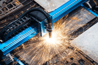
1. Manufacturing

Laser mirrors play a vital role in manufacturing processes like laser cutting and laser marking. Their high reflectivity and heat tolerance enable precise laser beam guidance.

In laser cutting, laser mirrors focus the laser beam on the material to be cut. In laser marking equipment, a focused laser beam is used for marking or engraving. In laser welding, laser mirrors control the welding process by focusing the laser beam on the material.

2. Medical Applications

Laser mirrors are widely used in the medical field, particularly in laser surgery. They guide the laser beam into a patient’s body.

In skin treatments, mirrors are used to precisely direct the laser beam for treating skin lesions and unwanted tissue. In ophthalmic surgery, mirrors guide the laser beam into the eye for surgery or treatment. Laser mirrors are crucial for the effective and safe use of laser light due to their high reflectivity and heat tolerance.

3. Telecommunications

Laser mirrors are essential components in the field of fiber optics and optical communications. Optical fibers are used for high-speed transmission of information, and laser mirrors reflect and guide optical signals.

Mirrors are used at the ends and junctions of optical fibers to precisely control optical signals, ensuring high-speed, high-quality communication. Optical communication networks also employ mirrors for routing and optical switching to transmit and control signals effectively.

Principle of Laser Mirrors

A laser mirror consists of a reflective layer, a substrate, and a protective coating.

1. Reflective Layer

The reflective layer’s role is to reflect the laser beam and is typically coated with a highly reflective material like metal or dielectric deposition. The thickness and material choice depend on the mirror’s characteristics and the laser mirror’s wavelength.

2. Substrate

The substrate provides support to the reflective layer, ensuring stability. Typically, rigid materials like glass or metal are used. Substrate flatness and heat resistance are crucial, and high-quality substrates are preferred to maintain laser beam quality.

3. Protective Coating

A protective coating is often applied since laser mirrors may be exposed to dirt and scratches during use. This coating protects the mirror surface and enhances wear and chemical resistance.

Types of Laser Mirrors

There are several types of laser mirrors with varying coatings, properties, and applications. Here are some typical examples:

1. Metal Coating

These mirrors are coated with materials like gold, silver, or aluminum. They are cost-effective and suitable for a broad wavelength range.

Gold transmits at wavelengths of 600 nm or less, while silver transmits at wavelengths of 400 nm or less. However, they are susceptible to surface scratches.

2. Broadband Dielectric Coating

This type of mirror features a broadband, highly reflective coating. The film doesn’t absorb light and is used for laser light sources with multiple wavelengths.

3. Dielectric Coating for Lasers

These mirrors have coatings highly reflective at specific wavelengths. They are commonly used for short-wavelength lasers and high-power lasers. Additionally, they have the advantage of not absorbing light and are hard and scratch-resistant.

カテゴリー
category_usa

Laser Punch Combo Machine

What Is Laser Punch Combo Machine?

Laser Punch Combo Machine

Laser punch combo machine utilize a high-power laser beam to cut materials like metals and acrylics with precision. These machines are highly accurate and fast, making them ideal for mass production across various industries. They are now more affordable, allowing even individuals with DIY hobbies to access them.

Uses of Laser Punch Combo Machine

Laser punch combo machine are employed in diverse sectors:

  • Metal Processing: Used in the automotive and aerospace industries for cutting steel plates, stainless steel, and other metals.
  • Sheet Metal Processing: Ideal for efficiently cutting sheet metal used in automotive parts and construction materials.
  • Plastic Processing: Employed in the manufacture of plastic parts for electronics, medical devices, and packaging products.
  • Medical Care: Increasingly used in surgeries for precise excision with minimal bleeding.

Principle of Laser Punch Combo Machine

Laser cutting and punching machines consist of a laser oscillator, light path, and focusing unit. They operate by irradiating a focused laser beam onto the material to melt and cut it, with the cut debris often blown away by air jets. The process requires careful heat management to ensure optimal cutting quality.

How to Select Laser Punch Combo Machine

Key considerations when selecting these machines include:

  • Material Specifications: Choose based on the type and thickness of the material. Different materials may require varying laser wavelengths and power.
  • Cutting Accuracy and Speed: High cutting accuracy requires precise optics and focusing capability, while working speed influences productivity.
  • Safety and Regulation: Ensure the machinery has proper safety features and complies with relevant regulations.
カテゴリー
category_usa

Logic Probes

What Is a Logic Probe?

In general, a probe is a device that detects the signal to be measured and transmits it to a measuring instrument when observing a waveform, and a logic probe is positioned as a special probe among these probes.
Logic probes are sometimes used for scopecoders, which are integrated measurement instruments, and mixed-signal oscilloscopes, which can also handle RF signals, analog and digital. Proper use of probes is important for accurate measurements.

Uses of Logic Probes

Logic probes are generally supplied with oscilloscopes as specialized probes suitable for that oscilloscope, and are used for the detection and transmission of the target signal when observing waveforms, which is why logic probes are classified as special probes.
Logic probes are available in a lineup with added features such as the presence or absence of insulation, high-speed transmission, etc., according to the application.

Principle of Logic Probes

The probe is characterized by its ability to detect signals and transmit signals while functioning as part of a measuring instrument. For this reason, the probe’s output impedance, frequency, voltage, current, amplitude, and other values ​​that the probe has may affect the measurement, requiring an understanding of the signal to be measured and the characteristics that the probe has.

Having the right probes for your oscilloscope is very important to making accurate measurements, which is why oscilloscopes come with dedicated probes.

Many failures in digital systems are due to the analog characteristics of digital waveforms, and in order to analyze the analog cause, it is necessary to observe specific pulses, which requires the functionality of a logic analyzer. To meet this need, logic probes are designed with compatible logic circuits and are capable of both synchronous and asynchronous operations.

カテゴリー
category_usa

Electrical Discharge Machining (EDM)

What Is Electrical Discharge Machining (EDM)?

A wire electric discharge machine is a machine tool that processes materials by means of the electrical discharge phenomenon in liquids, such as water or oil, which occurs when the wire that serves as the electrode is energized in the liquid.

The energized wire sparks in the liquid, and the molten metal is repeatedly cooled and dispersed by the liquid to form the external shape of the processed material. Ultra-thin brass (brass) wire with a diameter of about 0.05 to 0.3 mm is used as the wire for processing.

The wire used for processing discharges electricity and does not come into direct contact with the material to be processed.

Uses of Electrical Discharge Machining (EDM)

Electrical discharge machining (EDM) is used when extremely hard materials need to be processed precisely. Examples include the fabrication of press dies and the machining of carbide tool edges.

Electrical discharge machining (EDM) can process any material that conducts electricity. Examples include cemented carbide, titanium, stainless steel, and molybdenum. However, it should be noted that processing time varies depending on the size and material to be processed.

Principles of Electrical Discharge Machining (EDM)

Wire EDM is performed as follows after the work material is immersed in the machine’s processing fluid.

  1. The wire, which is in an insulated state, and the work material approach each other in the processing fluid.
  2. Spark discharges are initiated and pulse currents flow, which generate temperatures of thousands of degrees Celsius, melting the processed material.
  3. The high temperature generated causes a steam explosion of the processing fluid, which blows off the molten metal and removes it.
  4. Water enters the concave areas created by the removed material and cools the material.

By repeating the above process along the shape to be processed, wire EDM processing is performed. The advantages of wire EDM are that “even the hardest materials can be processed” and “precise processing is possible.” On the other hand, because of the above processing method, the processing speed is basically slow, and it is not suitable for mass production.

Another disadvantage is that it is not possible to process the bottom portion of the workpiece or to process in the horizontal direction.

Features of Electrical Discharge Machining (EDM)

Electrical Discharge Machining (EDM) has the following three main features:

1. Various Shapes Can Be Machined With High Precision

Electrical discharge machining (EDM) machines can process even complex shapes with high precision because they process with ultra-fine wires according to a pre-registered program. An example of utilizing this feature is the machining of minute gears.

Due to the characteristics of gears as parts, machining accuracy easily leads to differences in gear performance, such as “the shape of the shaft hole must be close to a perfect circle” and “the tooth tip shape must be correct.” Fine gears may require machining with a dimensional accuracy of φ0.05 mm or less. However, this accuracy is difficult to achieve with ordinary machining methods, such as cutting.

In contrast, wire EDM uses ultra-fine wire, which enables machining of the gear center hole and tooth tip shape as per the dimensions. 

2. Machining of Difficult-To-Cut Materials Is Possible

Because the electric energy of the discharge cuts the processed material, it is possible to process any conductive material, no matter how hard it is. An example of utilizing this feature is ultra-precision press die machining. Press dies use a metal material with high hardness as the die material because of the extremely high pressure applied during the pressing process.

Since it is difficult to process complex shapes with high precision using ordinary processing methods, such as cutting, cutting by wire EDM is used. 

3. No External Force Is Applied to the Processed Material.

Wire EDM is a non-contact machining process, so no load is applied to the material being machined. Therefore, no burrs are produced on the cut surface and chamfering is not required compared to the cutting process.

Electrical Discharge Machining (EDM) Machine Structure

The structure of electrical discharge machining (EDM) consists of the following:

  • Wire
  • A drive unit that feeds the wire
  • A table on which the processing materials are placed
  • A processing tank for storing processing fluid
  • Deionizer
  • Power supply unit
  • NC device

There are two types of circuits for discharging: capacitor discharge circuits and transistor discharge circuits. Compared to capacitor discharge circuits, transistor discharge circuits can control the electrical energy during discharge.

Increasing the output increases the processing speed, but the surface roughness of the cut portion becomes rougher. Conversely, a smaller output slows down the processing speed, but the surface roughness becomes finer. 

カテゴリー
category_usa

Compression Testers

What Is a Compression Tester?

Compression Testers

Compression testers check a member’s behavior by applying a force to it in the direction of compression or measuring its physical properties by causing it to fail in compression.

Mainly, it can continuously measure the force and displacement generated during the test over a predetermined period.

Some testers can perform tests in the tensile direction by changing the direction of the load cell (the sensor that measures force).

A wide range of testing machines is available from various companies, from compact tabletop testing machines (measuring a few N) to testing machines used for crushing concrete and metal (measuring several thousand kN).

Uses of Compression Testers

Compression testers are used to check the physical properties of materials under compression in basic research at laboratories and material manufacturers and for destructive testing under compression at industrial manufacturers.

The testing machines are often available at industrial research institutes and industrial testing facilities. They can be used at a relatively low cost (several thousand yen per hour) compared to the cost of purchasing a testing machine by applying for their use.

In many cases, an industrial testing laboratory can handle the testing equipment with advanced arrangements. Such as, when the workpiece is simple and portable, no special jigs or tools are needed for workpiece installation, the testing conditions (head speed, assumed stroke) have already been determined, and the number of workpieces is fixed.

Principles of Compression Testers

The compression tester consists of a base on which a workpiece is installed, a movable part to which a load cell is attached at the top, and a PC or touch panel to capture the measured values of the load cell.

The controller or PC operates the machine, moves the movable part down, clamps the workpiece between the base and the movable part, and applies a force in the compression direction. It is possible to measure the pressure generated in the compression direction by measuring the applied pressure with a load cell.

From the position data of the moving part and the load data of the load cell, it is possible to determine the compression characteristics of the workpiece. For example, for brittle materials such as carbon steel, it is possible to measure the compressive modulus of elasticity and failure load up to the point of compressive failure. The compressive modulus of elasticity, failure load, yield load, etc., can be measured for ductile materials such as copper. This is made possible because several to several dozen points of position and load data can be acquired in one second during the test, starting immediately after the test and continuing until the end of the test.

These test data can also be checked numerically and visualized graphically on the system’s interface.

カテゴリー
category_usa

Piezoelectric Transformers

What Is a Piezoelectric Transformer?

A piezoelectric transformer is a unique type of transformer that harnesses the piezoelectric and electrostrictive effects of a specific ceramic element (dielectric) to convert electrical power. Unlike conventional electromagnetic transformers with coils, piezoelectric transformers offer distinct advantages, including a simple structure, the ability to be made smaller, thinner, and lighter, a high step-up ratio, exceptional efficiency, and the absence of magnetic noise. Consequently, piezoelectric transformers have become essential components for conserving space and energy in various electrical and electronic devices.

Uses of Piezoelectric Transformers

Piezoelectric transformers find extensive use in power supplies for electrical and electronic equipment. With the increasing trend towards smaller and thinner devices like notebook PCs and mobile gadgets, there is a growing demand for compact power supplies. Piezoelectric transformers have emerged as replacements for traditional wire-wound electromagnetic transformers in such applications. For example, they are employed in power supplies for LCD backlights in notebook PCs and LCD TVs. Beyond their size advantages, piezoelectric transformers are poised for broader applications due to their high efficiency and the absence of magnetic interference.

Principles of Piezoelectric Transformers

A piezoelectric transformer consists of a rectangular dielectric material, divided into two halves: one serving as the primary side and the other as the secondary side. A voltage is applied to the primary side in the direction of its thickness, invoking the electrostrictive effect, which transforms electrical energy into mechanical vibrations. The electrostriction effect is a phenomenon in which an electric field applied to a dielectric material induces mechanical deformation. On the secondary side, the piezoelectric effect is at work, converting these mechanical vibrations back into electrical energy. This electrical energy is extracted as an output voltage in the longitudinal direction. In contrast to the electrostrictive effect, the piezoelectric effect involves the generation of voltage when pressure is applied to a dielectric. A material with this property is referred to as a piezoelectric element.

Piezoelectric transformers operate at their natural resonant frequency, determined by the dimensions of the dielectric. There are two main types based on the length of the dielectric: the λ-mode type, which operates at a full wavelength, and the λ/2-mode type, which operates at half wavelength. The transformation ratio (V2/V1) of the input voltage (V1) to the output voltage (V2) in a piezoelectric transformer is governed by the square root (√(C1/C2)) of the ratio of the primary side capacitance (C1) to the secondary side capacitance (C2). Since C1 and C2 are influenced by the thickness and length of the dielectric, the transformation ratio is primarily determined by the length-to-thickness ratio, which is also utilized to define the transformer ratio.

カテゴリー
category_usa

Cylindrical Grinders

What Is a Cylindrical Grinder?

Cylindrical Grinders

A cylindrical grinder is a machine tool that grinds the outer diameter of cylindrical workpieces using a rotating grinding wheel.

Its basic structure includes a wheel head that moves back and forth on the bed via a slide mechanism, utilizing ball screws and servo motors. Additionally, there is a table that can move in the left and right directions to any desired position.

The workpiece is supported at both ends in the center and rotated by the spindle head at the left end of the table and by the center press head at the right end. As the wheel head advances, the rotating grinding wheel contacts and grinds the workpiece.

The primary application of a cylindrical grinder is the precision machining of the outer surfaces of cylindrical shafts.

Uses of Cylindrical Grinders

Cylindrical grinders are mainly utilized for machining cylindrical, stepped, and tapered shafts of machine parts, automotive components, and electronic devices. They grind the external surfaces of cylindrical workpieces by supporting them at both ends with centers.

The advantage of using a cylindrical grinder lies in its ability to finish workpieces with a high degree of accuracy. Additionally, the support at both centers means the grinding process is not affected by grooves or imperfections on the workpiece’s outer diameter, ensuring better roundness and cylindricity.

The main drawback of cylindrical grinders is the time required to set up and remove workpieces, making centerless grinders more efficient for mass production. However, cylindrical grinders are ideal for small-quantity, high-diversity production, especially for workpieces requiring complex shapes and high precision.

Some universal cylindrical grinders feature a swivel table that supports both the wheel head and the workpiece, enabling not just cylindrical grinding but also internal, taper, and end-face grinding.

Principle of Cylindrical Grinders

Cylindrical grinders employ three primary grinding methods:

1. Traverse Grinding

In traverse grinding, the table moves side to side, allowing the grinding wheel to cut across the workpiece. This method is suitable for long cylindrical workpieces and improves surface roughness by alternating the direction of the grind with each pass of the table.

2. Plunge Grinding

Plunge grinding involves moving the table to the grinding position and then cutting into the workpiece with the grinding wheel, without moving the table during the grind. This method is efficient for shorter workpieces and allows for effective force transmission.

3. Angular Grinding

Angular grinding sets the wheel spindle at an angle to the table, enabling the grinding of both the outer diameter and end faces of cylindrical shapes, such as stepped workpieces, in one operation. After the final infeed, a spark-out period ensures improved surface roughness and roundness.

Other Information on Cylindrical Grinders

1. The Difference Between a Cylindrical Grinder and a Lathe

Both cylindrical grinders and lathes are used for processing the cylindrical outside diameters of workpieces. However, in a lathe, a stationary cutting tool contacts a rotating workpiece, whereas in a cylindrical grinder, both the workpiece and the grinding wheel rotate, enabling precision grinding.

Lathes can remove more material in a single pass, making them more efficient for roughing. Cylindrical grinders, while less efficient for roughing due to slower material removal and quicker grinding wheel wear, are ideal for finishing operations, especially on hard materials like hardened steel, where lathes may struggle.

2. Accuracy of Cylindrical Grinder

Cylindrical grinders, with their abrasive grains, bonding material, and pores, achieve high-precision machining up to an accuracy of 1 µm. They offer smoother surfaces and more accurate roundness than centerless grinders, making them superior for precision machining of long or thin workpieces, with specific measures taken to control material deflection during the process.

カテゴリー
category_usa

Centrifuges

What Is a Centrifuge?

3993_Centrifuges_遠心分離機-1.png

Figure 1. Various experimental centrifuges

A centrifuge is a machine that separates mixtures of different specific gravities (liquid-liquid or liquid-solid) by applying centrifugal force.

Mixtures can settle spontaneously using the difference in specific gravity (e.g., using a separating funnel). Still, it separates with gravity (1G) and takes longer to complete. Centrifuges can apply forces of several thousand Gs, which allows for faster separation. Centrifuges that can apply tens of thousands of Gs or more are called ultracentrifuges.

Uses of Centrifuges

Centrifuges are used in various applications, such as in laboratories of universities and companies, medical institutions, and manufacturing plants. In each field, products are used according to the application and scale.

1. Uses in Laboratories

Centrifuges are often used in biochemistry laboratories. Typical applications include the collection of cells mixed in liquids and the separation and collection of proteins and peptides.

In the pharmaceutical industry, it separates mixed liquids of different specific gravity. In quality control laboratories, it often analyzes pharmaceutical ingredients. In both cases, experimental samples are used.

2. Uses in Medical Institutions

In medical institutions, they are used for blood tests such as coagulation tests and biochemical tests. When blood collected in a blood collection tube containing an anticoagulant is subjected to centrifugal separation, plasma can be collected as the supernatant as the blood cell components settle to the bottom of the tube (coagulation test).

If blood is collected in a container that does not contain anticoagulant and allowed to coagulate, and then centrifuged, the solids (blood cell and coagulation components) will settle, and the serum can be collected as the supernatant (biochemistry test).

3. Uses in Industrial Applications

In industrial applications, it is used in food factories for refining sugar and separating milk fat and in chemical plants for deliquescence of resins, separation of slurry, and recovery of catalysts. They are also used in the fields of sewage treatment and sludge treatment. Centrifuges mainly used in these industrial fields are decanter centrifuges and cylindrical centrifuges.

Principles of Centrifuges

3993_Centrifuges_遠心分離機-2.png

Figure 2. Schematic diagram of centrifugal sedimentation

Liquid-solid or liquid-liquid mixtures with different specific gravities can be separated using gravity by standing still (gravity sedimentation). However, gravity sedimentation is time-consuming because only 1 G acts on it.

A centrifuge is a device that can separate substances faster than gravity sedimentation by applying centrifugal force of several thousand Gs. The magnitude of the centrifugal force depends on the distance of the substance to be separated from the rotation axis and the rotation speed.

1. Experimental Centrifuge

An experimental centrifuge mainly consists of a “rotor” that holds and rotates a sample container, a “drive shaft” that is the axis of rotation, and a “motor” connected to the drive shaft.

The sample container is called a sedimentation tube, and various shapes of containers are used, such as test tubes, spitz tubes, deep-well plates, and microtubes. Therefore, it is usually possible to accommodate a variety of vessels by replacing the rotor section or changing adapters.

When using a centrifuge for laboratory use, the balanced sample must be placed symmetrically concerning the rotor’s axis of rotation. Furthermore, in the case of a swinging rotor, the sample must also be positioned so that the center of gravity in the bucket is on the swing axis.

If not correctly balanced, proper sample separation may not be possible. Many centrifuges are equipped with a function that automatically stops when an imbalance is detected.

2. Industrial Centrifuge

3993_Centrifuges_遠心分離機-3.png

Figure 3. Schematic diagram of a decanter centrifuge

One type of industrial centrifuge larger in scale than a laboratory centrifuge is the decanter type—in a decanter-type centrifuge, rotating the bowl at high speed accomplishes separation. The mixture enters through a feed pipe and is dehydrated by centrifugal force while conveyed by a screw conveyor. The solids and liquid are collected by the casing and discharged outside the machine, respectively.

Types of Centrifuges

Centrifuges can be categorized according to their use.

1. Experimental Centrifuge

Centrifuges for laboratory use come in various sizes, from small to large, and can be divided into tabletop and floor models. Sedimentation tubes range from small ones that can accommodate microtubes with a capacity of 2 ml or less to large ones that can accommodate vessels ranging from several hundred ml to over 1 L in volume.

Due to their construction, they can usually separate multiple samples at once. Regarding handling biological samples, some products are equipped with a mechanism to cool the heat generated by friction between the rotor and air (cooled centrifuges).

2. Industrial Centrifuge

Industrial centrifuges are divided into centrifugal sedimentation machines and centrifugal filtration machines.

  • Centrifugal Sedimentation Machine Centrifuge is a type of centrifuge in which the rotor has no filter or holes through which the liquid can pass. Each layer is formed on the wall of the rotor, and the separated liquid is collected by discharging.
  • Centrifugal Filtration Machine A basket or similar device with holes in the wall surface of the rotating body is used, and filtering material (cloth or metal filter) is attached to the body. Sedimentation stays in the basket due to the filter material, and water is smaller than the filter material discharged through the holes in the basket.

In addition to the decanter type mentioned above, there is also a cylindrical type. Various products are available to meet the needs of different applications and industries.

カテゴリー
category_usa

Salt Spray Testers

What Is a Salt Spray Tester?

A salt spray tester is an experimental device used to perform salt spray tests on metal materials, parts, and products that have been plated, painted, or otherwise coated.

Using the salt spray tester creates an atmospheric environment of a specific temperature and humidity, including salt in the space inside the tester, defined by industrial standards such as ISO. The process of corrosion is checked by placing a test specimen in this test environment.

Uses of Salt Spray Testers

The salt spray tester is a specialized testing device for salt spray testing. The main test objects for the salt spray test are metallic materials, plated or painted coatings, and products coated with these coatings.

Industrial standards require evaluation using test specimens of a specified size, but in product development and quality control, actual products are used for testing. Specific uses of salt spray testers are as follows:

1. Automotive Field

Salt spray testers are used in the automotive field to evaluate the corrosion resistance of plated and surface-treated parts. Specifically, it assesses the corrosion resistance of screw parts, various bracket parts, and transmission oil pans.

Especially in regions with heavy snowfall, the snow-melting salt sprinkled on roads to melt snow can cause significant corrosion on automobile exteriors and suspension parts. Salt spray tests evaluate corrosion resistance to such external environments.

2. Construction

The architectural field evaluates corrosion resistance to natural environments such as wind and rain. For example, in coastal areas with strong sea breezes, metal houses’ parts will rust relatively quickly.

It is not uncommon to see rust on tin sheets used for roofs and walls of old houses and on storage sheds for general household use. The salt spray test checks how long it takes for such rust to form.

Principles of Salt Spray Testers

In the salt fog & spray tester, the test object is placed in the instrument’s chamber, and an acidic solution that promotes corrosion is misted into the chamber and continuously sprayed on the sample. The acidic solutions include sodium chloride, calcium chloride, and magnesium chloride. The solution is spread evenly over the test sample by misting the acidic solution, and corrosion can be promoted without local bias.

Salt spray testers maintain and control the atmospheric environment to meet the specified conditions.

Judgment Methods for Salt Spray Tests

When evaluating salt spray testing on products, it is also essential to clearly define the occurrence of rust. Evaluation is carried out by periodically checking the test products visually or otherwise for the presence or absence of rust. Salt spray test equipment is a device that creates a test environment and cannot detect or determine the occurrence of rust.

In industrial standards, rust is determined as a percentage of the surface area using a test piece of a specified size to determine that rust has occurred. Therefore, when conducting tests on actual products, it is essential to agree in advance with the companies concerned on “which condition is judged as rusting” and “the area where rust is generated and the percentage of surface area.”

Furthermore, in the case of plating that prevents rusting of the base metal by self-sacrifice, such as galvanizing, red rust, which indicates that the base metal has rusted, usually occurs after white rust, which is self-sacrifice. For this reason, salt spray tests are also evaluated based on the time taken for both white and red rust to occur. For example, white rust must not appear within 72 hours, red rust within 240 hours, etc. Two evaluation criteria are used in operation.

Other Information on Salt Spray Tests

Equivalent Time for Salt Spray Test

The salt spray test verifies the quality of plating, coating, and industrial products to prevent rust from occurring in the daily environment where they are used as products. It is one of the accelerated tests to evaluate corrosion resistance in terms of time, which is required in years. However, various industrial standards do not specify the correlation between natural and test environments.

Each product manufacturer has its standard for the correlation between the test time of the salt spray test and the amount of elapsed time in the natural environment. Test methods and conditions follow various industrial standards, and each company or industry defines the evaluation time under the specified conditions.