What Is a Sodium Lamp?
Sodium lamps are lamps that emit light through an arc discharge in sodium vapor, which has a high vapor pressure.
Arc discharge is a phenomenon in which plasma is generated and electricity flows in a non-conductive gas. Sodium lamps are characterized by their warm orange light and boast higher luminous efficacy than mercury lamps.
They are also sometimes used for road lighting due to their long life and excellent transmittance performance. However, with the advent of LED lighting, which consumes less power and has a longer life, demand for sodium lamps is declining.
Uses of Sodium Lamps
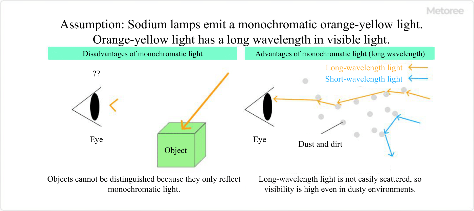
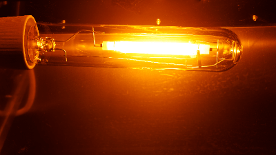
Figure 1. Sodium lamps and visibility
Sodium lamps are often used in roadway, industrial, and commercial lighting applications to save energy. The most famous example is tunnels. Since visibility in tunnels is impaired by exhaust gases and dust, orange-colored sodium lamps, which are less susceptible to these effects, have been used since around the 1960s.
The demand for sodium lamps has been on the decline as regulations on automobile exhaust emissions have been tightened, visibility in tunnels is no longer reduced, and LED lighting has become more widely used. However, because the light from sodium lamps does not easily attract insects due to their nature, they are in high demand as lighting in industries where insect infestation can be a serious problem, such as the food and manufacturing industries.
Principle of Sodium Lamps
Sodium lamps are classified into three types according to their vapor pressure: low-pressure, high-pressure, and high-pressure sodium lamps with high color rendering.
1. Low-Pressure Sodium Lamps
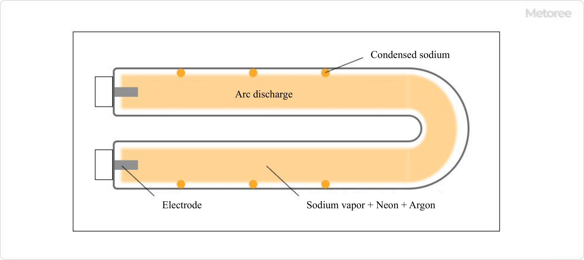
Figure 2. Structure of a low-pressure sodium lamp
The pressure of the enclosed sodium vapor is very low, around 0.5 Pa, and contains trace amounts of neon and argon as light emitting aids. It has the longest history among sodium lamps, and its luminous efficiency is up to 180 lm/W, which is higher than LEDs.
However, they also have drawbacks, such as a monochromatic orange light that makes red objects appear black and a short life span.
2. High Pressure Sodium Lamps
These lamps have improved the color rendering properties of low pressure sodium lamps and are filled with sodium vapor pressure of 0.1 atm. They contain a small amount of xenon as an auxiliary agent for luminescence, and a special alumina ceramic is used for the light-emitting tube to prevent damage even under high temperature and high pressure conditions. Not only is the color rendering property improved, but the luminous lifetime is also about three times longer.
3. High-Pressure Sodium Lamps With High Color Rendering
Compared to high pressure sodium lamps, the vapor pressure of these lamps has been raised to about five times that of high pressure sodium lamps. The color rendering property is greatly improved, resulting in warm lighting similar to that of incandescent lamps.
Although the luminous efficiency is lower than that of other sodium lamps, it is still more than three times more efficient than incandescent lamps.
Other Information About Sodium Lamps
1. Why Sodium Lamps Are Less Likely to Attract Insects
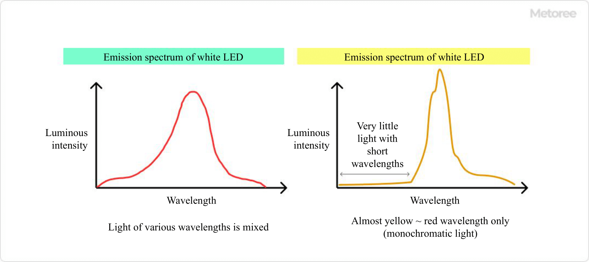
Figure 3. Emission wavelengths of sodium lamps
Insects are attracted to ultraviolet light. Sodium lamps emit light at a wavelength of only around 590 nm and emit a monochromatic yellow light. In other words, the light is imperceptible to insects, making it difficult for insects to be attracted to the lamps.
Because of their monochromatic emission, sodium lamps are not suitable for use in places where color information is required for visual inspections, but they are suitable for use on farm roads and other places where you do not want to attract insects.
2. Points to Keep In Mind When Replacing Sodium Lamps
With the discontinuation of mercury lamps, which emit light based on the same principle as sodium lamps, sodium lamps are being replaced by LEDs. However, sodium lamps have several characteristics due to their emission color.
It is important to select lighting that is appropriate for the site where it will be used, rather than simply substituting white LEDs with a focus on energy savings alone. In recent years, LEDs that reproduce the color temperature of sodium lamps have been developed, so such LEDs should also be considered.