カテゴリー
category_usa

Wire Bonders

What Is a Wire Bonder?

A wire bonder is a device used to electrically bond a large number of I/O electrodes to the substrate side of integrated circuits such as IC chips and LSI chips. Wire bonders are also used to connect electrodes between printed circuit boards.

Although flip chip bonders have been widely used for mounting integrated circuits in recent years, there is still a need for wire bonding.

There are two types of wire bonders: the manual type, in which bonding is performed while observing the bonding with a microscope, and the fully automatic type, in which the bonding address is programmed in advance.

Uses of Wire Bonders

Wire bonders are mainly used in the assembly process, which is the back-end process of the semiconductor manufacturing process. The manual type described above is used for experimental and prototype board circuits, while fully automated wire bonders are used in the mass production process.

Wire bonders require high productivity because they connect electrodes on a one-to-one basis. For this reason, products that connect wires at a high speed of about 0.05p/s per wire bonding location have become mainstream.

Principle of Wire Bonders

Ultra-thin wires made of gold, aluminum, copper, or other materials are used to connect electrodes on the substrate and integrated circuits. Ultrasonic welding technology is used to bond each electrode and wire, and bonding is completed in a very short time. The part where the wires are passed and joined is called the head, of which there are several types depending on its structure.

Since wire bonders require wire bonding between extremely tiny electrodes, the positioning accuracy is extremely precise, requiring an accuracy error of ±2 microns. It also requires precise management and control of the pressing load (bonding load) of the head and is equipped with a non-rebound servo mechanism and anti-vibration system that suppresses external vibrations to achieve high positioning accuracy.

The wire bonding process can be broadly classified into two categories: wire bonding and wire bonding.

Wire bonding can be roughly classified into two methods: ball bonding, in which electric discharge is generated between the wire and electrode, forming a ball-shaped molten part on both sides, followed by pressure bonding while applying heat or ultrasonic waves, in which the wire is directly pressed by ultrasonic waves onto the electrode without forming a ball-shaped molten part. There is a method called wedge bonding, in which the wire is pressed directly to the electrode without forming a ball-shaped melted portion, using ultrasonic waves.

There is a wide range of wire diameters from tens of microns to several hundred microns in ribbon wire, and the bonding method must be selected according to the wire.

カテゴリー
category_usa

Rotary Valves

What Is a Rotary Valve?
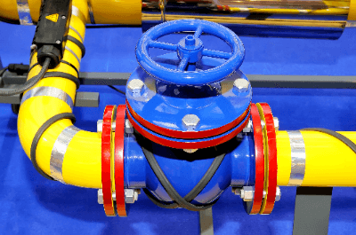
Rotary ValvesA rotary valve is a valve that controls the amount of fluid or powder cutout.

Pneumatic conveying using compressed air is mainly used for conveying powder, but it is necessary to supply a fixed quantity to prevent clogging. However, unlike liquids and gases, the amount of powder cannot be controlled by the opening of a valve, so the cutout volume is controlled by a rotary valve.

Rotary valves are very commonly used in the powder industry, but their disadvantage is that they are large and heavy due to the need for continuous rotation.

Uses of Rotary Valves

Rotary valves are used in industrial equipment. Their main purpose is to control the amount of material cut out.

Specific applications are as follows:

  • Fuel adjustment in coal-fired power plants
  • Cutting out smoke ash from boilers
  • Cutting out food ingredients in food factories
  • Cutting out powdered chemicals at pharmaceutical plants
  • For feeding raw materials in cement plants

Rotary valves are used for feeding powdery materials. They are installed at the bottom of hoppers of pneumatic conveyors and before feeding into agitators. They should be used to control the feed rate, especially for grinding mills, which can become clogged if a large amount of powder enters the mill.

Principle of Rotary Valves

Rotary valves have a different structure from ordinary valves. Inside the valve, there is a rotor with blades, and each blade is divided into sections. As the rotor rotates, it continuously discharges the powder that has accumulated in the partitioned areas. The amount of material discharged can be controlled by the valve size, the number of rotor blades, and the number of rotations.

When the rotor and case come into contact with each other inside the machine, they scrape off each other and mix into the material. This is called contamination. Since this is a major problem in the food industry, countermeasures such as the use of large clearance blades are taken. A magnet can also be installed under the rotary valve to prevent contamination.

Rotary valves require a drive source. Most of them use motors. Therefore, the cutout volume can be adjusted by variable frequency devices such as inverters.

Other Information on Rotary Valves

1. Clogged Rotary Valve

Because the material to be handled by the rotary valve is a powder, clogging may occur. Therefore, clogging countermeasures are mandatory in many cases. Clogging frequently occurs when the powder is sticky. Clogging can also occur when moisture is absorbed during the powder handling process or when lumps that have stuck to the primary side are fed in at once.

Effective countermeasures are to use raw materials with low viscosity or to dry them in the pretreatment process. Another measure is to install a vibrating motor, called a vibrator, to prevent powder from sticking to the primary side of the rotary valve. If the raw material absorbs moisture, measures such as installing tress piping to keep the powder warm can also be taken.

In some cases, the powder may gradually stick to the partitions between the blades of the rotary valve. Some models are equipped with scraper blades. By employing these, it is possible to scrape out the powder so that it does not remain in the partition.

2. Maintenance of Rotary Valve

The following are the general maintenance items for rotary valves:

  • Replacement of packings on the flange surface that seal powder
  • Replacement of gland packing at the shaft seal
  • Replacement of motor and rotor bearings
  • Replacement of drive chain
  • Maintenance of the drive motor

For models with a scraper attached, maintenance of the scraper shaft and replacement of gears are also included.

In case of overhaul, the following deterioration diagnosis is also performed:

  • Measurement of shaft fit
  • Measurement of shaft runout
  • Measurement of the wear condition of the gland packing part

Since the gap between the rotor and casing has dimensions designed by the manufacturer, it is important to check the dimensions from the case to the shaft end before disassembling. Failure to do so may cause contamination due to contact between the case rotor and scraper.
カテゴリー
category_usa

Slide Bushs

What Is a Slide Bush?

Slide Bushes

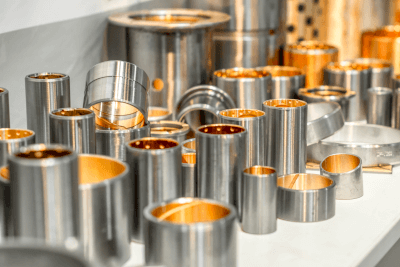
A slide bush is a mechanical component that fits into a shaft or cylindrical member to fill a gap or to provide cushioning.

Slide bushes come in a variety of shapes and sizes, including block, open, triple two-sided, and grease nipple types, and are suitable for a wide range of applications.

As a typical example, the slide bushes manufactured by Nippon Bearing (NB) are designed and made using a round shaft as a guide and a linear motion mechanism that utilizes the rolling motion of balls. This mechanism is simple and features low friction.

Uses of Slide Bushes

Slide bushes are used in automatic recorders, measuring instruments, office automation equipment and peripheral devices, and precision instruments. They are also widely used in tool grinders, automatic glass cutting machines, bunching presses, and food equipment.

In the case of the NB slide shaft, a linear motion system is used in pairs with a cylindrical shaft, and the linear motion with minimal frictional resistance enables light and highly precise motion. Additionally, since the guideway is a round shaft, space can be effectively utilized, allowing for compact machine design. From standard specifications to corrosion-resistant specifications, various combinations can be selected to suit the usage conditions.

Features of Slide Bushes

The features of NB slide bushes are described below.

Main Features

  • Compact Mechanism With Effective Use of Space
    Using a round shaft as a guide allows for effective space utilization.
  • Various Shapes and Mounting Methods
    A wide variety of shapes, including standard, open, and flange types, cater to a broad range of applications.
  • Selection According to the Environment
    Options include standard type, corrosion-resistant, steel, and resin types, allowing selection based on specific requirements.
  • Compatibility
    Shafts can be combined in various ways.
  • Dust Proof
    The double lip seal features an inward-facing lip to reduce grease leakage while maintaining dust-proof properties.
  • Low Friction
    The raceway surface is precision-ground for a smooth finish, with a smaller contact area with the ball, resulting in lower friction than other linear motion mechanisms.
  • GM Series
    The GM series, compared to the SM type, has 30 to 50% less mass.
    Its ball return section, made of resin, ensures quiet operation.
  • Brick Series
    Equipped with a Slide bush, the housing offers a block shape suitable for various installations. The precision-machined block is ideal for high-precision equipment and machinery.
  • FIT Series
    Ensures smooth motion with minimal wobble.
カテゴリー
category_usa

Scissors Gauges

What Is a Scissors Gauge?

Scissors gauges are a type of limit gauges, which are tools used to measure whether the outside diameter of a rod-like object (shaft) is within a predetermined dimension by placing it between the rod and the shaft. They are also called a snap gauge because they are made of a steel plate.

They are tools that have two measuring faces, one on the street side and the other on the stop side, and are used to measure an object by placing it between them.

The standard type has a measuring range of 0 to 1000 mm and a minimum display of 0.01 mm.

There are two types of shapes, single or double-ended, with the single-ended shape being widely used due to its ease of use.

Uses of Scissors Gauges

Scissors gauges are used in various industries, including the automotive industry, electronics, semiconductors, control equipment, and construction.

In particular, they are used to inspect products that require micron-level accuracy, products that require time-consuming inspections due to the existence of multiple measurement items for a single product, and a small number of products.

Examples are as follows:

  • Inspection of engine parts such as measurement of piston shape and outer diameter.
  • Maintenance of automobile internal combustion engines.
  • Parts production for motorcycle modification.
  • Checking the thickness of thin sheets.
  • Inspection of motor shafts.
  • Maintenance of precision machinery and process control systems.
  • Measurements and inspection of machine parts.
  • Repair of agricultural machinery.
  • Measurement of parts with specified tolerance in shaft machining and lathe machining.
  • Thickness measurement of metal plates and blades.

Features of Scissors Gauges

Scissor gauges have a simple structure, with the maximum value of the tolerance of the shaft diameter set at the gauge passage and the minimum value set at the gauge stop. If the shaft diameter does not pass through the passage, the shaft diameter is too large, and if it passes through the stop, the shaft diameter is too small.

Martensitic stainless steels, which have high strength, hardness, and wear resistance through heat treatment, and die steels, which can be hardened to high hardness, are also often used.

カテゴリー
category_usa

Tensile Tester

What Is a Tensile Tester?

A tensile tester is a device that measures the response of a material sample under a tensile load. It evaluates mechanical properties such as tensile stress, strain, Young’s modulus, and Poisson’s ratio, crucial in determining the strength and durability of products.

Uses of Tensile Testers

Tensile testers are essential for assessing the mechanical properties of various materials like metals, plastics, rubbers, and fibers. They are also used in biological studies for testing the strength of tissues such as muscle and bone and in evaluating medical device materials.

Principle of Tensile Testers

Tensile testers operate by applying a tensile load to a specimen and measuring the resulting stress and strain. Key parameters like the proportional limit, elastic limit, yield point, and tensile strength are calculated from the stress-strain curve. The early measurement stage shows proportionality between stress and strain, the mid-term includes the elastic limit and yield point, and the final rupture indicates the sample’s tensile strength.

Types of Tensile Testers

Common types of tensile testers include hydraulic and mechanical universal testing machines:

  • Hydraulic Universal Testing Machine: Performs various static tests by adjusting stress through hydraulic pressure.
  • Mechanical Universal Testing Machine: Known for constant speed testing using servo motors.

Other Information on Tensile Testers

Key aspects of tensile testers include:

    • Units: Stress is measured in Newtons (N), with mN or kN used for different load cell capacities. Before SI units’ enforcement, “kgf” was used, but it has been replaced by “N” in modern standards.
    • Young’s Modulus: Indicates material hardness, with higher values denoting harder, less bendable materials. Steel, for instance, has a high Young’s modulus.
    • Poisson’s Ratio: The ratio of longitudinal to transverse strain, with a value near 0.5 indicating no volume change during deformation, typical for materials like rubber.
    • JIS Standards: There are various JIS standards for tensile testing, tailored to different materials. Adherence to these standards ensures fair and standardized test results.
カテゴリー
category_usa

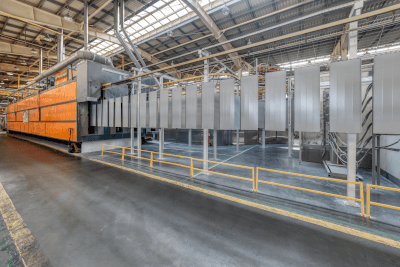
Electrostatic Painting Machine (Electrostatic Coating Machine)

What Is an Electrostatic Coating Machine?

Electrostatic Painting Machine

An electrostatic coating machine is a mass-production paint equipment that performs electrostatic coating, a coating method that uses high-voltage direct current. Electrostatic coating itself has a long history, dating back to the 1930s.

Compared to atomizing coating, where paint is sprayed as a mist, dipping, where paint is immersed in a bath of paint, and pressing-type coating, where paint is applied with a roller or brush, electrostatic coating requires less paint and does not generate air bubbles. This results in a lack of pinholes in the paint film. However, dust and dirt are attracted by static electricity, leading to the need to watch out for “dust and dirt spots,” which are defects in the paint film. Additionally, due to the use of electricity, fire hazards must be carefully managed.

Uses of Electrostatic Coating Machines

Electrostatic coating machines are used not only for mass-produced general-purpose products but also for industrial applications such as automobile painting, as they can efficiently apply a coating film to the object being painted.

Electrostatic coating allows the paint to adhere to the object in a way that atomizing coating cannot achieve, simplifying the process. It has the advantage of being applicable even to areas such as corners where compressed air cannot reach.

While a uniform coating film is achieved, one drawback is that the paint tends to accumulate on convex areas where the electric field is concentrated. Because of the use of electric current, organic solvent-based paints are more suitable than water-based paints.

Principles of Electrostatic Coating Machines

Electrostatic coating machines utilize electrostatic stress as their defining principle. Electrostatic stress refers to the phenomenon in which, when one of the electrodes or the object to be coated is grounded and brought close to the discharge electrode of the coating machine, the electrode opposite to the discharge electrode becomes charged.

When the object to be coated is grounded and a negative electrode is applied, the object becomes positively charged. Increasing the voltage of the discharge electrode of the coating machine causes corona discharge, ionizing the surrounding air and generating an ion current from the discharge electrode to the coated object. The coating droplets in the coater also become charged and are attracted to the coated object by the ionic current, adhering to it, losing their charge, and becoming fixed in place.

By incorporating an air sprayer into the discharge electrode of the coating machine, the paint can be made finer, and the paint droplets can be charged in a shorter time, reducing working time. If a stationary type is used, it is necessary to be vigilant about changes in viscosity due to rising paint film temperatures caused by elevated temperatures and reductions in electrostatic effects due to contamination.

On the other hand, when used handheld, skilled work is required to prevent sparking phenomena when the distance between the electrostatic coating machine and the object to be coated becomes too close.

Disadvantages of Electrostatic Coating Machines

Electrostatic coating can efficiently form a coating film for a large quantity and small variety of products, which is a major advantage. However, the use of static electricity and powder can pose disadvantages.

Uneven Coating and Unique Defects
Electrostatic coating relies on electrostatic stress, so if the shape of the coated object is not uniform, the electric field will be non-uniform, resulting in unevenness. The electric field tends to concentrate on convex areas, causing paint to accumulate there and leading to thicker coatings than on other areas.

Dust and dirt in the atmosphere are also attracted by static electricity, resulting in paint defects known as “dust and dirt spots.” Another defect can occur due to reverse ionization when the voltage is too high.

Achieving Thin Film Thickness Is Difficult
Electrostatic coating machines cannot produce thin films because powder is applied directly as a coating material. The minimum coating thickness is about 30 μm, and attempting to make the coating film thinner can easily result in defects, such as unevenness, necessitating a switch to liquid coating methods, like organic solvent coating.

Challenges in Small-Quantity, High-Variety Production
Electrostatic coating is a lengthy and complex process involving cleaning before coating, paint adhesion, and high-temperature baking drying.

Specialized Coating Equipment and Safety Measures Required
The use of high-voltage electricity and powder demands dedicated coating equipment with safety measures against electric shock and fire, resulting in significant initial investment costs. Apart from coating equipment, drying ovens and other equipment for fixing the coating film and for pre-coating processes to remove oil and rust are also required, presenting another disadvantage.

Management of Paint Powder
As the paint is in powder form, safety measures against dust explosions are crucial, not only during use but also during storage. Powders have a large surface area and are susceptible to oxidation and contamination, potentially leading to defects.

Difference Between Electrostatic and Electrodeposition Coating

The main difference between electrostatic and electrodeposition coating lies in their methods. Electrostatic coating sprays paint and utilizes electrolysis to make the paint adhere, while electrodeposition coating involves immersing the coated object in a paint bath and applying an electric current to deposit a film. Electrodeposition coating is known for its high coating uniformity due to immersion in liquid paint.

カテゴリー
category_usa

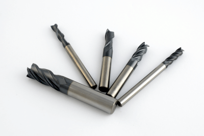
Carbide End Mills

What Is a Carbide End Mill?

Carbide End Mills

Carbide end mills are mainly used on milling machines and drilling machines. They are primarily used to cut hard materials or materials that are difficult to machine. One of the characteristics of cemented carbide is its extreme hardness.

Tungsten carbide is an alloy made by sintering hard metal carbide powder with iron-based metal powder. Various shapes of cutting edges are available, but two-flute and four-flute spiral shapes are commonly used.

Uses of Carbide End Mills

Carbide end mills have advantages and disadvantages that should be considered:

  • Advantages: Compared to HSS, the extreme hardness of carbide end mills enables high-speed cutting, reducing machining time. Additionally, their inflexible and rigid nature prevents bending and shaft expansion, ensuring precise machining.
  • Disadvantages: Carbide end mills are less resistant to strength loss than HSS, which can lead to blade surface defects, among other issues.

Principles of Carbide End Mills

Carbide end mills are used to cut materials that are difficult to machine. The “cemented carbide” in carbide end mills is an alloy made by sintering very hard metallic carbide powder with iron-based metal powder. It exhibits extreme hardness, with a longitudinal modulus of elasticity three times that of iron and an indentation hardness of approximately 90.

Carbide end mills are harder than HSS, the base material, allowing for high-speed cutting, and their inflexible and rigid nature makes them suitable for precision cutting. To use them correctly, it is essential to determine the appropriate machining process based on factors like the diameter and type of the carbide end mill and the material to be cut and machined.

Re-coating and polishing can extend the life of carbide end mills, making them a cost-effective choice despite the higher initial cost compared to HSS. Each piece may be more expensive, but the extended tool life results in lower overall costs.

Carbide End Mill Material

Carbide end mills are cutting tools requiring high hardness and durability. Therefore, the material of cemented carbide end mills is a cemented carbide alloy consisting of extremely hard tungsten carbide (WC) fine particles bonded with cobalt (Co), which is both flexible and hard.

In the manufacturing process, tungsten carbide and cobalt powders are uniformly mixed in a powder mixer, then pressed into the shape of an end mill using a molding die. After that, they are sintered at a high temperature of 1300℃ or higher and completed by hot hydrostatic pressing (HIP) to remove internal defects such as gaps between the powders.

To further enhance wear and heat resistance, hard film coatings like titanium nitride (TiN) and titanium carbide (TiCN) are applied, extending service life. After a certain period of use, the coating thickness decreases, affecting its performance.

Hardness of Carbide End Mills

The hardness of carbide end mills depends on the amount of tungsten carbide and the particle size. A larger amount of tungsten carbide and smaller particle size result in higher hardness but increased brittleness, increasing the risk of chipping and cracking.

Hardness ranges from 900 HV to 1850 HV on the Vickers hardness scale, significantly higher than the maximum value of hardened steel at approximately 860 HV. This wide range allows for hardness selection based on the workpiece properties. Additionally, coating affects not only surface hardness but also heat resistance and chip evacuation properties, necessitating comprehensive judgment based on the carbide end mill’s inherent hardness.

カテゴリー
category_usa

Carbide Drills

What Is a Carbide Drill?

Carbide Drills

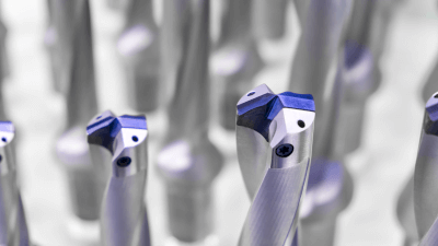
Carbide drills are mainly used on milling machines and drilling machines. They are mainly used to drill holes in hard materials or materials that are difficult to drill. One of the characteristics of cemented carbide is that it is extremely hard.

Cemented carbide is an alloy made by sintering hard metal carbide powder with iron-based metal powder. The shape of the blade portion can be varied, but those with a double-edged spiral shape are generally used.

Uses of Carbide Drills

Uses of cemented carbide drills have advantages and disadvantages:

  • Advantages: Compared to HSS, the extremely high hardness of cemented carbide drills enables high-speed cutting and shortens machining time. Also, the inflexible and very rigid nature of HSS prevents bending and enlargement of holes, enabling accurate machining.
  • Disadvantages: Carbide drills are less resistant to strength loss than HSS, so drill surface defects are more likely to occur.

Principles of Carbide Drills

Carbide drills are used to drill holes in materials that are difficult to machine. “Carbide” (cemented carbide) in carbide drills is an alloy made by sintering a very hard, hard metallic carbide powder with an iron-based metallic powder. It is extremely hard, with a longitudinal modulus of elasticity three times that of iron and an indentation hardness of around 90.

Carbide drills are harder than HSS, the base metal, and therefore can be used for high-speed drilling. Carbide drills are also suitable for precision drilling due to their inflexible and extremely rigid nature. In addition, in order to use carbide drills correctly, it is necessary to confirm in advance the machining process that is suitable for the cutting conditions depending on the diameter and type of drill and the material to be cut, and to perform the machining. Since it is possible to use the drill again by re-coating and polishing, it is recommended to use the drill again. Although each piece is more expensive than HSS, the tool life is longer and the final cost is lower than that of HSS.

Disadvantages of Carbide Drills

Carbide drills are harder and more heat-resistant than HSS drills, so they can drill through difficult-to-cut materials such as titanium and stainless steel, and their high durability gives them a long service life. On the other hand, one of the disadvantages of this drill is that its high hardness makes it less tough and prone to cracking and chipping (chipping) due to brittle fracture. Chipping and breakage can occur when the shank (the part of the handle without a blade attached) slips because the holding power of the tool is weakened. Another disadvantage is that the initial purchase cost is higher than that of HSS drills because tungsten used in cemented carbide is a rare metal and extremely expensive. On the other hand, since it can cut at high speeds and has an even longer service life, the running cost is lower, which may result in lower total cost.

Cutting Stainless Steel With Carbide Drills

Since stainless steel is harder and more tenacious than common steel, Carbide drills, which are harder than HSS drills, are used. Carbide drills for stainless steel are not only made of different materials, but also have a cutting edge angle of 135 degrees, higher than the 118 degrees of HSS drills, to reduce contact resistance during cutting. The core thickness is also made thinner to reduce resistance.

Breaking of Carbide Drills

Carbide drills are harder than HSS drills, but their toughness is inferior. Causes of breakage include “increased cutting resistance,” “seizure and softening,” and “tilting.” The deeper the cutting hole, the harder it is for the cutting fluid, which serves as cooling and lubrication, to reach the drill, and the more likely it is that the drill and workpiece will seize. In addition to this, the temperature rises due to frictional heat, which softens the drill itself, making it easier to break. When the hole is deep, cutting debris cannot be discharged properly and gets stuck, which also causes increased cutting resistance. Another cause of breakage is the shear force exerted on the drill by an inexperienced operator who tilts the drill in the middle of cutting. Drills are strong against longitudinal forces but weak against shear lateral forces, so care must be taken in cutting conditions.

カテゴリー
category_usa

Vertical Drilling Machinery

What Is Vertical Drilling Machinery?

Vertical drilling machinery is a machine tool used for drilling holes in materials like metal, wood, plastic, and ceramic. It operates with a vertically aligned drill bit, with the workpiece table positioned perpendicular to the bit.

This machinery can drill holes of different sizes and shapes by changing the drill bit. It’s essential for high-precision processing and can be adapted for various materials by switching drill bits, making it versatile for a range of applications.

Uses of Vertical Drilling Machinery

Applications of vertical drilling machinery include:

  • Drilling holes in metal parts, furniture parts, etc.
  • Making screw holes in metal and aluminum plates.
  • Groove carving and surface finishing on metal and plastic parts.
  • Surface finishing of parts by sanding and other techniques.
  • Drilling and cutting cemented carbide parts.
  • Drilling fine holes in electronic components and circuit boards.

Principle of Vertical Drilling Machinery

The process includes:

  1. Securing the material on the drilling table using a clamp or vise.
  2. Installing the appropriate drill bit into the drill chuck.
  3. Setting the right rotation speed and feed rate for the drill bit and material.
  4. Starting the drilling operation by rotating the spindle and applying the drill bit to the material.
  5. Periodically checking the progress and depth of the drilling.
  6. Completing the drilling process and removing the drill bit from the material.
  7. Releasing the material from the clamps or vise after drilling.

Structure of Vertical Drilling Machinery

Essential components include:

  1. A sturdy base made of cast iron or steel for stability.
  2. The spindle, which holds and rotates the drill bit.
  3. The drill bit, a rotating cutting tool available in various sizes and shapes.
  4. The drill chuck, used to secure drill bits of different sizes to the spindle.
  5. A table for holding the material in place, adjustable for precision.
  6. A belt pulley that transmits motor power to the spindle.
  7. An electric motor for spindle rotation, with adjustable speed.

Types of Vertical Drilling Machinery

Various models include:

  1. Small tabletop drilling machines for light work and simple drilling tasks.
  2. Larger, floor-standing drilling machines for industrial applications and heavy workloads.
  3. Radial drilling machines with horizontally movable drill heads, suitable for complex drilling tasks.
  4. Multi-function drilling machines for tasks like drilling and milling.
  5. CNC drilling machines with computer numerical control for precise and complex machining.

Additional Information on Vertical Drilling Machinery

Advantages of vertical drilling machinery include:

  • High accuracy in drilling holes, with precise control over hole depth and diameter.
  • Simple operation, making it accessible for beginners.
  • Versatility in handling various materials and tasks, including grinding, polishing, and cutting with multifunctional models.

Disadvantages include:

  • Large footprint, requiring significant space in the work area.
  • Primarily focused on drilling, limiting its suitability for other machining operations.
  • Time-consuming for tasks involving a large number of holes.
  • Less suited for machining precise angles and complex shapes.

Vertical Drilling Machinery Drive System

Drive systems include:

  • Belt Drive Type: Uses a belt to transmit power from the motor to the spindle, with speed variations achieved through different pulley combinations.
  • Gear-Drive Type: Employs a gear mechanism for power transmission, offering high torque and precise control, suitable for heavy-duty tasks.

The choice between belt-driven and gear-driven systems depends on specific machining requirements and the work environment.

カテゴリー
category_usa

Surface Inspection Systems

What Is a Surface Inspection System?

A surface inspection system is a device used to inspect products on factory production lines.

It is mainly used to identify defective products and detect defective parts.

Uses of Surface Inspection Systems

Surface inspection systems are used in various fields for product inspection. For example, they are used in the inspection of continuously produced products such as film, glass, and metal plates.

A surface inspection system helps prevent the shipment of defective products by detecting defects based on image data obtained from capturing images of each product’s surface. However, the inspection criteria vary depending on the product.

For products where smoothness is crucial, such as film and glass, the system detects unevenness, while for metal plates, it targets fine scratches for detection.

Principle of Surface Inspection Systems

A surface inspection system detects defects using image data captured by a camera. It consists of an inspection section with a light receiver and a light projector, and a control section for image processing, including a computer. A CCD camera is generally used as the light receiver in the inspection section.

The projector, acting as the light source, may use various types of lamps such as fluorescent, LED, and halogen lamps, depending on the application. The light from the source, the floodlight, is reflected or transmitted on the object’s surface, captured by the CCD camera, and converted into an electrical signal.

The signal from the CCD camera is processed in the control unit to detect defects in the image data. This involves comparing the data with that of a defect-free product and identifying a defect when a variation exceeding a threshold is confirmed. For instance, surface inspection systems used in printing traditionally employed analog waveforms instead of image data.

This method sometimes failed to detect thin defects or misjudged the ground tone as a defect. Using image data resolves these issues by enabling detailed analysis based on pixel size.

Other Information on Surface Inspection Systems

1. Light Reflection and Transmission in Surface Inspection Systems

In surface inspection systems, light from a projector is reflected or transmitted on the surface to be inspected. The five types of reflection and transmission are direct reflection, diffuse reflection, direct transmission, diffuse transmission, and scattering transmission.

Each method has distinct characteristics, making it essential to choose the appropriate method for detecting either “flaws” or “irregularities” during surface inspection.

2. Camera and Projector in Surface Inspection Systems

The accuracy of the camera in the inspection section of a surface inspection system is a critical factor. A camera with insufficient accuracy may miss detecting abnormal areas.

The performance of the projector, which illuminates the object under inspection, significantly influences the camera’s imaging performance. To ensure uniform illumination on the object’s surface, a bar light with a diffuser is often used. Additionally, using a grating light (slit light) allows the inspection of curved surfaces and the detection of minute defects.

3. Image Processing in Surface Inspection Systems

In a surface inspection system, the light captured by the CCD camera’s lens is projected as image data onto the image sensor and transmitted to the image processing computer in the control section. Image processing typically involves pre-processing, measurement, determination of abnormality, and output.

The image data captured by the sensor often contains noise, which is reduced through pre-processing techniques like smoothing, edge extraction, and shrinkage. The computer then compares the processed image data against a set of criteria to determine abnormalities and outputs the results.

Cameras used in surface inspection systems are usually highly accurate with a large pixel count. However, a high pixel count necessitates extensive pre-processing, requiring a computer with a high-performance CPU.