カテゴリー
category_usa

Spring Contact Probe

What Is a Spring Contact Probe?

A spring contact probe is an electrically conductive probe.

A spring contact probe can be used to inspect the continuity of printed circuit boards and electronic components without the need for soldering, connector connection, or other fixing. The shape of the probe can be selected according to the inspection target.

The spring-loaded structure allows the probe to make contact with the electrode to be inspected with an appropriate load.

Uses of Spring Contact Probes

A spring contact probes are used for continuity testing of electronic components.

The inspection targets include semiconductors, liquid crystal panels, circuit boards, connectors, capacitors, sensors, batteries, and other components.

In addition to simple inspections of disconnections and shorts in these components, spring contact probes can be used in a wide range of applications, such as current flow and high-frequency measurement. For example, to inspect ICs, spring contact probes are placed on the printed circuit board on the side of the inspection equipment and contacts the IC from above, enabling quality inspection without fixing it in place.

カテゴリー
category_usa

Oscilloscope

What Is an Oscilloscope?

Oscilloscope

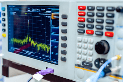
An oscilloscope is an instrument that outputs electrical signals as waveforms on a screen, and is characterized by the ability to observe signal changes over time in two dimensions.

Oscilloscopes are broadly classified into analog oscilloscopes and digital oscilloscopes.

1. Analog Oscilloscopes

Analog oscilloscopes observe input signals by scanning an electron beam over the tube surface of a cathode-ray tube to draw waveforms. The input signal to the oscilloscope is immediately displayed with a short delay.

2. Digital Oscilloscopes

Digital oscilloscopes convert input signals into digital data using an A/D converter, store the data in memory, and then display the waveforms on a display. Unlike analog oscilloscopes, data collection is discrete, so data is complementary and displays as a smooth curve.

Uses of Oscilloscopes

Oscilloscopes display electrical signals as waveforms, allowing you to visually check the operation of electronic circuits. By using an oscilloscope, it is possible to check the signal waveforms in an electronic circuit and verify that the circuit is operating as intended.

When verifying high-speed digital circuits, signals must be captured with reliable timing that is not affected by digital signal fluctuations (jitter), and oscilloscopes are used to set the timing.

Oscilloscopes are also useful in repairing electronic equipment because they can trace the signal waveforms of various parts of an electronic circuit to locate the faulty part if the cause of the equipment failure is in the electronic circuit.

Principle of Oscilloscopes

In a conventional analog oscilloscope, the signal input from the probe is transmitted to the oscilloscope’s vertical amplification circuit. The signal is attenuated or amplified in the vertical amplifier circuit and then transmitted to the vertical deflector plate of the cathode-ray tube.

The voltage applied to the vertical deflector plate scans the electron beam up and down. This sequence of events is the principle behind oscilloscopes. The input signal is simultaneously transmitted to the trigger circuit, and the electron beam starts scanning horizontally the moment the signal matches the set trigger condition.

In a digital oscilloscope, the input signal is converted to digital data by an A/D converter, and the data is sequentially stored in memory. Then, after a predetermined period has elapsed from the point when the input signal meets the trigger condition, it stops storing new data.

As a result, the above memory records the signals before and after the timing when the trigger condition is met, and these signals are displayed as waveforms on the display. In other words, signal waveforms before the trigger can also be observed.

The data in the memory can also be used for waveform analysis, e.g., frequency analysis of signals by FFT operation. Furthermore, the data can be output to a memory card for analysis and data storage on a PC.

How to Select an Oscilloscope

When selecting an oscilloscope, it must have sufficient specifications for the application. Specifically, frequency response, sampling rate, number of channels, memory length, and available probe types should be considered.

In addition to the basic use of oscilloscopes for observing waveforms, current oscilloscope applications are expanding to include timing verification, waveform analysis, and compliance testing, and the measurement range and functionality are increasing accordingly. As a result, there is a need to select a model with functions suitable for the intended use.

How to Use an Oscilloscope

In addition to observing voltage variations over time, oscilloscopes can also measure the frequency of repetitive signals and draw Lissajous curves. Oscilloscopes are widely used for testing electronic circuits, waveform visualization of video and audio signals, testing response characteristics of power devices, measuring the timing margin of high-speed digital circuits, and evaluating mechatronics products.

Preparation for measurement includes phase adjustment of probes and skew adjustment between probes. Especially when current and voltage probes are used together, skew adjustment is essential because of the significant delay time of current probes. One should also wait about 30 minutes after power-on before measuring to ensure sufficient measurement accuracy.

The trick to observing the desired waveform is to adjust the trigger. With analog oscilloscopes, the only adjustment factors are slope selection, trigger level, and trigger delay, but with digital oscilloscopes, in addition to these factors, various trigger conditions, such as pulse width and interval, can be set.

Additionally, sequential triggers, which capture signals when multiple trigger conditions are satisfied, are also available.

Other Information on Oscilloscopes

1. Features and Differences Between Analog and Digital Oscilloscopes

The features of both types of oscilloscopes can be summarized as follows:

Analog Oscilloscope

  • Excellent real-time performance and short dead time between capturing and displaying a new signal.
  • The frequency of occurrence of the same waveform can be determined by the brightness of the signal.
  • Not suitable for observation of one-shot phenomena or phenomena that are not frequently repeated.
  • Requires photographic equipment to save observation results.
  • Analysis using waveforms is not possible.

Digital Oscilloscope

  • The supplemental display of one-shot phenomena is possible.
  • Observation results can be handled as electronic data for easy storage.
  • Waveforms can be handled as digital data and analyzed by a processor.
  • Long dead time for signal processing, so actual observation time is relatively short.
  • Waveform frequency information is lost in repetitive waveforms.

Today, there are no analog oscilloscopes available for industrial measurement applications, and digital oscilloscopes are the choice for almost 100% of applications.

This is possible because of readily available high-speed A/D converters and processors for waveform processing, along with tech improvements that address digital oscilloscope limitations, resulting in affordable, highly functional products.

2. Points to Note About Oscilloscopes

There are several points to note when using an oscilloscope to observe correct waveforms. In particular, it is important to select a model with a frequency response that sufficiently covers the frequency band you wish to measure.

The frequency response of an oscilloscope is defined as the frequency at which the amplitude falls to -3 dB. So, for accurate amplitude measurement, a model with a frequency response of about 5 times the frequency of the signal under test should be selected.

Additionally, the data sampling frequency of a digital oscilloscope must also be taken into consideration. If the sampling frequency is less than twice the frequency of the signal under test, aliasing will occur and false waveforms will be displayed.

カテゴリー
category_usa

Logic Analyzer

What Is a Logic Analyzer?

Logic Analyzers
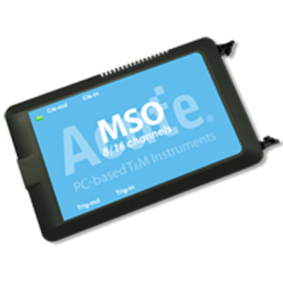
A logic analyzer is a device primarily used to verify the operation of digital circuits.

They are sometimes compared to oscilloscopes, which are mainly used for analyzing analog signals.

Uses of Logic Analyzers

Logic analyzers are essential tools for verifying and troubleshooting digital circuits and are used in product development and manufacturing.

For multiple signal inputs, analog characteristics are not measured, but converted to 0s and 1s using threshold values for further processing. Since signals are treated as digital data, logic analyzers are used in the following applications:

  • Debugging and verification of system operations.
  • Simultaneous tracking and correlation of multiple digital signals.
  • Detection of timing violations and transients on buses.
  • Tracing the execution of embedded software.

Logic Analyzer Principles

A probe is connected to the measurement point of the system under test (SUT) and the signal is transmitted to the logic analyzer, first passing through the internal comparator.

The comparator compares the signal to a threshold voltage set by the user, and if the measured voltage exceeds that of the threshold voltage, the signal is transmitted to the next stage as a 1; if the voltage is lower than the threshold voltage, the signal is transmitted as a 0. In other words, after passing through the comparator, the signal is treated as digital.

The result is output as a digital signal corresponding to the clock and trigger conditions. The clock can be either the internal sampling clock of the logic analyzer or the SUT’s clock, depending on the application.

The former is done to obtain timing information between each signal, and the latter to obtain state. Trigger conditions can be set for various items such as specific logic patterns, number of events, and event duration.

It is important to set appropriate threshold values based on the signal level of the circuit being tested, and to set appropriate clock and trigger conditions for the information to be obtained.

How to Use the Logic Analyzer

Connect the probe to the SUT and set names for individual input signals. When measuring multiple signals such as buses, it is easier to observe the measurement results if they are grouped and registered.

Next, determine the sampling time. The higher the sampling clock frequency, the more detailed the signal measurements become. On the other hand, the amount of data that can be captured is constant, so the time range that can be observed becomes narrower. The signal sampling interval can be obtained from the following equation.

Sampling interval (sec) = 1/frequency (Hz)

Finally, set trigger conditions. In addition to defining triggers, the display method for when a trigger occurs can be specified. This allows you to specify whether to stop sampling after a trigger occurs once or to update the results each time a trigger occurs.

Other Information on Logic Analyzer

1. The Difference Between a Logic Analyzer and an Oscilloscope

While oscilloscopes can observe analog characteristics such as signal waveforms, logic analyzers handle digital data from signals.

Although oscilloscopes provide more information from a single signal, they can only observe about four signals simultaneously, whereas logic analyzers can handle many input signals at the same time. 

2. Points to Note When Using a Logic Analyzer

There are a few precautions to take when using a logic analyzer to prevent damage to the SUT or logic analyzer itself and to obtain accurate measurements.

Make sure the SUT is turned off.
When connecting a probe to the SUT, there is a risk of contact between the measurement point and its surroundings via the probe; if the SUT is powered, a large current may flow at that moment and cause failure. Therefore, the SUT should only be turned on after the probe is connected.

Select the probe appropriate for your application.
There are three types of probes:

  • Flying-lead probes connect a separate lead to each signal to be measured.
  • Connector probes connect to a connector dedicated to the logic analyzer.
  • Connectorless probes connect directly to the footprint of the board.

Select the probe that best suits your application.

Set the measurement conditions according to the application.
Set the sampling clock and recording time according to the frequency of change of the signal to be measured and the measurement range. Depending on the performance of the logic analyzer, select the settings and model to obtain correct measurement results based on the resolution and memory capacity.

カテゴリー
category_usa

Solder Pot

What Is a Solder Pot?

Solder PotsA solder pot is a container that holds or is filled with molten solder and equipped with a heater to keep the solder in a molten state.

Depending on the shape and quantity of the object to be soldered, solder pots range in size from tabletop units for use in laboratories to large units for use on production lines.

There are two types of solder pots: stationary units, in which the solder remains stationary inside the pot, and jet-flow solder pots, in which there is a nozzle inside the pot and the solder flows out in jets.

Uses of Solder Pot

Solder pots are well suited for tasks such as soldering leads and mounting components on printed circuit boards. While soldering may be done manually, solder pots are useful for efficiently soldering large volumes of simple, stable objects and achieving consistent results.

Principle of Solder Pots

Solder pots consist of a container for storing molten solder and a heater for keeping the solder in a molten state. Their basic structure is simple, but most solder pots used in production environments are equipped with a conveyor that can precisely control the temperature of the solder pot and transport objects into it.

The molten solder in a solder pot oxidizes when exposed to air for a long period of time. Oxides deteriorate the wettability between the solder and the base metal to be soldered, which is a major cause of solder defects.

It is important to always supply molten solder that is not oxidized to achieve good results. This is why jet-flow solder pots, in which a nozzle spurts molten, unoxidized solder from inside the solder pot into contact with the base metal, are often preferred.

Although measures to remove oxides are necessary with both stationary and jet-flow solder pots, oxides are less likely to form when using the latter because the solder is always flowing, reducing the amount of work required to remove oxides.

1. Soldering Using a Stationary Solder Pot

Molten solder is placed in the solder pot, and the component to be soldered is immersed in the molten solder. Soldering is completed when the component is pulled out.

2. Soldering Using a Jet-Flow Solder Pot

Jet-flow solder pots are equipped with a nozzle that is used to spray molten solder onto the component.

This method has become widespread in the field of printed circuit board manufacturing. An example of a common automated process is when a chip is built into a printed circuit board, and transported to the solder pot by a conveyor, where jets of molten solder mount it in place.

Other Information on Solder

1. Types of Solder

When using solder, a flux is used to ensure a clean soldering process.

Flux is a liquid containing ammonium chloride or zinc chloride. It is used to remove impurities from the printed circuit board and clean the surface of the board so that it can be soldered cleanly. It is also used to prevent oxidation of the copper wiring on the board surface.

Rosin is a component of pine tar that acts as a flux. It is often incorporated into solder called rosin core solder.

2. Solder Material

Solder is an alloy consisting mainly of lead and tin. Solder is mainly used to make metal bonds between various electronic components and connectors mounted on printed circuit boards, which constitute electronic circuits, and the wiring on the printed circuit boards to enable the conductivity of the components and connectors. Another common application is to facilitate metal bonding between pipes.

The history of solder dates back to around 3000 BC in Mesopotamia. Silver-copper or tin-silver solder was used to attach silver handles to copper vessels. Later, during the Greek and Roman periods, tin-lead solder, which is now the mainstream solder, was used for joining water pipes.

Later, the toxicity of lead became apparent, and the EU became the first country in the world to regulate the use of tin-lead solder via the Rohs Directive of 2006. Today, solder and electronics manufacturers around the world are taking the lead in developing lead-free solders, which are now widely used. Currently, the main solder alloys are tin-silver-copper, tin-copper-nickel, and tin-zinc-aluminum, none of which contain lead.

3. Solder Temperature

The temperature of solder varies depending on the solution, but the melting point of lead-containing solder is 183 °C and that of lead-free solder is around 210 °C. Lead-free solder has a higher melting point, making it more difficult to melt and spread.

However, products comparable to the conventional tin-lead type have now been developed, and the melting points of tin-silver-copper (Sn 96.5%, Ag 3%, Cu 0.5%) and tin-copper-nickel (Sn 99%, Cu 0.7%, Ni and other additives) alloys, which are some of the most common lead-free solders, are 217-227 °C.

カテゴリー
category_usa

Vibration Tester

What Is a Vibration Tester?

A vibration tester is a testing machine that applies vibration to parts or products.

The main purpose is to check for damage or failure caused by vibration. It is also used to examine the vibration response characteristics of components.

Any product can be damaged due to fatigue caused by vibration over a long period. Therefore, vibration tester is often used for quality assurance purposes.

A vibration tester is mainly used to check vibration resistance performance by sinusoidal or random wave vibration. They are also used to measure mechanical impedance, which is the vibration response characteristic of a mechanical system, to determine resonance frequencies and vibration countermeasures.

Uses of Vibration Testers

Vibration testers are used to confirm the vibration resistance of parts and products and to determine the vibration response characteristics of components and structures.

Principle of Vibration Testers

Vibration testers are classified into mechanical, hydraulic, electrodynamic, servo motor, and other types depending on the drive system. The classifications are as follows.

1. Mechanical Vibration Testers

This method uses a motor as the driving force to mechanically convert rotational motion into reciprocating motion. Compared to hydraulic and electrokinetic types, mechanical vibration testers are relatively inexpensive. In recent years, mechanical vibration testers have been replaced by other methods due to their shortcomings in controllability. 

2. Hydraulic Vibration Testers

This method uses hydraulic pressure from a hydraulic pump as the driving force. The servo valve switches the hydraulic circuit at high speed to generate vibration. This method is suitable when low vibration frequency, long stroke, and high power are required. The frequency range is 1 to 300 Hz. It is often used when large structures such as buildings are vibrated by seismic waves.

3. Electrokinetic Vibration Testers

This method utilizes the Lorentz force generated when an electric current is applied to a conductor in a magnetic field. By bypassing an alternating current through a drive coil installed in a magnetic field with an excitation coil, a reciprocating motion is generated in response to the current. The vibration of the shaker is detected by a pickup and fed back to the controller to keep the vibration at a set value. This method is characterized by a wide range of vibration frequencies and can be used up to particularly high vibration frequencies. The vibration frequency range is generally from 5 to 3,000 Hz, but some small shakers are capable of higher frequencies, up to 40,000 Hz. 

4. Servo Motor Type Vibration Testers

This method uses a servomotor linear actuator that combines an AC servomotor and a ball screw to generate vibration. The load capacity is lower than that of the hydraulic type, and the frequency range is lower than that of the electrodynamic type. The operating range is intermediate between the hydraulic and electrodynamic types. The frequency range is 0.01 to 300 Hz.

カテゴリー
category_usa

Leakage Current Meter

What Is a Leakage Current Meter?

A leakage current meter is a device that measures leakage current from electrical equipment. Generally, it is a clamp meter that can measure minute currents of mA or less.

Uses of Leakage Current Meters

Leakage current meters are used in electrical equipment and medical devices. Generally, they are used to determine whether they conform to the standards outlined in laws and regulations.

Leakage current has a significant impact on the human body, and even a weak leakage current can lead directly to death, so accurate measurement is necessary from a safety perspective. It is also important from the viewpoint of quality because it can cause noise in communication equipment.

Principle of Leakage Current Meters

Leakage current meters are capable of non-contact measurement with circuit conductors and measure current by clamping a copper wire with a clamp meter.

The principle of current detection is to detect the magnetic field generated by the current and extract an output proportional to the measured current. The most common detection methods include the CT method, Rogowski coil method, Hall element method, and fluxgate method.

The principle of each method is as follows.

1. CT Method

This method converts the current to be measured into a secondary current corresponding to the turn ratio.

2.Rogowski Coil Method

This method converts the voltage induced in an air-core coil by an alternating magnetic field created around the current to be measured.

3. Hall Element Method

This method combines the Hall element and CT methods to measure from DC current.

The Hall element is an element that measures the voltage generated when a current flows through a point where a magnetic field is generated, and this method is the mainstream for DC measurement.

4. Fluxgate Method

This method combines the fluxgate (FG element) and CT methods to measure DC current.
The fluxgate is an element that measures the magnetic field generated by winding two coils in opposite directions around an iron core and calculates the current value backward from the magnetic field.

Difference Between Leakage and General Ammeters

The most important feature of a leakage current meter is its resolution.

Ammeters that measure load currents measure large currents of 1A or more in the case of the clamp method. leakage current meters, on the other hand, need to measure weak currents, so they can only measure weak currents of 1A or less.

There are load current meters that measure weak currents for semiconductor manufacturing processes, but for such applications, devices that are connected in series to a circuit are commonly used.

カテゴリー
category_usa

Ultrasonic Sensor

What Is an Ultrasonic Sensor?

Ultrasonic Sensors

An ultrasonic sensor is a device that uses ultrasonic waves to measure the distance to an object.

Ultrasonic is a general term for sounds that have a high frequency and cannot be heard by humans. The human ear can detect frequencies between 20 Hz and 20,000 Hz, but sounds of higher frequencies are not audible to humans and are called ultrasonic.

Ultrasonic sensors generate ultrasonic waves and measure distance by detecting the reflected sound waves. In recent years, ultrasonic sensors have become more compact, lightweight, and inexpensive, and are therefore widely used.

Uses of Ultrasonic Sensors

Ultrasonic sensors are widely used in household and industrial applications. For everyday use, the advantage of non-contact distance measurement is utilized in such ways as in-vehicle rangefinders and jet towels. In-vehicle distance meters are rapidly becoming popular due to the mandatory use of collision damage reduction brakes.

Industrial applications include level gauges for wastewater tanks and chemical storage tanks. They are often used for highly corrosive liquids.

Fish finders also use ultrasonic sensors. This is an application of ultrasonic sensors that have been used for a long time.

Principle of Ultrasonic Sensors

Ultrasonic sensors measure distance by transmitting ultrasonic waves and detecting the reflected waves.

The speed of sound is determined by the atmosphere in which the sound, and is estimated to be 340 m/s in air and 1,500 m/s in water. If the propagating atmosphere is known, the distance can be converted by measuring the time it takes for the reflected wave to reach the receiving element.

The main component of ultrasonic sensors is the piezoelectric element. The piezoelectric element converts electrical energy into kinetic energy, and then back into electrical energy when pressure is applied via the reflected wave.

Therefore, the piezoelectric element performs both transmitting and receiving functions. It converts the input electrical signal into ultrasonic waves, senses the reflected waves, and outputs an electrical signal.

In principle, the advantages and disadvantages of ultrasonic sensors are as follows.

Advantages of Ultrasonic Sensors

  • Non-contact detection of object distance
  • Can detect transparent objects such as glass
  • Possible to pass through even if there is some dirt or dust between the object and the sensor
  • Ultrasonic waves are fast, so the sensor can detect moving objects

Disadvantages of Ultrasonic Sensors

  • Easily affected by temperature and wind
  • Soft and bumpy objects cannot be detected

The most important feature of ultrasonic sensors is that they can measure distances without contact. They are mostly used when non-contact measurement is required.

カテゴリー
category_usa

Digital Multimeters

What Is a Digital Multimeter?

Digital Multimeters

A digital multimeter is generally used to measure basic electrical characteristics such as DC voltage, AC voltage, DC current, and resistance. Higher-end models can measure more exotic power profiles, including those that capture complex AC-based data. For example, AC (Alternating Current) power is frequency-based. High-end digital multimeters are capable of capturing peak currents and average currents, which are stored at different positions on an AC waveform. This kind of data can be used to troubleshoot impedance issues, power factor correction problems, and much more.

On the device, while conventional voltmeters, ammeters, and resistance meters have analog displays in which the meter pointer indicates the measured value, a digital multimeter is called a digital multimeter because it has multiple measurement functions and three- to eight-digit numerical displays. Models with extended measurement functions such as capacitance, AC frequency, and temperature are also available.

Compact and lightweight models suitable for use at construction sites are also called digital testers. The number of digits displayed is about 4 digits, and the measurement accuracy is generally 0.05 to 0.1% for DC voltage and 0.5 to 1% for AC voltage. Although the accuracy is insufficient for precise measurements in the laboratory, they are easy to use for outdoor applications. In anticipation of such use, models with a sturdy construction to withstand drops are also available.

Uses of Digital Multimeters

Digital multimeters are used in a variety of situations, including measurements in laboratories, electrical adjustment of products on factory production lines, and construction and maintenance inspections of electrical facilities.

They are often incorporated into power-receiving equipment and power control panels. In such cases, in addition to basic parameters such as current, voltage, and resistance, some have built-in functions to measure capacitance, frequency, and temperature.

In addition to the specialized applications described above, inexpensive models are also available for use in general household electronic construction.

Principle of Digital Multimeters

The core of a digital multimeter (DMM) consists of a high-precision, high-resolution analog-to-digital converter (A/D converter) and a processor that calculates measurement values based on digital output. The A/D converter converts the analog signal acquired by the test procedure into a digitally recognizable measurement that’s then processed by a microchip. The means of collecting the analog measurement data are described as follows.

1. DC Voltage Measurement

The voltage between two probes is converted to a voltage within the dynamic range through an amplifier or attenuator that affects the voltage by either amplifying it (for low voltage) or attenuating it (for high voltage) to become the input voltage that’s transferred to the A/D converter. The processor calculates the voltage between the probes based on the digital value, amplifier gain, and attenuation factor of the attenuator, and displays the DC voltage value on the display unit.

2. AC Voltage Measurement

The AC voltage is converted to DC voltage through a rectifier circuit, then input to the A/D converter, and the AC voltage value is displayed on the display unit through the same process as DC voltage.

3. Resistance Measurement

A constant current is applied to the resistance to be measured through two probes from the constant current power supply built into the digital multimeters. The DC voltage appearing at both ends of the probes is input to the A/D converter to measure the voltage at both ends of the resistor to be measured. From this voltage value and the current value of the constant-current power supply, the processor calculates the resistance value to be measured.

4. Current Measurement

To measure DC current, the voltage at both ends of the micro resistor generated by the measured current flowing through in the digital multimeters is input to an A/D converter. The processor calculates the current value from the output value of the A/D converter and displays the current value on the display unit. For AC current, the AC voltage at both ends of the micro resistor is converted to DC voltage by a rectifier circuit and input to the A/D converter.

5. A/D Converter

The A/D converter of digital multimeters requires very high precision (high resolution), e.g., 24 bits or more for a 7-digit display, so a double-integral type is generally used. Therefore, the time required for conversion is relatively long, and several measurements per second is the most that can be done. However, by reducing the number of displayed digits and shortening the conversion time of the A/D converter, it is possible to shorten the measurement time.

How to Use the Digital Multimeters

A description of how to use digital multimeters follows

1. Voltage and Current Measurements

In digital multimeters, the system to be measured is connected between the two input terminals, the Hi and Lo terminals. When measuring DC voltage, connect the Hi terminal to the high voltage side and the Lo terminal to the constant voltage side, and the voltage on the Hi terminal side will be displayed based on the potential on the Lo terminal side. When measuring DC current, if the current to be measured flows in from the Hi terminal and out from the Lo terminal, the current value is displayed as positive, and in the opposite direction, it is displayed as negative. In AC voltage, current, and resistance measurements, polarity need not be taken into consideration.

2. Measurement Range Setting

For general use, the AutoRange function automatically switches to the optimum range for the voltage and current within the maximum input rating, so there is no need to search for the optimum range. However, if you need to reduce measurement time, such as when adjusting a production line, you will need to manually set the range based on the expected measurement value.

3. Effect on the Circuit to be Measured

Connecting digital multimeters may affect the system under measurement and cause fluctuations in measured values. For example, if digital multimeters are connected to a circuit with very high impedance, such as when measuring the output voltage of an optical sensor in a dark environment, its internal impedance may load the measurement system, resulting in a lower value than the original output voltage.

Similarly, when measuring the current of a circuit with a small impedance, the minute resistance for voltage detection present in the digital multimeters may cause a non-negligible error in the circuit under measurement. Therefore, the influence of the digital multimeters on the circuit under measurement should be considered before deciding whether or not to use digital multimeters.

4. Low Resistance Measurement

There are digital multimeters that can perform 4-terminal measurements for resistance measurement. As the term “4-terminal” implies, it consists of a pair of constant-current power supplies and a pair of voltmeters. A constant-current power supply is connected to both ends of the resistor to be measured. The voltmeter is connected to the constant-current terminals of the resistor to be measured.

The voltmeter measures the voltage at both ends of the resistor by placing a probe inside the constant-current terminals, at a point on the resistor side. The resistance is calculated from this measured voltage and the constant current value. Since the contact resistance of the constant-current terminal does not affect the measured voltage and the contact resistance of the probe of the voltmeter is negligible compared to the internal resistance of the voltmeter, which is typically as high as 10-MΩ, low resistance can be accurately measured.

カテゴリー
category_usa

Semiconductor Inspection Equipment

What Is Semiconductor Inspection Equipment?

Semiconductor inspection equipment
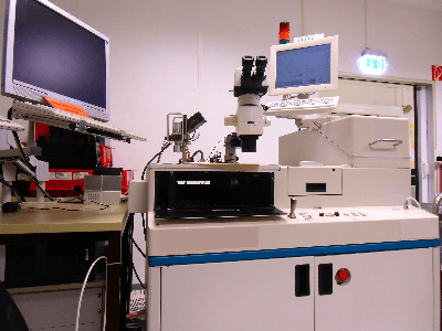
Semiconductor inspection equipment is equipment that inspects wafers and semiconductor chips for defects in the semiconductor manufacturing process.

The main semiconductor manufacturing processes include the photomask manufacturing process, which is equivalent to a printing plate, the wafer manufacturing process, which is the foundation of semiconductors, the front-end process of forming fine circuit structures on wafers using photomasks, and the back-end process of packaging individual semiconductor chips after circuit formation. If we look at the details, there are hundreds of processes.

In recent years, semiconductor microfabrication technology has reached the nanometer range (about 1/10,000th the thickness of a human hair), and at the same time, wafers have become larger in diameter, so that several thousand semiconductor chips containing billions of transistors can be produced from a single wafer.

Inspection equipment is extremely important in the semiconductor manufacturing process, which boasts such high productivity, leading to early rejection of defective products, cost reduction, and improvement of quality and reliability. The criteria for selecting semiconductor inspection equipment should take into consideration the diameter of the wafer, the process to be used, and the type of defects to be detected.

Uses of Semiconductor Inspection Equipment

Semiconductor inspection equipment is used in various phases of the semiconductor manufacturing process.

Defects to be detected using semiconductor inspection equipment include distortion, cracks, scratches, and foreign matter on photomasks and wafers, misalignment of circuit patterns formed in the front-end process, dimensional defects, packaging defects in the back-end process, and many other cases.

For this reason, it is necessary to select appropriate semiconductor inspection equipment and software for each process, and automation using AI, etc. is being promoted to speed up inspections and reduce manpower.

Principle of Semiconductor Inspection Equipment

Semiconductor inspection equipment consists of measurement equipment, software to process the measured data, and facilities to perform the appropriate measurement.

High-resolution cameras, electron microscopes, and laser measuring instruments are used as measuring devices. Software for processing the measured data is developed with algorithms that are specific to the process to be inspected. Vibration suppression and lighting equipment are also necessary to ensure proper measurement. The image imaging, image processing, and defect classification technologies that are central to semiconductor inspection equipment are described below.

  • Image Imaging Technology
    Image imaging technology measures defects by irradiating a laser beam onto a wafer and then detects the scattered light. By illuminating minute irregularities, foreign matter and damage can be detected.
  • Image Processing Technology
    Image processing technology is a technology that detects defects by comparing adjacent patterns, utilizing the fact that the patterns formed on all chips on the wafer are the same. It is capable of high-speed and wide-area processing.
  • Defect Classification Technology
    Defect classification technology is a technology that, after detecting a defect, classifies the defect and extracts the cause. This technology is necessary to identify and address the causes of defects.

Types of Semiconductor Visual Inspection

1. Visual Inspection in Wafer Manufacturing Process and Front-End Process

Wafers are made from semiconductor raw materials such as silicon, which are formed as cylindrical monocrystalline materials called ingots, sliced to a thickness of about 1 mm, and polished on the surface, with a diameter of 12 inches (about 30 cm) these days.

Defects in wafers include not only attached foreign matter but also surface flaws, cracks, uneven processing, and crystal defects on the wafer itself, etc. Detecting these defects mainly by laser beam irradiation is the visual inspection in the wafer manufacturing process.

The front-end process proceeds in the wafer state, and there are two main types of defects that occur there, referred to as random and systematic. Random defects are mainly caused by the presence of foreign matter, but because they are random, their locations are unpredictable. Therefore, random defects on wafers are detected by image processing. Systematic defects, on the other hand, are defects caused by particles adhering to the photomask or exposure process conditions, such as on the photomask, and tend to occur at the same location on each semiconductor chip lined up on the wafer.

2. Visual Inspection in the Back-End Process

In the back-end process, wafers are cut into individual chips (dicing), placed in resin or ceramic packages, and sealed by connecting terminals on the chips to those on the package (wire bonding). The second stage of the process consists mainly of electrical inspections, but also includes visual inspections for wire bonding defects, part number printing defects, etc.

Other Information on Semiconductor Visual Inspection

1. Importance of a Semiconductor Visual Inspection

In general, visual inspections in the manufacturing process often aim to check for dirt, scratches, etc., and in some cases have nothing to do with product functionality or performance. However, dirt, scratches, etc. in semiconductor manufacturing are not merely apparent problems; in almost all cases, they are problems that affect functionality and performance.

Semiconductors are electronic devices, and like other electrical and electronic devices, electrical inspections are performed. However, it is extremely difficult to inspect all the billions of transistors and the wiring that connects them, and only visual inspections can confirm things like transistor gates and wiring detail.

2. Accuracy of a Semiconductor Visual Inspection

In semiconductor processes at the nanometer level, the thickness of a single wire and the spacing between adjacent wires are several nanometers.

If there are nano-order defects here, they can cause wiring shorts or wire breaks. Furthermore, even if the wiring width is 90% of the designed value due to a defect of 1/10th the size, the resistance and capacitance of the wiring will change. When an electric current flows through this wiring, a phenomenon called electromigration, in which metal atoms move due to the movement of electrons, occurs, rapidly thinning the wiring and causing disconnections to occur in a short period.

Thus, semiconductor manufacturing requires visual inspections with extremely fine precision, and as microfabrication technology continues to evolve, the required precision will continue to increase.

カテゴリー
category_usa

AC Power Supply

What Is an AC Power Supply?

AC power stands for alternating current power. It refers to power that changes direction and magnitude with frequency. Distributed network power, the lines that supply industries, commercial ventures, and homes all use AC power.

All electric power supplied by power companies to ordinary households is AC power. Air conditioners, refrigerators, lighting fixtures, and other home appliances that are plugged into electrical outlets all run on AC power. It’s the same with industrial premises: motorized pumps, large-scale refrigeration units, and even the control systems that manage all of these larger electrical machines, all supply AC power. Sometimes that power is supplied as a single-phase line, sometimes as a three- or four-phase line power supply, but it still travels as a frequency-regulated alternating current AC power supply.

In industrial applications, devices that convert direct current (DC) to alternating current are also called AC power supply and are widely used. Inverters may be required for these to run correctly.

Uses of AC Power Supplies

AC power supplies are used in a wide range of applications, from general home appliances to industrial equipment.

Many household appliances, such as hair dryers, air conditioners, and microwave ovens run on AC power. Kitchen appliances, multimedia devices, and wall sockets, all operate on AC power. Most industrial equipment, such as commercial refrigeration units, ventilation blowers for exhaust air, and industrial water pumps, are also powered by AC.

In the IT industry when referring to an AC power supply, the term uninterruptible power supply (UPS) is sometimes used. Uninterruptible power supplies are used to protect critical data servers and data storage. AUPS is a product that supplies AC power while charging the battery with commercial power during normal times, and supplies power from the battery when the commercial power goes out. An inverter is added to a UPS to ensure the batteries inside the unit are charged with DC power.

UPS is also used to supply uninterrupted AC power to precision equipment. Data servers are one example of such critical and precise equipment. Even the slightest disturbance of the AC power supplies can cause them to malfunction, making UPS essential. 

Simulators are also available to test whether electrical equipment can be damaged by intentionally creating disturbances in the AC power supply.

Principles of AC Power Supplies

Commercial AC power is mainly supplied by synchronous generators. Synchronous generators use electromagnetic induction to supply power.

Electromagnetic induction is the principle that voltage is generated when a magnet is placed close to or away from a conducting solenoid (such as a wound copper wire). Synchronous generators create electric power by the voltage generated from rotating the windings at high speed while generating a strong magnetic field inside. A mechanically induced source of kinetic energy supplies rotor-generated force. As that force acts on a rotor, the generator stator receives magnetically induced power. The speed of the generator decides the initial frequency of the AC power.

AC (regulated) power supplies in the IT industry can be broadly classified into two types: AC stabilizer type (AVR) and frequency converter type (CV/CF).

1. AC Stabilizer Type

The AC stabilizer type stabilizes the output voltage and waveform, while the frequency converter type also stabilizes the frequency.

AC stabilizer systems are broadly classified into SLIDAC systems and tap-switching systems. The SLIDAC method uses a servomotor (servo motor) or a similar device to continuously switch the taps of a transformer to maintain constant AC voltage.

The tap-switching method compares the voltage of the input AC current with a reference voltage, corrects the error, and outputs the result.

2. Frequency Converter Type

Frequency converter systems are broadly classified into linear amplifier systems and inverter systems. In both methods, the AC current is converted to a DC current.

The output voltage and frequency are then corrected using a linear amplifier (linear amplifier method) and a DC/AC inverter (inverter method) and put out as AC power supplies.

Advantages of AC Power Supplies

There are two major advantages of AC power supplies as follows.

1. Easily Transformable

AC power supplies can be easily transformed according to the winding ratio of the transformer. Long-distance power transmission can be done at high voltage to reduce losses, and power can be easily extracted by placing a transformer at the demand location.

Although it is possible to convert voltage using a DC power supply, the cost of the converter itself and the time required for the conversion are high. The greatest advantage of AC power supplies is that this method of adjusting voltage can reduce the equipment cost of power transmission and distribution. 

2. Easy Circuit Breakdown

AC power is characterized by cyclically alternating a positive and negative voltage. If you want to stop the current temporarily in the event of an accident or disaster, you can use the moment of zero current to interrupt the circuit, thereby minimizing damage to the electrical system and the circuit breaker itself.

Other Information on AC Power Supplies

Invention of AC Power Supplies

AC power supplies were invented by an inventor named Nikola Tesla. Tesla was born in what is now the Republic of Croatia and excelled in mathematics from an early age.

While a student at the Technical University of Graz, he saw a “gram generator” (a device for generating a direct current that functions as both a generator and a motor), which inspired him to think about ways to improve power generation. Five years later, he succeeded in inventing the world’s first AC current generator, the two-phase AC motor.

Tesla then developed his ideas on alternating current and went on to work for Thomas Edison, who was famous for inventing direct current. However, Edison was against Tesla’s invention of the AC current.

Both Edison and Tesla appealed to the usefulness and safety of the current they had invented, and a “DC current Edison vs. AC current Tesla” configuration was later created. After this confrontation, Tesla’s alternating current was recognized by the public, and today alternating current is indispensable.