Programmable Delay Lines

What Is a Programmable Delay Line?

A programmable delay line is a type of electronic circuit called a delay line that delays the propagation time of an electrical signal.

The delay time can be changed by programming. In addition, there are passive delay lines consisting only of passive elements and active delay lines that can be driven by external ICs.

By delaying a signal for an arbitrary amount of time, it is possible to match the timing with other signals or to intentionally add a time difference. They are used in a wide variety of electronic devices, including communications equipment.

Uses of Programmable Delay Lines

Programmable delay lines are used to match the timing of data and clock signals. It is especially important to be able to adjust the timing precisely, since the higher the speed, the more likely it is that slight timing deviations will cause problems.

Other applications include signal pulse width conversion, oscillator circuits, frequency multipliers and frequency discriminators. Applications include medical, broadcasting, military, and space. Programmable delay lines are used in various detection and communication devices where precise timing is required.

Principle of Programmable Delay Lines

A programmable delay line is a simple principle that uses inductance L and capacitance C to delay the propagation of electrical signals. It is considered difficult to create a delay line that delivers a specified delay time with high accuracy even when conditions such as process, temperature, and voltage change.

One way to improve accuracy is through feedback. The error against the specified delay time is determined and fed back to the delay line to reduce the error. The delay time is controlled by adjusting the supply voltage, for example. Higher voltage can shorten the delay time.

One way to determine the delay error is to convert the voltage to a frequency. Inverting the output of the delay line and feeding it back to the input produces a frequency output of 1/2 the delay time. This mechanism is called a voltage controlled oscillator (VCO).

Structure of a Programmable Delay Lines

A programmable delay line consists of a delay line that delays a signal and a multiplexer that selects a desired delay time. There are several ways to construct a delay line, and currently the most used is a ladder-type transmission network with inductance L and capacitance C.

The delay time for an N-stage ladder-type circuit is √(L x C) per section, or N x √(L x C) in total. Another configuration is to use a voltage-controlled delay line (VCDL) in which the propagation delay time of the logic gates is controlled by the supply voltage.

The desired delay time can be obtained by selecting an arbitrary stage of the ladder-type circuit with an address signal at the multiplexer. When using programmable delay lines, it is important to consider characteristics such as accurate delay time, good frequency and phase characteristics, low loss, and good temperature characteristics to meet the performance and bit count required for the application.

Other Information on Programmable Delay Lines

1. Characteristic Impedance

Delay lines are transmission lines like coaxial cables and have inherent transmission impedance. The characteristic impedance is a parameter that depends on the inductance and capacitance in the circuit. It is important that the characteristic impedance be uniform within the delay line in order to transmit with minimal waveform distortion. 

2. Rise Time

The rise time inherent in a delay line limits the minimum transmission pulse width. Narrower pulse widths have higher frequency components and therefore require faster rise times.

The pulse width that can pass through the delay line without difficulty must be at least three times the rise time inherent in the delay line.

カテゴリー
category_usa

Remote Control

What Is a Remote Control ?

A Remote Control is a unit that receives optical signals from remote control transmitters used to control various devices in various situations, including AV equipment such as TVs.

Specifically, it receives optical signals from remote control transmitters, converts them into electrical signals, amplifies the signals, and converts them into digital signals. This signal is output and sent to a microcontroller or other device control device incorporated in a subsequent stage.

Uses of Remote Control

Remote controls are used in pairs with remote control transmitters and are widely used in home appliances and audio equipment. Typical examples of such applications are AV equipment such as TVs, Blu-ray and HDD recorders and players, audio equipment such as AV components, and home appliances such as air conditioners and lighting fixtures.

In the case of a typical TV, almost all functions of the device can be controlled by the remote control transmitter, such as power on/off, volume control, channel selection, input switching, menu display and selection, and so on. Therefore, these functions are converted from optical to electrical signals by the remote control in order to output signals from the transmitter to the microcontroller for control of the TV unit.

Principle of Remote Control

The principle of the remote control is that it receives modulated optical signals transmitted from the remote control transmitter and, after demodulation, converts the received optical signals into digital signals for output to transmit control signals to the microcontroller at a later stage.

The wavelength of the light emitted to the remote control receiver unit is usually near-infrared light of 940 nm or 960 nm. The remote control transmitter transmits the original signal modulated at 37.9 KHz to limit the signal ON period to a few percent in order to extend the battery life of the remote control. It is this modulated light that is received by the remote control.

The remote control receives the light at the light receiving element, amplifies this signal, demodulates the modulated wave at 37.9KHz, and outputs it as a digital signal of 3 to 6V. This is to match the operating voltage of the power supply voltage of the microcontroller, etc. connected in the subsequent stage. The microcontroller receiving the remote control signal analyzes the contents of the signal and controls the device according to the results.

There are several types of data formats used in remote control signals. All of these formats use similar light wavelengths and modulation frequencies, but they have different data structures so that they do not interfere with each other’s signals and cause malfunctions.

Characteristics of Remote Control

The items listed as features of a remote control often refer to a receiver circuit corresponding to Band I as specified by the EIAJ, but may also include one corresponding to Band III. The output of a photo diode that receives near-infrared modulated light sent from a remote control transmitter becomes a weak signal when it detects reflected light from a long distance or from a wall, but becomes a very large signal when operated from close range of the equipment.

Therefore, the amplification circuit that receives the signal is required to have a wide dynamic range of 80 dB or more, which is achieved by the built-in AGC. Since light emitted by lighting fixtures can have an adverse effect as noise, the photo diode is covered with a resin that has visible light cutoff characteristics (near-infrared light is transmitted) to eliminate the effect of lighting fixture light.

Furthermore, a bandpass filter with a steep pass-through characteristic is provided to avoid the influence of inverter fluorescent lamps, which blink at high frequencies. The output terminal of the remote control is typically an open collector to match the power supply voltage of the processor that receives the output signal, and a pull-up resistor is provided at the processor’s input terminal to receive the signal.

Other Information on Remote Control

1. Noise Suppression of Remote Control

If the environment in which the remote control is used contains noise sources (e.g., ambient light noise from inverter fluorescent lamps, power supply ripple, electromagnetic noise from power supply circuits, etc.), the remote control receiving distance may be shortened by such noise sources. Therefore, it is necessary to devise ways to avoid them.

While power supply ripple and noise contamination of the power supply circuit can be addressed in the circuit design, preventing the effects of fluorescent lamps requires structural innovations such as blocking light from the ceiling direction.

2. Precautions for Using Remote Control

The remote control has a very high gain, so it is sensitive to noise. Therefore, if the remote control has a shield case, it is important to connect it to the GND securely.

Most remote control modules are designed to be used indoors. When used outdoors, the current output of the photodiode becomes extremely large when sunlight shines on it, saturating the amplifier circuit that receives it and making it impossible to receive near-infrared light from the remote control transmitter.

Therefore, for equipment used outdoors (e.g., cameras and other photographic equipment), a remote control with specifications to prevent saturation by sunlight should be used.

カテゴリー
category_usa

Lithium Battery

What Is a Lithium Battery?

A lithium battery is a type of chemical battery that produces electricity through a chemical reaction. Although the name is similar to that of a lithium-ion battery and is easily confused, a lithium-ion battery is a rechargeable battery based on an intercalation reaction that uses a carbon material capable of storing lithium ions as its negative electrode.

Lithium batteries, on the other hand, use metallic lithium or lithium alloys for the negative electrode and are generally non-rechargeable primary batteries.

Click here for a detailed description of lithium batteries and a list of 36 manufacturers.

The positive electrode of a lithium battery can be made of manganese dioxide, graphite fluoride, or iron disulfide. Typically, when we refer to a lithium battery, we mean a lithium manganese dioxide battery.

Uses of Lithium Batteries

Lithium has the greatest tendency to cationize among all metals and is also the lightest metal. For this reason, lithium batteries are characterized by high voltage, light weight, and high energy density. They are widely used as internal power sources for clocks and memory backup in various household electrical equipment such as Blu-ray/DVD recorders, digital cameras, game consoles, rice cookers, and communication devices.

Some types also have stable discharge characteristics, long-term reliability, and excellent shelf life at high temperatures. This makes them widely used as power sources for various types of water, electricity, and gas meters and smart meters, fire alarms, security equipment, medical equipment, and other important devices.

Principle of Lithium Batteries

Lithium batteries use manganese dioxide, graphite fluoride, or iron disulfide for the positive electrode, lithium metal for the negative electrode, and an organic electrolyte made by dissolving lithium salts in an organic solvent as the electrolyte.

Lithium metal on the negative electrode is ionized from the point where it contacts the electrolyte and dissolves into the electrolyte as lithium ions, and one electron is generated for each lithium atom lithiated. The electrons then move to the conductor and the lithium ions move from the negative electrode to the positive electrode via the electrolyte, causing a chemical reaction with the cathode material.

Characteristics of Lithium Battery

Compared to other batteries such as alkaline batteries, lithium batteries have the following features:

1. Light Weight and High Voltage

While alkaline batteries have a nominal voltage of 1.5 V, manganese dioxide batteries, which are widely used, have a higher nominal voltage of 3 V. Lightweight and high-voltage, they have a high energy density and can be used in smaller devices by reducing the number of batteries from two or more to just one.

2. Low Self-Discharge and Long Battery Life

The cathode of a lithium battery is a chemically stable material that does not deteriorate easily and can maintain more than 90% of its capacity even after 10 years of storage.

In addition, a comparison of battery life in equipment requiring relatively high current (e.g., photographic equipment) shows that lithium batteries can be expected to last about twice as long as alkaline dry cell batteries. Although lithium batteries are more expensive than dry batteries, the frequency of battery replacement decreases, which may be advantageous in terms of total cost for equipment that requires a large amount of current.

However, when used in devices with low current consumption, such as calculators and TV remote control transmitters, the difference in life expectancy between lithium batteries and dry cell batteries is small, with no significant advantage.

3. Wide Temperature Range

Since the electrolyte of alkaline batteries and other batteries widely used in dry cell batteries is an aqueous solution, the reaction activity decreases in low-temperature environments. If the electrolyte freezes, the battery will not function as a battery. For this reason, the recommended operating temperature range for alkaline batteries is 5°C to 45°C.

On the other hand, lithium batteries use an organic electrolyte, which has a very low freezing point. They are also relatively stable at high temperatures, so power can be extracted over a wide temperature range. The operating temperature range for ordinary products is claimed to be -30 to 70°C, and for heat-resistant types, -40 to 125°C.

Because of these characteristics, lithium batteries are used as power sources for equipment in snowy mountaineering and for cameras and other equipment used for photography and video recording.

Types of Lithium Batteries

Generally speaking, lithium batteries are primary batteries that cannot be charged or discharged, but there are also secondary lithium batteries that can be charged and discharged. The following is an introduction to each type:

Primary Lithium Battery

Commercially available primary lithium batteries are classified into three types by shape: cylindrical lithium batteries, coin-shaped lithium batteries, and pin-shaped lithium batteries.

  1. Cylindrical Lithium Battery
    Cylindrical lithium batteries are characterized by low self-discharge and high power output. Graphite fluoride or manganese dioxide is mainly used as the cathode material, and the output voltage is nominally 3V. Graphite fluoride has excellent long-term shelf life and is used as a power source in smart meters for gas and water. Manganese dioxide is suitable for supplying large currents and is used in photographic equipment such as cameras. Lithium batteries using iron sulfide as the positive electrode material have an output voltage of about 1.5 V and are sold as replacements for AA and AAA batteries.
  2. Coin-Type Lithium Battery
    The cathode material of coin-shaped lithium batteries is graphite fluoride or manganese dioxide. Characterized by their thinness and compact size, they are used as backup power sources for memory and clock functions in electrical products and information equipment. They are also used in keyless entry systems and ultra-compact lights in automobiles.
  3. Pin-Type Lithium Battery
    Pin-type lithium batteries are long, thin, and small, and their positive electrode material is graphite fluoride. Applications include electric floats for fishing and small radio wave transmitters.

Lithium Battery

While lithium batteries are generally primary batteries that cannot be recharged, there are also lithium secondary batteries that can be recharged by using a compound such as vanadium or titanium as the positive electrode and lithium metal or a lithium compound or alloy such as aluminum or titanium as the negative electrode, in coin form.

Not only do they have the same excellent characteristics as primary lithium batteries, but they also have excellent charge-discharge cycle characteristics. They are suitable for devices that do not want to or cannot replace lithium batteries midway. Examples of use are in solar-powered watches and backup power supplies for wristwatches.

カテゴリー
category_usa

Industrial Scale

What Is an Industrial Scale?

Industrial Scales

Industrial scales are measuring instruments used to weigh things in the production and development of products, whether in agriculture, forestry, fisheries, or industry.

There are various types of industrial scales, ranging from electronic balances used for precise weighing in laboratories, such as chemical analysis, to floor scales that are embedded in the floor and used to weigh large trucks. Furthermore, there are various types depending on the intended use and measurement environment, such as:

  • Dust-proof specifications for weighing powders.
  • Waterproof specifications for weighing light liquids.
  • Explosion-proof specifications for weighing in hazardous locations such as where explosive gases are generated.

Industrial Scale Applications

Industrial scales are used in a variety of industries to determine weights. Specifically, they are used in laboratory laboratories in the chemical field for research and development and analysis, in the agriculture, forestry, and fishery industries, in production plants for industrial products, and in warehouses in the logistics industry.

In the production and logistics industry, they are used to determine the quantity of products. For example, to count the number of small screws, the weight of about 100 pieces can be stored in advance on an industrial scale, and the number of products can be determined simply by placing them on the scale.

Industrial scales are also incorporated in a series of automated manufacturing processes, such as the automatic filling of liquids and powders, filling volume inspection, weighing for batch processing, blending, and dispensing. Industrial scales are used in a variety of fields, including the pharmaceutical, cosmetic, chemical, and food industries.

Principle of Industrial Scales

General scales include spring scales based on Hooke’s law and balances based on the principle of leverage, but industrial scales mainly use electromagnetic, load cell, and tuning fork measuring principles.

1. Electromagnetic Industrial Scales

The internal structure of an electromagnetic industrial scale is similar to that of a balance. A sample is placed on one side of the rod, and an electromagnetic coil is placed on the opposite side of the rod across the fulcrum.

The electromagnetic force required to maintain equilibrium for the weight of the sample is measured, and the electromagnetic force is converted to weight. The electromagnetic method enables measurement with high accuracy and is suitable for analytical balances and other scales that measure minute samples.

2. Load Cell Type Industrial Scale

This type of industrial scale is composed of a strain gauge that detects the distortion of the load cell and a body that is distorted by the weight of the body. One side of the body is fixed, and a sample is placed on the other side.

The strain generated by the weight of the sample is extracted by the strain gauge as a resistance value and converted to weight. The structure is relatively simple and inexpensive. This method is suitable for measuring heavy objects when high precision isn’t required.

3. Tuning Fork Industrial Scale

Tuning fork industrial scales measure the frequency of oscillation of a sample when a load is applied to a transducer consisting of two connected tuning forks, and convert the frequency to weight. This is a relatively new measuring principle, and its measurement accuracy is somewhere between that of the electromagnetic and load cell types.

Other Information on Industrial Scales

1. Platform Scale

Platform scale is the general term for a scale that measures the weight of a stationary object by placing it on a platform. The platform is designed to sink due to the weight of the object placed on it, and the extent to which it sinks is measured as the weight of the object.

There are a variety of products for a wide range of purposes and capacities. Examples include household scales, kitchen scales, store scales, scales for measuring the volume of propane gas, and truck scales, which have a structure with a weighing platform on the floor and can carry a large vehicle by itself.

In addition to the spring-loaded analog type, there are also a wide variety of products with various uses, weighing capacity, and price ranges. Examples include scales with load cells, electromagnetic sensors, digital types with digital numeric displays, and waterproof and explosion-proof builds.

2. Weighing Table

This is the name of the weighing pan or platform on which the object to be measured is placed in a weighing instrument. Depending on the manufacturer, it is sometimes called a weighing platform as a product name for a platform weigher. 

3. Electronic Balance

An electronic balance is mainly for measuring mass. Some models have a built-in balance structure, while others have a one-block structure without a balance structure. The measurement methods of electronic balances include the electromagnetic force balancing method, load cell method, and tuning fork vibration method.

The electromagnetic force-balancing method was the most common type of electronic balance in the early days, but the strain gauge load cell type is now widely available. In general, the measurement accuracy of the electromagnetic force balancing method is higher than that of the load cell method.

カテゴリー
category_usa

Industrial Endoscopes

What Is an Industrial Endoscope?

An industrial endoscope is an instrument that allows observation of areas that cannot be seen with the naked eye, such as narrow spaces and winding pipes.

A camera is attached to the end of a long, thin probe. The camera is positioned on the part to be observed, and the inside of the part can be observed through the eyepiece, or images can be projected on a main monitor or PC for real-time observation of the inside of the part.

It is necessary to select an appropriate endoscope depending on the observation target, application, and operating environment, such as resolution, depth of focus, length of the probe and main unit, flexibility of the probe, number of light sources, and operable temperature range. There is also a function that allows video images to be recorded, which is useful for later confirmation and data management.

Furthermore, recent models of industrial endoscopes are equipped with a high-performance camera and LED light, which can provide clearer images.

Uses of Industrial Endoscopes

Industrial endoscopes are widely used in industrial fields, such as automobiles, aircraft, power plants, and infrastructure, such as gas and water supply.

1. Automotive, Aircraft, Railroad, and Marine Fields

Internal inspection of engines, hydraulic parts, injection nozzles, turbines, etc.

2. Electric Power Industry

Maintenance and inspection of condensers, piping, turbines, etc. in nuclear and thermal power plants

Civil engineering and construction

Maintenance of bridges, diagnosis of steel frames, observation of under floors and ceilings, etc.

Infrastructure

Inspection of rust, corrosion, blockage, etc. of piping in water and gas facilities

Principle of Industrial Endoscopes

An endoscope consists of three components: an illumination mechanism, a camera, and an image processing function. At the tip of the endoscope, a mirror surface or optical lens is placed, which transmits the image to the camera. An optical fiber cable protected by a rigid tube or flexible sheath is used to transmit light.

Endoscopes are used for nondestructive testing to evaluate the condition of internal components and structures, and images can be displayed in real time during the inspection.

They are extremely difficult to operate and must be operated by technicians with specialized training.

Types of Industrial Endoscopes

An industrial endoscope consists of a main body and a probe, some of which have a monitor, some of which can be connected to a PC, and some of which look through an eyepiece.

Industrial endoscope types include videoscopes, fiberscopes, and rigid endoscopes.

1. Videoscopes

A small dedicated camera is mounted on the tip of the videoscope’s probe, which enables real-time viewing on a dedicated display, smartphone, or other device. At the same time, still images can be taken, and some can measure the length of the object.

In addition to being waterproof, they can also be used to examine the inside of underwater equipment and piping.

2. Fiberscope

Fiberscopes are mainly used for nondestructive inspection and repair. They are characterized by the use of probes made from thousands to tens of thousands of flexible fibers.

Each fiberglass fiber collects light and provides an image through an eyepiece on the opposite side. Since each glass fiber acts as a camera, the resulting image reflects the shadow of the glass fiber’s honeycomb structure.

3. Rigid Mirror

The image obtained by the objective lens is transmitted by a relay lens. The probe part of the relay lens is a metal tube and cannot be bent. It is characterized by its simple structure and easy operation.

Rigid mirror endoscopes consist of a light source, optical fiber, lens, and camera, and are used in the medical field for surgery, treatment, and observation of lesion sites.

Features of Industrial Endoscopes

1. Many Functions

An industrial endoscope is equipped with a variety of useful functions. Some products allow zooming on the monitor, or have a temperature sensor and alarm function at the end of the camera cable.

Others have a hands-free microphone for saving audio and video, an ultra-bright white LED on the tip to set the brightness of the subject as desired, and a flash function using LEDs, making them useful devices for a wide range of applications. This is a convenient device that allows you to choose the functions that best suit your needs.

In addition, many products can output data to a PC or TV monitor, making it possible to share images with multiple people. 

2. High Heat Resistance

Some industrial endoscope products have high heat resistance, which makes them suitable for observing the inside of pipes and machinery. For example, the temperature of automobile engine oil can sometimes greatly exceed 100°C, and it is desirable to use endoscopes with heat resistance of up to 200°C.

カテゴリー
category_usa

Liquid Level Indicator

What Is a Liquid Level Indicator?

Liquid Level Indicators

A Liquid Level Indicator is an instrument that measures the height of the liquid level inside a container or tank.

In some cases, it can also measure the amount of powder remaining. It is also sometimes called a Level Meter.

Various measurement methods have been developed, including float, tube, and ultrasonic types, depending on the object to be measured and the conditions of use. Accuracy and reliability are important for Liquid Level Indicators.

Since incorrect liquid level measurements can affect the production process, Liquid Level Indicators must be maintained and calibrated on a regular basis. With proper care, accurate liquid level measurements can be obtained over the long term.

Applications of Liquid Level Indicators

Liquid Level Indicators are used in a wide variety of industries and applications:

1. The Petroleum Industry

The petroleum industry uses Liquid Level Indicators to manage fuel inventories and schedule deliveries. They are also used as sensors to detect fuel leaks. 

2. Food Industry

In the food industry, Liquid Level Indicators are used in the production of milk, cheese, and other products. They are used to control product quality and determine the fullness of containers, thereby contributing to the improvement of the efficiency of the entire production line.

3. Chemical Industry

Liquid Level Indicators can be used to measure the liquid level of containers for liquid chemicals. It is used for process control and quality control.

Principle of Liquid Level Indicator

Liquid Level Indicators measure liquid levels by utilizing buoyancy, pressure, and electrical phase differences. More accurate Liquid Level Indicators have been developed by combining these principles and adding innovations.

1. Buoyancy Type

Buoyancy-type liquid level gauges measure the liquid level by using a floating body. 

2. Phase Difference Type

In the phase difference type, a high-frequency electrical signal is sent into the liquid, and the phase difference between the signal reflected at the boundary between the liquid and gas is measured to determine the liquid level.

3. Pressure Type

The pressure type measures the liquid level by measuring the pressure generated by the weight of the liquid.

Types of Liquid Level Indicators

There are various types of Liquid Level Indicators, depending on the measurement method. The following are examples of Liquid Level Indicator types:

1. Float Type Liquid Level Indicator

Liquid Level Indicator measures the liquid level using a float called a float. The float, which contains a magnet, floats on the liquid surface and outputs a signal. The measuring principle is similar to that of a ball tap used for flushing toilets, etc., and often has an electrical contact output for use in control.

Float Level Indicators can be broadly classified into two types: wind-up and non-wind-up. Retractable types include spring-balanced and counterweighted types, while nonretractable types include arm float and ball float types.

2. Tube Liquid Level Indicator

Liquid Level Indicator is a tube attached to the outside of the container that is linked to the height of the liquid surface. If the tube is made of glass, the liquid level can be visually confirmed from the outside. The installation of Liquid Level Indicators should be considered when designing tanks and containers.

Liquid Level Indicators are used in a wide range of applications, such as for measuring the liquid level in boilers and water tanks. 

3. Ultrasonic Liquid Level Indicator

This is a method of measuring the liquid level by transmitting ultrasonic waves toward the liquid surface and measuring the time taken for the waves to reflect back. This method is characterized by the fact that the Liquid Level Indicator does not come into contact with the liquid to be measured and by the fact that it can be easily installed.

Since the ultrasonic type requires the signal to be converted to liquid level, it is common for such a system to be equipped with a control board for calculation. Continuous measurement is possible and often has an analog output signal. 

4. Differential Pressure Type Liquid Level Indicator

Liquid Level Indicator converts the pressure difference between the bottom and top of the tank to be measured into the liquid level. It cannot be easily retrofitted because the liquid density must be known and a measurement outlet is required at the bottom of the tank.

However, since it can be used for sealed tanks, it is widely used for pressure tanks such as boilers. 

5. Capacitance Type Liquid Level Indicator

An electrode is inserted into the tank, and changes in the electrostatic capacitance on the electrode are detected and converted to liquid level. It is characterized by its ability to be used in harsh environments such as high temperatures and high pressures.

How to Select a Liquid Level Indicator

It is important to select a Liquid Level Indicator that is appropriate for the type and characteristics of the liquid. If the liquid is corrosive or at high temperatures and pressures, a pressure Liquid Level Indicator with high durability and high accuracy is suitable. On the other hand, if the liquid is volatile, a Buoyancy Liquid Level Indicator or a Phase Difference Liquid Level Indicator is suitable.

Measurement accuracy is another important factor. The required measurement accuracy varies depending on the nature and temperature of the liquid to be measured. When selecting a Liquid Level Indicator, it is important to select the appropriate measurement accuracy.

The type of Liquid Level Indicator should also be selected according to the installation location. A small Liquid Level Indicator is suitable for installation in a small space. There are also Liquid Level Indicators with special shapes to fit the complex shapes of tanks.

The functional aspects of Liquid Level Indicators should also be considered. Selecting a Liquid Level Indicator with remote control and data logging capabilities will allow for efficient operation and monitoring.

Phototransistors

What Is a Phototransistor?

Phototransistors
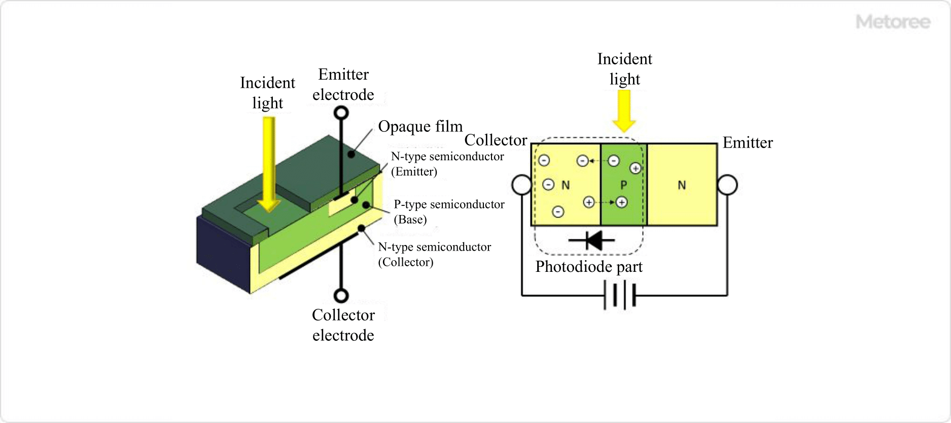
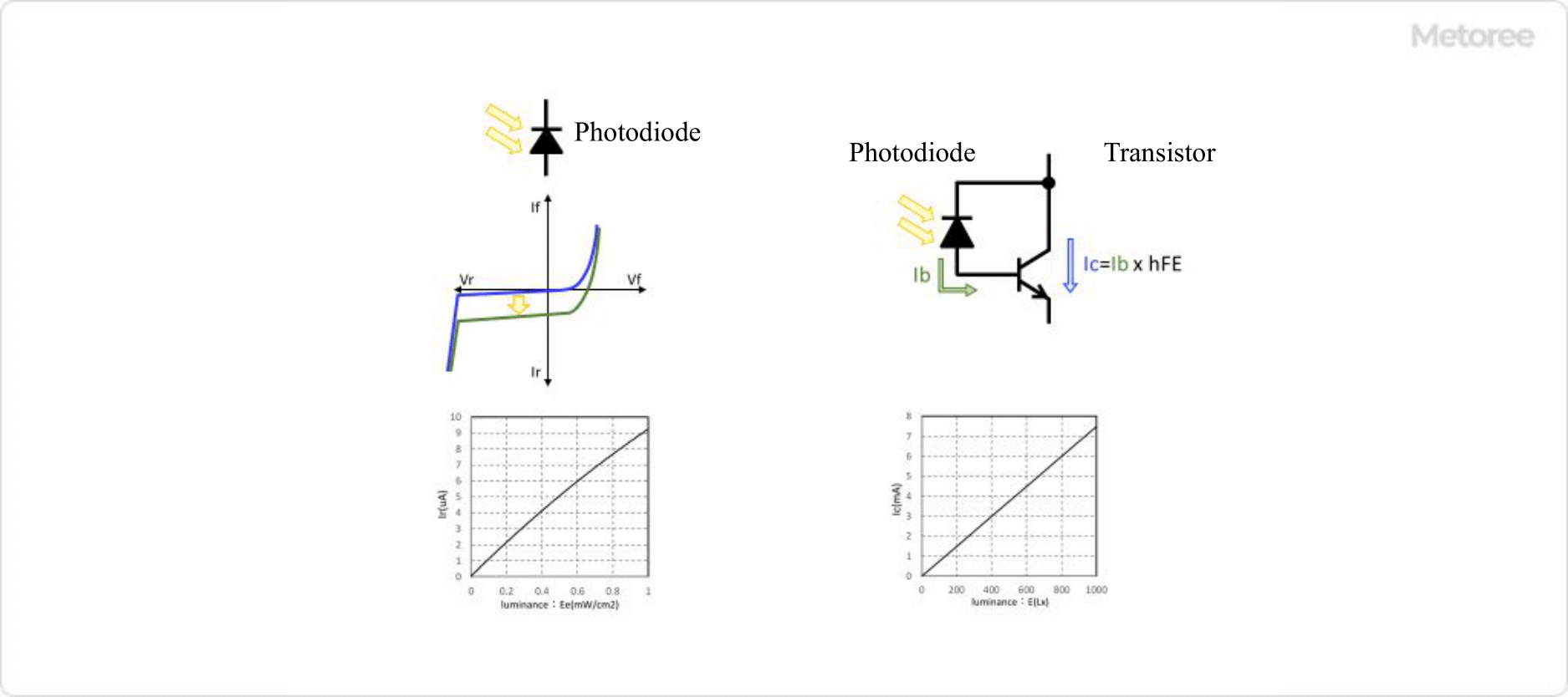
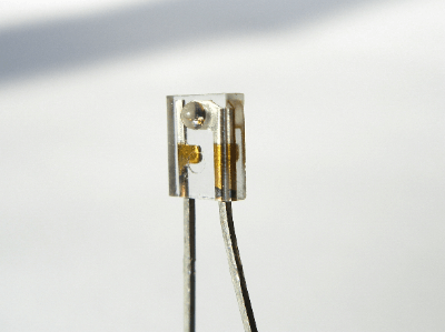
A phototransistor is a semiconductor device used to detect light.

Its structure is a combination of a phototransistor and a photodiode. Since they are available in a variety of shapes depending on the package, they must be selected appropriately for each application.

Uses of Phototransistors

236_Phototransistors_フォトトランジスタ-1.png

Figure 1. Uses of phototransistors

Phototransistors are widely used as light-receiving sensors. In particular, since they have a peak sensitivity around 800 nm, they are generally used to receive infrared light.

Specific examples of phototransistor applications include “light intensity measurement,” “infrared remote control receivers,” “photoelectric sensor receivers,” and “optical communications.” In particular, they are often used in combination with infrared LEDs in remote controls for TVs and air conditioners.

One application of optical communication is the gigabit optical communication service provided by internet providers. The light receiving part of that communication uses high-speed phototransistors, which are ideal for communication.

Phototransistors are also sometimes used as sensors in automatic doors. Furthermore, since phototransistors generate electric current by detecting light, they are used as switches driven by light, and so on.

Structure of Phototransistors

236_Phototransistors_フォトトランジスタ-2.png

Figure 2. Structure of phototransistor

Phototransistors are semiconductor devices with an NPN structure. This NPN structure allows the phototransistor to produce a larger output signal than a photodiode.

The NPN structure of the phototransistor amplifies the output of the photodiode with a transistor. When light equivalent to the energy gap of the semiconductor enters the transistor, electrons in the valence band are excited to the conduction band.

This causes migration to the N layer, and holes move to the P layer. This transfer from the N layer to the P layer causes a forward bias at the junction, which results in a current flow. 

The transistor used in phototransistor is characterized by the fact that it does not have a base electrode. However, the photocurrent generated by light reception becomes the base current, and this base current is amplified by the collector.

Features of Phototransistors

The amplification of the base current is hFE (transistor amplification factor) times as large as that of other transistors. However, as a characteristic of phototransistors, even if the hFE is the same, there is a tendency to use a relatively large hFE.

This allows a large collector current to be drawn from the tiny photodiode signal, but it should be noted that current is always leaking at the collector-base junction, and this leakage current is also amplified.

In other words, phototransistors have a weak current flow even in a completely dark environment. This weak current that flows even in a dark environment is called dark current. The dark current generated by a phototransistor is an internal noise as a light sensor. However, it is possible to suppress this internal noise.

The dark current has the characteristic of increasing when the temperature is high and, conversely, decreasing when the temperature is low. Therefore, internal noise can be suppressed by cooling the device using this characteristic.

Other Information on Phototransistors

1. Phototransistor and Transistor

236_Phototransistors_フォトトランジスタ-3.png

Figure 3. Photodiode and transistor

The IV characteristic of a photodiode shifts downward in response to the intensity of light (blue line becomes green line) when it is exposed to light. This change in IV characteristic is the standard for measuring light intensity. However, since the output current is in the order of uA, the output as it is would complicate the circuitry in the subsequent stages.

By combining a phototransistor with a photodiode and a transistor, it is possible to amplify the photocurrent generated when light is received by the photodiode by a factor of hFE, the DC current amplification factor of the transistor. Therefore, the phototransistor is more sensitive than the photodiode, and the output current of the phototransistor is in the order of mA, thus simplifying the circuitry in the subsequent stages. 

Phototransistors are several hundred times more sensitive than photodiodes, and if even higher sensitivity is required, the use of a Darlington-connected phototransistor can provide several hundred times x several hundred times higher sensitivity. This makes it possible to detect brightness of several Lux. 

2. Difference Between a CDS and Phototransistors

A CDS is a photoresistor, also called a CDS cell or a photoconductive cell. That is, the resistance increases when the illuminance is low and decreases when the illuminance is high.

The advantages of CDS are that the minute sensitivity characteristic is close to that of human vision. The structure is simple; the sensitivity is high, and the price is low.

For example, they are used in illuminance meters, exposure meters for cameras, and brightness detectors for automatic flashing lights. However, cadmium sulfide, the main material used as an element in CDS, is an environmentally harmful substance. For this reason, the use of CDS has been decreasing in recent years.

Phototransistors, on the other hand, provide an output current proportional to illuminance. Another advantage of phototransistors is their high sensitivity because of their structure, which combines a photodiode and a transistor.

カテゴリー
category_usa

Optical Cable

What Is an Optical Cable?

Optical cables are hollow cables made of glass or plastic ; they are also called fiber-optic cables.

They provide a path for light to travel, which is how they transmit information.

Optical communication using optical fiber is less susceptible to noise than telecommunications using metal cables and thus has the advantage of providing stable, high-quality communication.

The drawback of using light for communication is attenuation, but efforts are being made to solve this problem through the structure of optical cables and amplification at relay points.

Uses of Optical Cables

Optical cables are used for high-speed communication on fixed lines of the internet.Different optical cables are used for such optical communication depending on the communication distance and speed.

Optical cables connecting a fixed line from a base station to a home require high-speed communication over long distances, so cables with a small inner diameter are used to communicate at a single wavelength, called single mode.

On the other hand, optical cables with a large inner diameter are used for short-distance ethernet through media converters for multimode communication using multiple wavelengths.

In addition to these information and communication technologies, optical cables are also used for lighting by drawing light from a light source.

Principle of Optical Cable

Light has the property of traveling in a straight line, but it is gradually attenuated by scattering.Therefore, optical cables are designed to minimize light scattering.

Transmission of light using optical cables is performed by repeated total reflection of light inside the fiber.Total reflection means that, when light enters a medium with a large refractive index into a medium with a small refractive index, if the angle of incidence is larger than the refractive angle, all the light is reflected and none is transmitted through the medium.

Optical cables have a double structure called a cladding and a core, and light comes through the core.

The core is designed to have a higher refractive index than the cladding, so the incident light is repeatedly reflected and travels through the core in a confined manner.

However, if the cable is bent in the middle, the angle of incidence increases, resulting in light loss.Therefore, as the distance increases, the risk of such light loss increases.Optical amplifiers are used to amplify the attenuated light again to improve this situation.

Types of Optical Cables

There are two types of optical cables: single-mode fiber (SMF) and multimode fiber (MMF).

1. Single-Mode Fiber

Single-mode fiber cables are characterized by a narrowly designed range over which light can pass, resulting in a single mode of light transmission and reduced attenuation. Therefore, transmission over long distances and at high speeds is possible. Although it has high performance, it is expensive, so it is generally used for communication between facilities. 

2. Multimode Fiber

Multimode fiber cables are designed to have a large range of light transmission, and since light is transmitted in multiple modes, data loss is likely to occur due to the dispersion of light among each other. Therefore, it is suitable for short-distance communications and is used for laying lines within a facility. This makes them inexpensive.

Optical cables are divided into LC connectors, SC connectors, FC connectors, etc., depending on the shape of the connector. SC connectors are the most common type of connector. FC connectors use a screw-tightening method for connection and are characterized by their high cable fixing force.

カテゴリー
category_usa

X-ray Inspection System

What Is an X-ray Inspection System?

X ray Inspection System
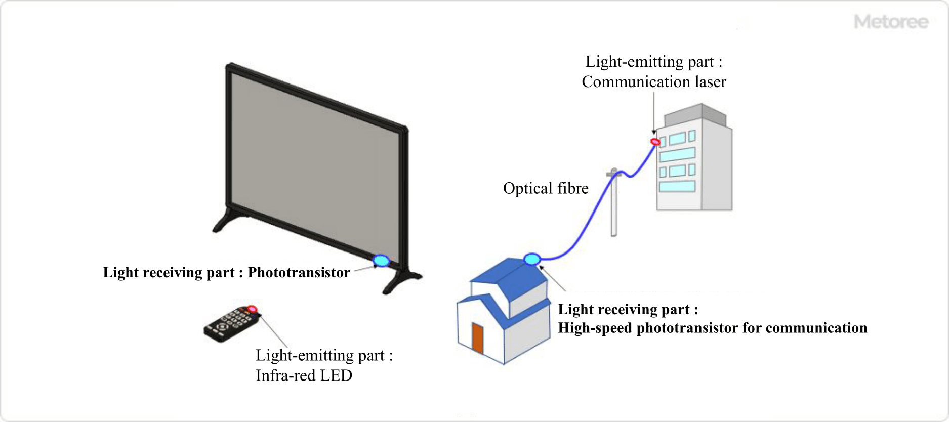
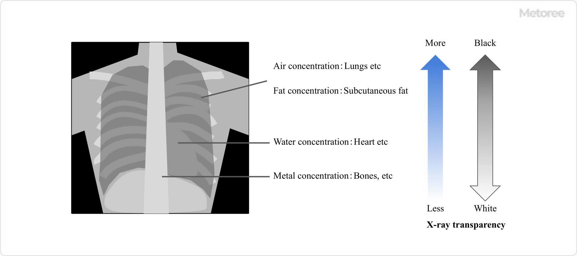
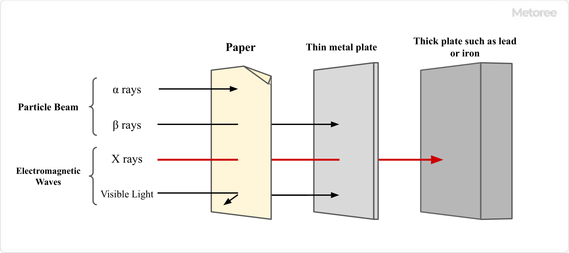
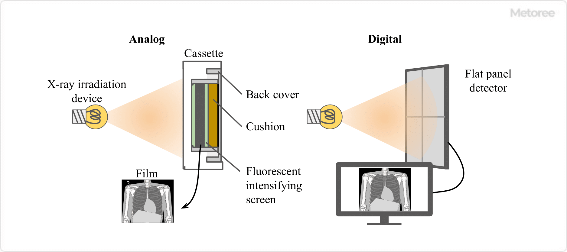
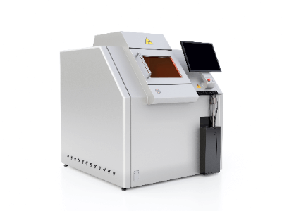
X-ray inspection equipment are devices that can accurately  identify elements and hazardous substances in areas invisible to the eye without destroying the object.

Based on the transmitted image obtained by irradiating X-rays to the inspected item, the invisible internal conditions are inspected and evaluated.

Since it can see through the inside of a product, which cannot be photographed by a visible light camera, this equipment is indispensable for maintaining high quality in manufacturing, including measures to prevent contamination by foreign matter and hazardous substances.


Applications of X-ray Inspection Systems

Today, X-ray inspection systems are used not only in the manufacturing and processing of medical, food, and electronic parts, but also in the construction and aviation industries.

Examples include X-ray imaging at hospitals and baggage checks at airports.

In the medical industry, they are used for endoscopes, CT scanner systems, digital ray systems, and in research fields such as animal research.

Principle of X-ray Inspection Systems

_X-ray-Inspection-System_X線検査装置-1

X-rays are a form of radiation consisting of photons that have high energy and propagate in flux, and “electromagnetic rays” with short wavelengths. X-rays are a type of radiation.

There are five types of ionizing radiation, including X-rays: alpha rays, beta rays, gamma rays, X-rays, and neutron rays.

Among these, X-rays, along with gamma rays, are electromagnetic waves with very short wavelengths, making them highly penetrating through matter by passing between atoms that make up matter.

However, they can be blocked by thick plates of lead or iron.

When X-rays collide with electrons orbiting the nucleus of a material, various interactions such as the photoelectric effect and inelastic scattering occur.

X-rays that do not undergo these phenomena penetrate the material and become transmitted X-rays, and the more transmission there is, the darker the image appears.

Conversely, areas that are attenuated appear bright and white. In fact, images taken using X-rays are black and white, where the shade is determined by the amount of transmitted X-rays.

In general, it is known that the intensity of transmitted X-rays is determined by factors such as the atomic number, density, and thickness of the object material.

Miniaturization of X-ray Inspection Equipment

X-rays, discovered by Roentgen in 1895, are electromagnetic waves with wavelengths of approximately 1 pm – 10 nm.
They are also a form of radiation, and are used in X-ray photography for medical examinations and nondestructive testing, as well as in the analysis of crystal structures using the diffraction phenomenon.
Most people’s conception of X-ray inspection equipment is that it is a large-scale device that takes pictures of the entire body.
However, today, a wide variety of portable X-ray inspection systems are available, and they are mainly used for nondestructive testing at factories and construction sites.

Their features are often referred to as portable nondestructive testing equipment that can be easily used at any time and place.
It is a device that inspects all kinds of objects with X-ray images by combining a polarized X-ray and a high-precision digital detector.
Without destroying the object to be inspected, it is possible to check for cracks, fissures, corrosion, and other abnormalities, as well as the finish of welded parts.
X-ray inspection systems are highly mobile and ideal for completion and periodic inspections at factories and construction sites. However, since they are a source of ionizing radiation, they should be handled with care.

Instrumentation Amplifier

What Is an Instrumentation Amplifier?

An instrumentation amplifier is designed to accurately amplify very weak signals from various sensors, such as strain gauges and pressure transducers, with high precision. These amplifiers are essential in manufacturing equipment and facilities for measuring pressure and temperature, thanks to their circuits optimized for amplifying sensor signals.

Unlike common operational amplifiers, instrumentation amplifiers offer more precise gain settings within a narrow, predefined range, significantly enhancing measurement accuracy.

Uses of Instrumentation Amplifiers

Instrumentation amplifiers are pivotal in industrial instrumentation, motor control, in-vehicle equipment, and data acquisition systems. They excel at detecting and amplifying weak sensor signals with minimal noise, optimizing sensor performance across various applications.

Principle of Instrumentation Amplifiers

Featuring differential inputs and single-ended outputs, instrumentation amplifiers excel at suppressing input noise and boast a high common-mode rejection ratio (CMRR). They maintain high input impedance, typically several hundred MΩ, by balancing differential inputs, while keeping output impedance low to ensure precise measurements. The amplifiers’ gain is usually set through resistors within a narrow, predefined range, limiting flexibility but allowing for exceptional accuracy.

Other Information on Instrumentation Amplifiers

1. The Difference Between an Operational Amplifier and an Instrumentation Amplifier

Though both types of amplifiers incorporate operational amplifiers in their designs, their applications and circuitry significantly differ. Operational amplifiers are versatile, used in a wide array of analog circuits with an external feedback loop influencing their characteristics. Instrumentation amplifiers, on the other hand, lack this external feedback loop, focusing instead on differential amplification and common mode rejection, making them ideal for handling weak sensor signals.

2. Integration Into Sensor ASICs

While some instrumentation amplifiers exist as discrete components, they are often integrated into ASIC circuits with Wheatstone bridge circuits for pressure transducers and other sensors. This integration facilitates monolithic ICs, improving amplifier characteristics, and allows for sensor parameter compensation, including temperature, alongside digital interface integration for microcontrollers. This makes them well-suited for compact and high-value applications.