カテゴリー
category_usa

Arrester

What Is an Arrester?
Arresters

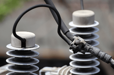
An arrester is a lightning arrester that prevents damage to equipment caused by lightning and other lightning events.

When lightning strikes directly, large currents and voltages explode in the vicinity. These are called lightning surges, and they have a variety of adverse effects on electrical equipment. There is also the danger of destroying not only power transmission and distribution equipment but also electricity demand facilities through power lines.

The purpose of installing arresters is to discharge these lightning surges and protect electrical equipment from lightning.

Uses of Arresters

Arresters are used to protect electrical equipment from lightning surges generated by lightning. Specific uses of arresters are as follows:

  • Inside of power receiving and distribution panels at power plants and substations
  • Inside large DC current-carrying equipment for electrolysis
  • Mid-belly of overhead instrumentation wiring
  • Mid-belly of overhead telephone lines
  • Mid-belly of low-voltage power lines

There are two types of arresters, one for signal wiring protection and the other for power transmission and distribution line protection, each of which differs in size and scale. In addition, outdoor electrical facilities are more likely to be affected by lightning strikes and are generally protected by arresters.

Principle of Arresters

Arresters are broadly classified into two categories according to the discharge method: gapped arresters and gapless arresters for discharging.

1. Arrester With Gap

An arrester with a gap is an arrester in which a gap exists between the wire and the grounding pole. Normally, the gap is insulated by the nature of the gap, but when an abnormally high voltage such as lightning occurs, the insulation of the gap is destroyed and discharges a current to the earth. However, the insulation may be destroyed if the device is struck by lightning more than once at a time. Another disadvantage is that it is difficult to miniaturize.

2. Gapless Arrester

A gapless arrester is an arrester in which no gap exists. Instead, elements such as zinc oxide are used. They are characterized by their current-voltage characteristics that are ideal for lightning protection, minimizing the current flowing to the ground during steady-state operation. This type of arrester is currently the mainstream.

Other Information About the Arresters

1. Classification of Arresters

Depending on their purpose, arresters can be divided into two categories: those for power supply and those for communication. When used for power supply, they can be classified from Class I to Class III.

  • Class I: Electric power draw board
  • Class II: In distribution boards and control panels
  • Class III: Near electrical and electronic equipment

For telecommunications, the categories are subdivided as A1, A2, B1, B2, B3, C1, C2, C3, D1, and D2.

2. Installation Criteria for Arresters

According to the technical standards for electrical equipment, arresters are to be installed in customers with power contracts of 500 kW or more; if a device with a built-in arrester, such as PAS (air-load switchgear) or UGS (underground line load switchgear), is selected, it can be used as an alternative.

Since the purpose of installing arresters is to protect electrical and electronic equipment from lightning surge voltages, it is important that they discharge quickly to the ground when a surge occurs. Therefore, it is necessary to consider the installation location and grounding resistance of the arrester. As for the installation location, it is desirable to install at a location where lightning surges can easily penetrate, so it is generally recommended to install at the power receiving point.

In addition, to suppress abnormal voltage, reducing the grounding resistance of surge arresters is effective. When the grounding pole is class A, the grounding resistance is specified to be 10 Ω or less, but an even lower resistance will have a great effect. To suppress grounding resistance, there are several methods, such as increasing the wire thickness or shortening the laying distance of the grounding wire. Increasing or enlarging the size of buried metal is also effective.

A similar term is lightning rod, but care should be taken not to confuse the two. Lightning rods also have standards for installation, so it is necessary to check building codes and other regulations before installation.

3. History of the Arrester

Until the 1960s, gapped arresters were the mainstream. However, gapped arresters were prone to ground fault accidents due to fouling of the gapped area. In addition, it was difficult to reduce the size and weight of the gapped arresters in order to secure the gap.

In the 1970s, a Japanese manufacturer developed a gapless arrester using zinc oxide. Because of their compact size, light weight, and high reliability, gapless arresters using ZnO are now the mainstream type of arresters.
カテゴリー
category_usa

Air Tank

What Is an Air Tank?

Air Tanks

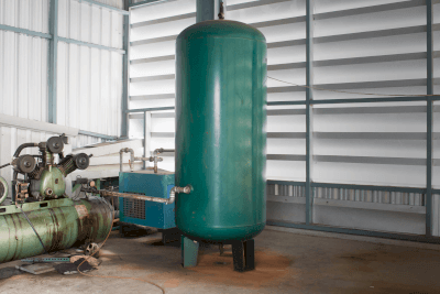
An air tank is a pressure-resistant container for storing air pumped by an air compressor. It is an important device that contributes to a stable supply of compressed air and to extending the service life of the air compressor.

Even if the air compressor should break down, the compressed air remaining in the tank allows work to continue to some extent.

There is a wide variety of products available, from portable to large stationary models, and you can select the appropriate product according to the capacity of your air compressor.

Uses of Air Tanks

The air compressor stores air pumped by the air compressor and supplies compressed air to power various air tools, full-pneumatic brakes and air suspensions of large vehicles, shift cylinders, and other equipment.

Portable air tools can be used on the road by filling them with compressed air in advance using an air compressor.

Those used in large vehicles are equipped with a pressure gauge that alerts the driver with sound and display when air pressure drops due to excessive braking or other factors.

Principle of Air Tanks

Since compressed air can be stored, the service life of air compressors can be extended and the frequency of maintenance is reduced.

In addition, since the stored compressed air is reduced to a constant pressure via a regulator and then pumped into each pipe, pressure fluctuations originating from the air compressor are unlikely to occur.

In addition, since water accumulates at the bottom of the pressure-resistant container due to internal condensation caused by repeated depressurization and pressurization, a drain valve is provided at the bottom of the main unit. If the tank is left unattended without draining, internal corrosion may occur, causing air leaks or, in the worst case, the pressure-resistant container may explode.

Each air tank has a pre-defined amount of compressed air to be filled, but if the tank is not selected according to the rated output of the air compressor to be used and its capacity to boost the pressure, the supply may not keep up with the demand, which may shorten the life of the air compressor.

カテゴリー
category_usa

Adhesives for Urethane

What Are Adhesives for Urethane?

Adhesives for urethane are suitable for bonding urethane rubber used for shoe soles and urethane foam, often used for sound absorption and thermal insulation.

Although the name “adhesives for urethane” is not often used, silicone resin adhesives and urethane adhesives are used to bond urethane rubber such as shoe soles. SBR (styrene-butadiene rubber) adhesives and chloroprene rubber solvent-based adhesives are also used for bonding urethane foam.

Uses of Adhesives for Urethanes

Adhesives for urethane are used to bond urethane rubber, urethane foam, and other materials. Urethane rubber is used in a very wide range of fields, including familiar shoe soles, casters, industrial rollers, shock absorbers, and forklift tires.

Adhesives for urethane suitable for urethane rubber are used as needed during the manufacture or repair of these products. The fields in which urethane foam is used are also very wide, including building materials such as sound absorbers and heat insulators, as well as cushioning materials such as bedding and household products such as kitchen cleaners.

Adhesives for urethane foam are also used as needed in the manufacture and repair of these products, as well as in the adhesive process during construction.

Features of Adhesives for Urethane

Adhesives for urethane include modified silicone resin adhesives and silylated urethane resin adhesives suitable for urethane rubber, SBR adhesives suitable for urethane foam, and chloroprene rubber solvent adhesives.

1. Modified Silicone Resin Adhesive

Modified silicone resin adhesives are reaction curing type adhesives that are mainly composed of modified silicone polymers and are cured by moisture in the air and catalysts. In addition to bonding urethane rubber, they are often used as sealants.

Most modified silicone adhesives suitable for bonding urethane rubber are one-component types, but two-component types are also available. One-component types cure through a condensation reaction with moisture in the air, which generates alcohol and other by-products during curing, while two-component types cure through an addition reaction, which generates no by-products.

2. Silylated Urethane Resin-Based Adhesive

Silylated urethane resin-based adhesives are typical among urethane resin-based adhesives and reacts to moisture in the air or on the bonding surface to cure. In addition to having strong adhesive strength, they are highly shock absorbent as they become elastic and rubbery after curing. Silylated urethane resin-based adhesives have high water and heat resistance and are used as sealants for indoor, outdoor, uneven surfaces, and around water.

3. SBR-Based Adhesives, Chloroprene Rubber Solvent-Based Adhesives

The main component is a polymer elastomer such as SBR (styrene-butadiene rubber) and chloroprene rubber, which is an adhesive dissolved in an organic solvent.

Other Information on Adhesives for Urethane

1. When Bonding Urethane to Metal

Urethane adhesives and modified silicone adhesives are suitable for bonding urethane resins and metals. Since these adhesives are suited for bonding rubber and materials of different materials, they are also very effective for bonding urethane resins and metals.

There are three tips for using adhesives in this way: first, clean the metal or rubber surface so that it will not repel the adhesive; second, apply the adhesive thinly and evenly to eliminate unevenness in application. The third tip is to allow the adhesive to stand still long enough after bonding to harden. The above tips will improve the adhesive strength.

2. General Urethane Adhesives

Common urethane adhesives come in one-component and two-component mixed types. Urethane adhesives are more flexible and impact-resistant than other reactive adhesives, such as epoxies and acrylics.

They cannot be wiped off after curing, so wiping should be done quickly before curing. In addition, it is recommended to ventilate well and wear safety glasses, masks, and gloves, as it may cause irritation to the eyes and nose during use.

Among urethane adhesives, one-component types are relatively weak in strength, while two-component types tend to have stronger adhesion, longer life, and higher heat and weather resistance. For this reason, the two-component type can be used in a wider range of locations.

カテゴリー
category_usa

Dust Collector

What Is a Dust Collector?

Dust Collectors

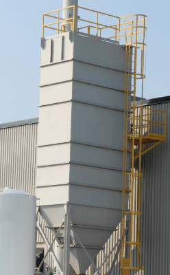
Dust collectors are machines designed to remove dust and sediment from various environments. Used in settings such as sewage and drainage facilities, these devices use rake or rotating net methods to efficiently capture and eliminate debris. The choice between a rake-style and a rotating net-style dust collector depends on the specific needs and location of use.

Applications

Dust collectors play a vital role in keeping rivers, streams, and other water bodies clean by removing debris and stagnant materials. They are instrumental in drainage facilities, allowing water to flow naturally while removing unwanted materials. These devices find utility in diverse settings, including agricultural lands, industrial sites, water treatment facilities, and power plants, among others. Enhanced by conveyor belts and suction mechanisms, dust collectors can efficiently transport waste, offering customization through additional features to meet various operational requirements.

Operating Principles

Dust collectors feature a cylindrical roller, known as a rake, fitted with needles that break down and collect debris. Some models feature multiple rakes attached to a chain for continuous operation, allowing for the efficient collection of large amounts of refuse. Dust collectors can also be equipped with screens or nets of varying mesh sizes, adaptable to the type and size of debris being targeted, ensuring comprehensive removal.

Types

Dust collectors come in several forms, including rotary and reciprocating rake styles, with options for stationary or mobile operation. Net dust collectors, available only in rotary models, can be aligned parallel or perpendicular to the channel axis, with dual-flow and straight-flow configurations offering different water flow directions. These devices are further divided into separate and endless net styles, catering to specific debris removal needs.

Selection Criteria

When selecting a dust collector, considerations include the rake’s movement direction and the device’s compatibility with existing infrastructure. Rake collectors vary in their debris collection methods, with some optimized for small debris and others capable of handling larger objects. The choice often depends on the existing screen setup and the size of debris common to the site.

Design Considerations

The construction of dust collectors involves considerations for screen width, material composition, and environmental exposure. Materials like SS400 steel are common, with special coatings applied for parts submerged underwater or exposed outdoors. Stainless steel options are favored for their durability and extended service life. Manufacturing processes include welding and machining, with specific requirements for paint type and thickness to ensure longevity and performance.

カテゴリー
category_usa

Crossed Roller Ring

What Is a Crossed Roller Ring?

Crossed roller rings are bearing components that can support loads in various directions simultaneously, such as radial, axial, and moment loads.

It is ring-shaped in appearance. Multiple cylindrical rollers are arranged in series alternately in the ring through spacer retainers on the 90° V-groove shaped rolling surfaces, so that loads from various directions can be supported.

Uses of Crossed Roller Rings

Crossed roller rings are used in many industrial machines. The range of uses is wide, including joints and swivel sections of industrial robots, swivel tables of machining centers, manipulator swivel sections, precision rotary tables, medical equipment, measuring instruments, and IC manufacturing equipment, to name a few. The wide range of uses of our products can be attributed to the following advantages:

  • Excellent Rotation System
    Prevents roller skew and increases rotational torque due to mutual friction between rollers.
  • Stable Rotational Torque
    Stable rotational torque can be obtained even when pressurization is applied, resulting in high support rigidity and highly accurate rotational motion.
  • Easy to Handle

Principle of Crossed Roller Rings

Crossed roller rings can support loads in various directions because the rollers are arranged alternately at a 90° angle. Since rollers are used as rolling elements, large loads can be supported.

Also, since the rollers are arranged in alternating rows perpendicular to each other, the cross rollers can support loads from various angles.

Types of Crossed Roller Rings

There are six main types of crossed roller rings:

1. RU Type

Since the RU type has a seated structure with integral inner and outer rings, there is virtually no effect on performance due to assembly, and the rotational accuracy and torque are stable. The RU type is also characterized by the fact that it does not require a flange housing.

2. RB Type

The RB type is the basic form of crossed roller rings, in which the outer ring is divided into two parts and the inner ring is a single piece. It is characterized by the fact that it is used where rotational precision is required in the inner ring.

3. RE Type

The RE type has the same dimensions as the RB type, but this type is used where the rotational accuracy of the outer ring is required.

4. RB/RE Type-USP Series

The RB/RE type-USP series exceeds the world’s highest accuracy standards and is a top class in precision.

5. RA Type

The RA shape has the thinnest possible thickness of the inner and outer rings of the RB shape.

6. Type RA-C

The RA-C type has the same dimensions as the RA type, but can also be used for outer ring rotation. The RA-C type has a one-part split outer ring structure and features high rigidity, even for the outer ring.

Other Information About Crossed Roller Rings

1. Installation of Crossed Roller Rings

The wall thickness of the housing in which the crossed roller rings are mounted must be determined in consideration of the rigidity of the part. Insufficient strength will cause deformation of the bearing and uneven roller contact inside, leading to premature breakage and deterioration of rotational accuracy.

The wall thickness of the housing should be designed to be at least 60% of the cross-sectional height of the crossed roller ring. In addition, if a tapped hole is drilled for removal, the crossed roller ring can be removed without putting a load on it, preventing damage at the time of removal.

When installing the push flange to secure the crossed roller ring, the order in which the bolts are tightened is also important. In order to tighten the bearings evenly, it is important to tighten the diagonal screws little by little and assemble them so that the tightening is uniform.

Thus, when using a high-precision rotating mechanism, it is necessary to pay attention not only to the machining accuracy of the crossed roller rings but also to the machining accuracy of the mounting parts and the assembly method.

2. Pressurized Crossed Roller Rings

Crossed roller rings can be pressurized in the same way as ordinary ball bearings. Applying pressurization increases the support of rigidity and rotational accuracy. On the other hand, since rotational friction increases, care must be taken when calculating rotational power.

Pressure is usually applied by setting the radial clearance to a negative value. The recommended dimensional tolerance of the housing and shaft to which the crossed roller ring with applied pressure is attached is g5/H7, and the fit must be set so that the ring does not clamp. If the fit is tightened, the internal stress will be high due to excessive pressure, which may cause breakage.

カテゴリー
category_usa

Flat Hinge

What Is a Flat Hinge?

Butt Hinges

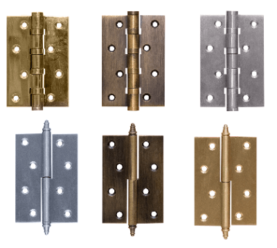
Flat hinges are common fittings used to connect two types of objects, such as a swinging door, lid, or gate, by supporting them by an axis to open and close them.

A hinge is a component that usually has limited moving parts and consists of two wings mechanically connected by a core rod or other means. Because they are attached to objects that open and close, such as doors, it is necessary to select flat hinges that are appropriate for the location where they will be used and where they are attached.

Flat hinges are the best size hinges for tight spaces and frames. The pins are secured to the wings of the frame, allowing the door to be lifted quickly off the hinges without removing the pins. Some flat hinges have multiple screw holes in the wings for mounting to the door frame.

Uses of Flat Hinges

Various types of hinges have been developed. Major hinges include long hinges, extractor hinges, flag hinges, spring hinges (spring hinges), slide hinges, free hinges (double opening), release hinges, torque hinges, clean hinges, auto hinge hinges, square hinges, cabinet hinges, hidden hinges, and glass hinges.

They are mainly used for opening and closing doors, pianos, study desk drawers, cabinets, and storage shelves. Each hinge has different characteristics and uses of its own, and if not used in the right place, the hinge may break.

Principle of Flat Hinges

A hinge consists of two plates or wings, joined by a free-running pin for both plates to rotate.

The plates of a normal hinge have holes in them for attachment to doors or other moving parts. The holes can be self-tapping, machine screwed, nuts, bolts, or rivets.

Structure of Flat Hinges

The names of the hinge components are as follows:

1. Feather

It is the flat part of the hinge that extends horizontally and is screwed into the door. Depending on the number of tubes into which the pin (core rod) is inserted, it is called a two-tube wing or a three-tube wing.

2. Knuckle

The pin passes through the middle (circular) part of the hinge where the wings meet.

3. Barrel

The row of knuckles is called the barrel.

4. Pin (Core Rod)

It is the long section that slides into the knuckle and holds the two wings together.

5. Wood Screw Holes

These are screw holes for fixing the wings to doors, etc. Each feather has two or three holes.

6. Nylon Ring

To reduce friction, ball bearings may be inserted into the pipe joint.

Types of Flat Hinges

Hinges come in a wide variety of sizes, features, and materials. Flat hinges are the most commonly used hinges in all settings. When we refer to hinges, we generally mean flat hinges.

Long hinges are longer than flat hinges and are used for long doors, such as piano keyboard lids. Flag hinges have two separate hinges, one on the mounting side and the other on the door side, and the hinges can rotate 360° around an axis. Spring hinges are used in countertops and other applications where the door closes automatically. Free hinges also have a spring inside and can be used on bar counters.

Hinges often used in kitchen doors and furniture are angle hinges and slide hinges. Torque hinges generate resistance when opening and closing, so they can be maintained at any angle. Auto hinges can control the speed of opening and closing, and concealed hinges are hinges that are not visible when the door is closed. In addition to hinges commonly used for sideboards and cabinets, there are also special hinges for acrylic and glass doors.

How to Choose a Flat Hinge

Flat hinges are suitable for attaching to small windows or small boxes. They are suitable for lightweight materials and are often seen in DIY projects. They are easy to install, and stylish or antique-style flat hinges are also available. Flat hinges are available in a variety of colors, including bronze and gold.

Place flat hinges temporarily before installing. If the flat hinge moves during the work, it must be lightly secured with masking tape. Basically, two flat hinges are used, and three are used for doors that are more than 2 m long. Before drilling the holes, mark the centre of the screw hole. Fasten the screws to the drilled holes and be careful not to over-tighten them.

カテゴリー
category_usa

Shim Tape

What Is Shim Tape?

Shim Tapes

Shim tape is a thin metal tape widely used to adjust the position and fine-tune the height of equipment by inserting it between the gaps.

Shim means “filler.” For example, when each part is assembled, each part is within tolerance, but when the parts are assembled, the overall position may not fit together due to accumulated tolerances.

In such cases, fine adjustment of the thickness of the parts that do not match can be done with a shim tape to align the parts. Also, when the plane of a component set in a device is tilted, the tilted plane can be fine-tuned by inserting a shim tape of the required thickness.

Uses of Shim Tapes

Shim tape is often used for height adjustment in dies and for positioning workpieces on machine tools. In the case of height adjustment in dies, fine adjustment of height is made by inserting shim tape equivalent to the thickness of the adjustment amount between the mounting surfaces of each plate when they are combined, thereby improving machining accuracy.

In the case of a machine tool, the shim tape compensates for the inclination of the mounting surface for machining the workpiece (= workpiece to be machined) and enables parallelization. With the use of shim tape, machining of the workpiece with a uniform flat surface can be expected.

It can also be used to compensate for tilting and gaps in equipment, thereby reducing rattling and noise during operation caused by gaps.

Principle of Shim Tapes

The principle of shim tape is not to be used as a tape for bonding objects together, but rather as a thin metallic tape that can be cut to any length and inserted into the desired adjustment point as an individual piece of thin metal plate. By inserting the cut tape at the desired location, it is possible to adjust the machine, mold, or flat surface before machining.

The length (height) of the gap can also be measured by inserting the shim tape into the gap. Before machining a workpiece, the workpiece is set up. If the plane consisting of the table and the workpiece is tilted, the hole will be tilted when machining a hole.

To adjust the plane, shim tape is placed between the table and the workpiece on the side of the workpiece that is less flat, the plane is measured again to check the inclination, and if there is no problem, machining is performed.

Other Information About Shim Tape

1. Examples of Shim Tape Specifications

Various specifications of shim tape are available.

Material of Shim Tape

Usually these two types are used, but brass is sometimes used by some processors.

Shim Tape Standards
General shim tape thicknesses range from 0.005 mm to 2.0 mm, allowing the use of a thickness that best suits the purpose. Also, the standard tape width is 12.7 mm (special widths are also available), and tape lengths of 1 m and longer can be purchased.

2. Difference Between Shims, Liners and Spacers

The terms “shim” and “liner” are used for similar purposes, and there is really no clear definition. In some cases, however, shims are often used for thinner materials and liners for thicker materials, with shims being used for materials less than 1 mm and liners for materials greater than 1 mm.

The main use of both is as fillers to replenish gaps. Spacers, on the other hand, are plate-shaped fillers with a slightly different meaning. Spacers, on the other hand, are board-shaped fillers with a slightly different meaning: they are used to fill gaps. In other words, the height and position adjustment purposes are the same as for shims and liners, but spacers are often not used for tilt adjustment purposes.

3. Precautions When Using Shim Tape

Shim tape is often used for height and position adjustment purposes, but too much use of this tape may result in the inability to reproduce the same condition. It is difficult to exceed the target height and tilt accuracy of the original machine tool or mold in terms of process capability, and if the shim tape used is lost or misplaced when the equipment is disassembled, there is a risk that the original condition cannot be restored.

It is important to consider the target accuracy of molds, machine tools, and assembled parts carefully, and where the adjustment allowance is to be made before use.

カテゴリー
category_usa

Rubber Seal

What Is a Rubber Seal?

A rubber seal is a sealing material made of rubber, which is used in a wide range of fields, such as packing, gaskets, and oil seals, taking advantage of the properties of rubber.

In fields where airtightness is required, cushioning properties are required. On the other hand, if the main purpose is to prevent liquid leakage, materials with high strength and excellent durability are used in most cases.

In addition, rubber seals are made of the most suitable rubber material for each application. For example, for outdoor use, rubber with good environmental resistance is used.

Uses of Rubber Seals

Most rubber seals are made of nitrile rubber (NBR), which has a good balance of various properties, and are widely used for oil seals for automobiles, O-rings, heat-resistant hoses, belts, and other applications. Since many varieties are manufactured for different applications, they are selected from a wide range of products and adopted.

In addition, rubber seals made of silicone rubber are often used in connector gaskets for electrical components and waterproof gaskets for automobiles because of their excellent resistance to heat, cold, lubricating oil, and water.

Properties of Rubber Seals

Rubber seals consist of various types of rubber, a material that fills gaps between solid substances. The elasticity of the rubber allows it to adhere to the gap and prevent distribution between them.

The fluids that can be stopped by rubber seals are gases or liquids. Among them, they are most often used to seal water or oil.

Rubber seals are available in a variety of forms, including pre-molded rubber that is pressed into the gap, as well as liquid rubber that is injected into the gap and allowed to solidify. Filled rubber seals are often used in applications where small gaps are not allowed and where removal is not a prerequisite. For example, filled rubber seals are ideal for waterproofing uses of building materials used in construction.

Types of Rubber Seals

The most commonly used types of rubber seals are called “gaskets,” “packings,” and “O-rings.”

1. Gasket

Gaskets are seals for fixing. They are used to seal connections in parts and piping. Gaskets are placed between connections and secured with bolts, etc. to seal gaps between connections and prevent leakage of fluids passing through the interior and contamination by foreign matter.

Selecting the gasket material according to the operating environment and fluid prevents leakage and gasket deterioration.

2. Packing

Packing is a sealing material for motion. Packing is used to seal parts that are repeatedly put on and taken off, or that rotate or reciprocate.

Among packings, those that come in contact with parts in particular motion are called contact seals. Oil seals for mechanical parts and gland packings for pumps are contact seals.

3. O-Ring

O-rings are used primarily for installation in grooves of parts and other components. It can be a gasket or a packing. It is circular and has a self-sealing action that uses pressure, such as atmospheric or hydraulic pressure, to seal fluids. It is widely used in applications ranging from common water faucets to stainless steel pressure vessels.

カテゴリー
category_usa

Pushbutton Switch

What Is a Pushbutton Switch?

Pushbutton Switches

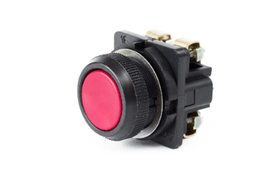
A pushbutton switch is a switch that opens and closes electrical contacts by human operation.

It refers to a component whose contacts are changed to open or close when a person pushes it in with a finger.

Uses of Pushbutton Switches

Pushbutton switches are used in a wide range of applications, from daily necessities to industrial machinery, and are often seen in our daily lives. Specific uses of pushbutton switches are as follows:

Principle of Pushbutton Switches

Pushbutton switches consist of a button, case, and contacts.

1. Button

The button is the part that a person pushes in. Generally, colored resin materials are used to insulate the button from the electric circuit and to color-code the function of the button.

2. Case

The case is the exterior part that holds the pushbutton and electrical circuits. It supports the internal mechanism while protecting it from the outside and prevents people from easily touching the electric circuits. Therefore, it is composed of insulating materials such as resin or rubber.

3. Contact Point

The contact is the part that converts the operation on the pushbutton into an electrical contact. It consists of a spring and a piece of metal. The spring restrains the button to return to its original position after being pushed. The metal strip consists of a fixed contact and a movable contact, etc., and conducts or breaks the electrical signal.

Types of Pushbutton Switches

There are two functional classifications of pushbutton switches: alternate and momentary.

The former is a switch that is activated only while the button is depressed and simultaneously deactivated the moment the finger is released. The latter is a switch that is activated when the button is pushed buttoned and continues to be activated thereafter until the button is pushed again.

1. Alternate Type

In pushbutton switches, alternating refers to a switch that alternates states each time it is pressed. Buttons for function selection, for example, should be of the alternate type because they should retain their state. The main power supply of a monitor or the power supply of a flashlight are examples.

2. Momentary Type

In pushbutton switches, momentary refers to a switch that is activated only while it is pressed. It is used when you want to make a delicate action, or when you want to press it only once for a single action. A video game controller is an example.

Various other types are also available and are selected according to the specifications of the equipment. In places where people frequently pass by, covered or guarded switches are often used to prevent accidental operation.

Pushbutton switches with lamps are also available, and the lamps can be lit by supplying power. They are called illuminated pushbutton switches. The “ON” and “OFF” states are indicated by the illumination of a lamp.

Other Information on Pushbutton Switches

1. How to Wire a Pushbutton Switch

Various types of wiring methods for pushbutton switches are sold by various manufacturers, but the most common types are soldering, screw terminals, and spring terminals. The soldering type connects the wiring to the terminals with solder. Generally, the connection part and the button part can be split, and only the button part can be replaced.

In the screw terminal type, the wiring is crimped to a crimp terminal such as a Y terminal or a round terminal, and fixed to the connection part of the pushbutton switch with a screw. The spring terminal type is fixed by clamping the wiring with a spring. Crimp terminals are not necessary and wiring work can be easily performed. However, there are cases where a rod terminal is used for the terminal section.

2. Contacts of a Pushbutton Switch

Pushbutton switches have three types of contacts: A, B, and C. The A-contact is the one that conducts when the button is pushed in. The A-contact is the contact that conducts when the button is pressed in. Normally, the switch is open and no current flows through the circuit. It is also called a normally open (NO) contact, meaning that it is normally released.

The B contact is the contact that opens when the button is pushed in. In normal operation, the switch is in a conducting state and current flows through the open circuit. It is also called a normally closed (NC) contact. (NC) Also called a contact.

A c-contact is a three-terminal contact that combines an A-contact and a B-contact. A-terminal, B-terminal, and A-common terminal. In normal operation, the A-terminal is open and the B and common terminals are conducting. When the switch is pushed in, the A-terminal and the common terminal conduct and the B terminal is open.

カテゴリー
category_usa

High-Side Switch

What Is a High-Side Switch?

A high-side switch is a semiconductor device that turns the power supply on and off for loads such as motors, solenoids, inductors, and LEDs.

In most cases, P-channel MOSFETs are used as semiconductors. In the circuit wiring, the switch is placed on the power supply side of the load, so it is called a high-side switch.

When the high-side switch is ON, power is supplied to the load, and when the high-side switch is OFF, power is not supplied to the load. When the switch is placed on the output side of the load (opposite side of the power supply) in the circuit wiring, it is called a low-side switch.

Uses of High-Side Switches

High-side switches are used to supply or disconnect power to a variety of loads. Specifically, they are often used in inverters, power on/off circuits, LED drivers, and inductance load drivers such as motors and solenoids.

Since large currents are often applied to the load, it is necessary to design the inrush current countermeasures and reverse current prevention circuits into consideration. Because the power supply to the load is turned on and off by a semiconductor device, rather than a mechanical switch such as a relay, the ON/OFF speed can be increased.

If you want to control the output of the load ON/OFF while the power supply to the load remains ON, use a low-side switch.

Principle of High-Side Switches

There are two types of FETs: P-channel type and N-channel type. When FETs are used as low-side switches, N-channel type FETs are often used. When used as a high-side switch, P-channel FETs are generally used.

When a negative gate-source voltage is applied to a P-channel FET, the resistance between the drain-source decreases and current flows from the source to the drain. The power supply and load must be connected to the FET according to the direction of the current flow, so connect the power supply to the source of the P-channel FET and the load to the drain.

A P-channel FET functions as a high-side switch because current flows from the source to the drain when the gate voltage is lower than the supply voltage connected to the source.

Other Information on High-Side Switches

1. Principle of Fet

While transistors are called “base,” “emitter,” and “collector,” FETs are called “gate,” “source,” and “drain. Base” and “gate,” “emitter” and “source,” and “collector” and “drain” are similar terminals.

A transistor has a characteristic that the current flowing in the base multiplied by a certain multiple flows in the collector, while a FET has a characteristic that the resistance between the drain and the source varies depending on the voltage between the gate and the source. With a higher voltage between gate and source, there will be a smaller the resistance between drain and source.

In contrast to controlling the pace current and the collector current when controlling a transistor, controlling the voltage between gate and source and controlling the resistance between drain and source when controlling a FET is more effective.

2. Points to Consider When Selecting a High-Side Switch

When using an N-channel FET as a high-side switch, the power supply should be connected to the drain and the load to the source, and the gate voltage should be higher than the supply voltage to the load. To make the gate voltage higher than the power supply voltage to the load, a gate voltage booster circuit or a similar device should be provided.

However, the resistance between the drain and the source is larger than that of an N-channel FET, so care must be taken when selecting a FET.