Insulation Tester

What Is an Insulation Tester?
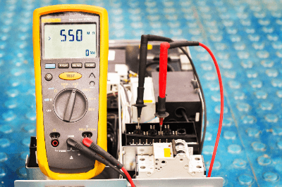
Insulation Resistance Testers

An insulation tester is a device used to diagnose insulation conditions. Insulation resistance testers capable of applying high voltages of about 1,000 VDC according to the system voltage are also available.

It is essential for any equipment that uses electricity to be well insulated. If the insulation deteriorates, it can cause electrical leakage, fire, or electric shock. To prevent the above accidents from occurring, it is necessary to evaluate the insulation performance periodically with an insulation resistance tester.

Usage of Insulation Testers

Insulation testers are used to quantify insulation capability. It is rarely seen in ordinary households.

In production, they are used for the final testing of electrical products at the factory where they are shipped. In addition, maintenance personnel of electrical equipment often have it as a measuring instrument for maintenance.

Resistance measurement involves the application of a voltage, and the applied voltage varies according to the system voltage.

Insulation Tester Principle

Insulation testers include wiring terminals, switches, DC power supplies, ammeters, and current protection elements.

The wiring terminal uses two terminals: the ground terminal and the line terminal. The ground terminal is grounded, and the line terminal is connected to the measuring section for measurement.

By pressing the switch, a DC voltage created by a DC power supply is applied. The minute current flowing to the earth is called leakage current, and the insulation resistance is obtained by measuring the leakage current when the voltage is used with an ammeter.

Since a high-voltage is applied, the impedance is increased with a current protection element to prevent overcurrents from flowing in the circuit. Due to the existing protection element, the internal impedance of the insulation resistance tester is designed to be very high.

The insulation performance is better with a higher the insulation resistance value. The insulation resistance value will be extremely low if an insulation breakdown occurs.

Other Information on Insulation Testers

Insulation resistance testers measure the insulation condition of electric lines and electrical components installed in factories and homes.

Causes of insulation defects may include poor installation of electrical circuits, poor insulation between charging and non-charging parts, deterioration over time, deterioration of internal wiring, damage due to shorts in parts used, and damage to the housing. If left unattended, these problems can lead to extremely dangerous electrical leakage, fires, and electrocution.

To prevent such problems, shut off the power supply system and measure insulation resistance as soon as the leakage breaker trips or an electric shock occur during operation appears.
カテゴリー
category_usa

Noise Filter

What Is a Noise Filter?

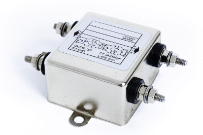
Noise FiltersA noise filter is an electronic component used to remove noise from a power supply or signal.
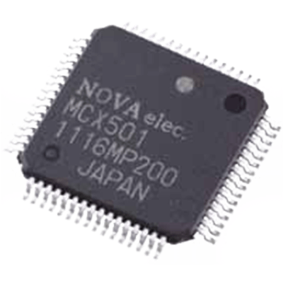
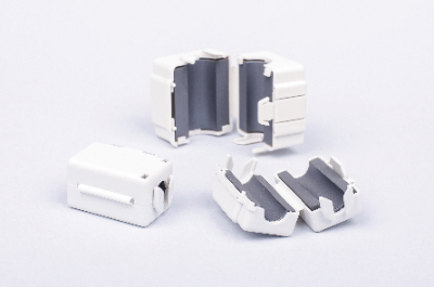
It is used in many electric and electronic circuits. When the current value in a communicating cable changes, a magnetic field is generated in the surrounding area. This magnetic field generates noise (abnormal signals) in the surrounding cable.

Noise filters can be installed to prevent the generation of noise. Note that using a device without noise filtering may cause malfunctions or failures.

Uses of Noise Filters

Noise filters are widely used in acoustic and industrial equipment.

The following are examples of noise filter applications:

  • Prevention of noise in speakers
  • Prevention of noise inside radio equipment
  • Power supply lines of PLCs, PCs, and servers
  • Inverter power circuits and thyristor power circuits

Noise filters are mainly used for receiving equipment that want to avoid noise and for output equipment that generates noise. Speakers and radios are devices that you want to eliminate the effects of noise, and noise filters are attached to communication lines. In this case, noise is a source of noise.

Computers such as PLCs also want to avoid malfunctions caused by noise, so noise filters are sometimes attached to power supply lines and so on. On the other hand, inverters and thyristors are devices that generate noise.

Since current and voltage changes in the secondary side circuit may be steep, noise filters are used to remove generated noise by smoothing it out. When smoothing the generated current, a reactor is generally used.

Principle of Noise Filters

Noise is transmitted in two main ways: radiation noise, which is radiated directly into space from inside electronic equipment, and conducted noise, which is transmitted through power supply lines and electronic circuit wiring and causes interference to other electronic equipment. It is generated as noise, for example, when radio waves of different wavelengths are introduced into radio waves of various wavelengths.

To prevent this noise, a filter (low-pass filter) is used to cut high-frequency signals if the main cause of the noise is high frequency. On the other hand, if the noise is low-frequency, a filter that cuts low-frequency signals (high-pass filter) is used.

Inductors and capacitors are the most common types of filters that act as low-pass filters. An inductor has a low impedance for low-frequency signals and a high impedance for high-frequency signals. Therefore, inserting an inductor in series in a circuit, allows low-frequency signal components to pass through more easily, while allowing high-frequency components to pass through less easily.

Capacitors, on the other hand, have the opposite characteristics of inductors. Combining a capacitor and an inductor makes a noise filter that cuts low and high frequencies.

How to Select a Noise Filter

Two important factors in selecting a noise filter are the rated voltage and the rated current.

1. Rated Voltage

Use a voltage lower than the rated voltage (maximum operating voltage) specified for each product. Some manufacturers take voltage fluctuations into account and may allow the use of a voltage higher than the rated voltage.

2. Rated Current

As with voltage, each product has its own upper limit for current. In particular, current characteristics tend to change depending on the ambient temperature, so it is necessary to check the environment in which the product will be used in advance.

As the ambient temperature rises, the allowable load current gradually decreases. Although a current in excess of the allowable current will not cause a serious problem for a short period of time, repeated current flow may cause a failure. In addition, DC power supplies, etc., may generate inrush currents, and noise filters should be selected by considering the current value and duration of the inrush current.

Other Information on Noise Filters

Precautions for Using Noise Filters

Ground wiring is also important for noise filters. The ground wiring should be as thick and short as possible. If the ground wire is long, an inductance component will act on it, which may degrade the attenuation characteristics.

It is also important not to tie input/output wires together or wire them close together. If the input/output wiring is close together, high-frequency noise components will bypass the filter and the desired filtering effect will not be achieved.

カテゴリー
category_usa

Motion Controller

What Is a Motion Controller?

Motion Controllers

A motion controller is a device that controls the motion of equipment driven by servomotors or other devices.

The user programs the motion to be realized in advance, and the motion controller executes it to control the motion of the equipment.

Uses of Motion Controllers

Motion controllers are used to control equipment driven by servomotors or linear motors. Therefore, they are applied to industrial robots and machine tools.

Specific applications are as follows:

  • For control of cooperative robots
  • For control of packaging machines for general consumables
  • For control of commercial printing machines
  • For control of high-speed press machines
  • For control of automatic assembly robots

Principle of Motion Controllers

The principle of motion controllers differs depending on the output method.

Typical output methods are as follows:

1. Common Pulse Method

The common pulse method controls a motor with a rotation direction signal and a pulse driving command. The rotation direction signal controls forward and reverse rotation direction, and the pulse driving signal drives the motor.

2. 2-Way Pulse Method

The 2-directional pulse system is a system that controls the motor with two commands: an FWD pulse operation command and an REV pulse operation command. The motor is driven forward by an FWD pulse operation command and reversed by an REV pulse operation command.

3. Phase Difference Input Method

The phase difference input method determines the direction of rotation based on the phase difference between two pulse signals. Forward rotation is made when the reference pulse signal advances  90° and reverse rotation is made when the reference pulse signal lags 90°.

How to Select a Motion Controllers

Interpolation control is important when selecting a motion controller. Interpolation control is a method of synchronized control between multiple axes. There are two types of motion controllers: direct interpolation and circular interpolation.

1. Linear Interpolation

Linear interpolation is a control in which two motors are controlled simultaneously to move linearly to the desired position. The CPU performs calculations and control so that the motion moves in a straight line in a diagonal direction, rather than moving horizontally and then vertically. Since linear interpolation enables a linear move in the diagonal direction, the time required for positioning can be shortened.

2. Circular Interpolation

Circular interpolation is a control method in which the CPU calculates the movement to draw a circular arc when two motors are controlled simultaneously. Since the movement path is not linear, it takes longer to reach the target position than with linear interpolation. However, by using arc interpolation, it is possible to avoid obstacles on the route.

Other Information About the Motion Controllers

1. Features of Motion Controllers and PLCs

Motion controllers are similar to PLCs in that they automatically control equipment with user-custom programs. Motion controllers are unique in that they are better suited to control servo systems.

Motion controllers are often used for motion control instead of PLCs. One advantage of motion controllers is that they are suited for controlling multiple axes and synchronization when the total number of axes is large.

While PLCs are limited in the number of axes that can be controlled by a single PLC, motion controllers can control far more axes than that. For this reason, motion controllers are used in industrial machine tools and robots that require precise, multi-axis control.

2. Motion Controller and PLC Programming

The principle of PLCs and motion controllers differs in the method of processing in the CPU: PLCs are multitasking controllers that read all lines of the program each time they are executed and execute all lines at once. Therefore, the time required to read all lines of the program is the rate-limiting factor, and not enough computing time is available to perform complex control operations.

Motion controllers differ from PLCs in that the program is read and executed one line at a time. Therefore, compared to PLCs, the arithmetic processing required for one task is shorter, enabling high-speed processing.

In addition, the processing time of a single line of a motion controller is not affected by the increase in program capacity. Therefore, motion controllers can process complex systems such as servo motors at higher speeds.

カテゴリー
category_usa

Ferrite

What Is a Ferrite?

Ferrites

A Ferrite is a ceramic composed mainly of iron oxide and is used as a magnetic material.

Because it is ceramic, its electrical resistance is higher than that of metallic magnetic materials and is characterized by excellent corrosion and chemical resistance.

Uses of Ferrites

Ferrites are mainly used as a magnet called ferrites magnet. Because it is inexpensive and can be mass-produced, its use fields are diverse, including home appliances, game consoles, and personal computers.

Ferrites are also used as the core of transformers and as a material to block electromagnetic waves in radio wave anechoic boxes and anechoic chambers. Ferrite particles are also used as carriers to carry toner in laser printers, etc. Ferrites are a magnetic material that permeates our daily lives.

Types of Ferrites

There are three types of ferrites as follows.

1. Spinel-Type Ferrites

Spinel-type ferrites are ferrites whose main component is Fe2O4. In the past (because its main component was iron oxide) it had to be heat-treated at a temperature of 800°C or higher to be produced.

In recent years, it has become possible to produce it at temperatures as low as 100°C by conducting the reaction in an alkaline solution. Spinel-type ferrites exhibit soft magnetic properties when mixed with additives such as manganese, cobalt, nickel, copper, and zinc.

2. Hexagonal Ferrites

Hexagonal ferrites are ferrites with the chemical formula M-Fe12O19 (M: Ba, Sr, Pb, etc.). It is hard ferrites that exhibit complex magnetism when barium or strontium is added.

3. Garnet-Type Ferrites

Garnet-type ferrites are ferrites with the same type of crystal structure as natural pomegranate stone and have the chemical formula Mg3Al2Si3O12. Garnet-type ferrites are soft ferrites that exhibit the same mild magnetic properties as spinel-type ferrites.

Other Information on Ferrites

1. Properties of Ferrites

  • Hard Ferrites: Hard ferrites have ferromagnetic properties that become magnetic once a strong magnetic field is applied and then remain magnetic.
  • Soft Ferrites: Soft ferrites have weak magnetic properties that develop magnetization when a magnetic field is applied and cease to be magnetic when the field is removed. It is characterized by its high magnetic permeability and is used in the cores of coils and transformers.

2. Mechanism of Noise Reduction by Ferrites

Ferrites are also used as a noise-reducing component. For example, EMI (Electromagnetic Interface) is a significant problem in high-speed communication signals such as USB, etc. EMI (Electromagnetic Interference) is not limited to communication lines but refers to unwanted electromagnetic noise emitted by electrical equipment.

In terms of EMI certification and quality assurance, electrical equipment is classified as Class A or Class B, and appropriate EMI countermeasures are required for each product. Usually, EMI countermeasures are taken at the time of circuit and pattern design, but ferrites may be used in the later stages of design and when development time is limited.

By wrapping the ferrites around the noise-generating harness, the impedance of the cable changes according to the magnetization of the ferrites, and as a result, the noise current can be reduced. However, reducing noise current means that high-frequency components are reduced. In other words, the ferrites function as a simple low-pass filter.

Thus, it is essential to keep in mind that reducing high-frequency components leads to signal distortion, which may cause waveform accentuation and, eventually, signal quality degradation. The noise reduction characteristics of ferrites are determined by their impedance, which varies depending on the ferrite’s material, size, and number of turns.

When the ferrite material is the same and when the exact size is used, the impedance generally increases with the number of turns N in the harness. Although the increase in impedance results in more powerful noise suppression, the number of turns should be selected according to the frequency band to be suppressed.

The cross-sectional area also affects the impedance, and as a rule,  ferrites with a smaller inner diameter and a larger outer diameter have a higher impedance. A wide range of ferrites are available as high-frequency countermeasure components. It is important to understand the characteristics of each and use ferrites with the appropriate characteristics for the frequency band to be counteracted.

カテゴリー
category_usa

Terminal Block

What Is a Terminal Block?

Terminal Blocks

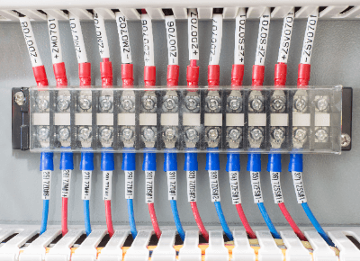
A terminal block is a row of terminals that connect external wiring to internal circuits. They are used in distribution boards and power distribution boards.

Electric wires are treated with crimp terminals and fixed to the terminal block. Screw-fastening and screwless types are available for terminal blocks.

Two-stage types and oil-and chemical-resistant types are also available. Voltage and continuity can be measured on the terminal block using a tester.

Uses of Terminal Blocks

Terminal blocks are used to connect circuits inside the panel to external wiring. Terminal blocks are used in distribution boards, switchboards, breakers, noise filters, aerospace, relays, air conditioning controls, and more.

Depending on the application, there are many types of terminal blocks to choose from. For example, for interface use, there are dedicated interface terminal blocks that are compact and convenient with many terminals. In addition, terminal blocks for grounding, fuses, and other applications are available.

Principle of Terminal Blocks

Terminal blocks are divided into conductive boards and components such as plastic girders.

Conductive boards are made of conductive materials and are used to conduct electric current between wires. The plastic frame is the part that insulates the electric circuit to prevent ground faults.

Crimp terminals are used to connect the conductive plate to the wires. Although crimp terminals alone may be used, it is safer to protect them from electric shock with marked tubes or insulating caps.

The crimp terminal is clamped under the screw attached to the conductive plate. The current can flow through the conductive plate. Generally, do not fasten more than three wires to a single screw. The purpose is to prevent increased contact resistance.

Do not allow wires to ride on top of equipment or fixtures to avoid electric shock or ground fault. Before use, check the specifications of the terminal blocks to ensure that the current and voltage are within the allowed range.

Screwless types are convenient because they do not require terminals and can be used by stripping the wires and inserting them directly into the terminal blocks.

Resin mounts are available in thermoplastic and thermosetting resins, which differ in heat and chemical resistance. Screws and conductive plates are made of copper, stainless steel, chrome plating, or other conductive metals, and many products are RoHS compliant.

Types of Terminal Blocks

Apart from the classification of connection methods, there are convenient terminal blocks with various functions.

1. Common Terminal Blocks

Standard terminal blocks, in which each terminal connection is connected internally, are mainly used for power distribution. 10-circuit, 20-circuit, plug-in type, screw connection, and other types are available and are selected according to the specifications of the equipment.

2. Connector Terminal Blocks

Connector terminal blocks are used to convert connectors of various standards into terminals. Connectors are connected to terminal blocks, and wires are connected to the terminals corresponding to the connector pins without soldering.

Many connectors can be used, and products compatible with various connectors such as D-Sub, MIL, and FCN are available. Terminal connections are also available with screw connections, plug-in types, etc.

Connector terminal blocks are often used for IO connections to PLCs; I/O can be input/output to PLCs by connecting the IO connector of the PLC to the connector terminal blocks with a cable and wiring I/O to the terminal blocks, thereby reducing wiring person-hours.

カテゴリー
category_usa

Mica Capacitor

What Is a Mica Capacitor?

A mica capacitor is a capacitor that uses a natural mineral ceramic called mica as the dielectric.

These capacitors have very high heat resistance and good temperature characteristics. Mica is used in thin layers, which are peeled off one by one. The mica layer is easily cracked, making it more difficult and expensive to process than other capacitors.

In recent times, the share of ceramic capacitors has been decreasing due to their improved properties, although they continue to be preferred for audio-related applications.

Uses of Mica Capacitors

Mica capacitors were popularly used in vacuum tube amplifiers and power conditioners, especially in the 1970s and 1980s. The sound quality unique to mica capacitors has attracted attention, and some models are used in high-end audio amplifiers.

It was used in almost all electronic equipment such as radio communication equipment and electronic calculators around the time of World War II. Later, they were also used in televisions, radios, etc. However, due to their high cost, inexpensive capacitors have become the mainstream in recent years.

Principle of Mica Capacitors

1. Characteristics

Mica capacitors utilize the natural mineral mica as their dielectric material. Mica is a silicate mineral, and because it is made from a mineral, it maintains stable characteristics even at high temperatures. It also has good high-frequency characteristics.

Capacitance tolerance, which indicates the accuracy of capacitance, can be made very small, and since equivalent series resistance is small, the dielectric loss tangent can be kept small.

2. Capacitance

The capacitance of a capacitor increases as the electrode area increases. A mica capacitor consists of thinly peeled mica plates and silver foil alternately stacked in a sandwich-like structure. The purpose of sandwich layering is to make the capacitor smaller while increasing the electrode area.

Mica is an unusual mineral in that it is thin and easily peeled off, and it also has excellent electrical insulation properties. The mica capacitor was conceived based on these characteristics of mica. Some capacitors use a technique called a paper capacitor, in which the electrodes and dielectric are rolled up like a scroll to increase the electrode area.

Types of Mica Capacitors

There are two main types of mica capacitors: the stacked type, in which metal foil such as tin and mica are alternately arranged on the electrodes, and the silver paste printed on mica and layered on top of each other. The silverado-type has better characteristics because it is heat-compression bonded and is used in more situations than the stacked type.

Mica includes white mica and biotite, and its form and color vary slightly depending on the composition of the raw material. Its quality and composition vary slightly depending on the region of origin and the part used, and since it is a naturally occurring mineral, it is more difficult than other capacitors to maintain stable quality.

In addition, the process of carefully peeling off the thin layer of mica must be done by hand, so the cost is higher because of the skill required.

Other Information on Mica Capacitors

Role of Mica Capacitor

The basic structure of a capacitor consists of two electrodes facing each other with a gap between them; when a DC voltage is applied to the two electrodes, electrons momentarily gather on one electrode and become negatively charged, while the other electrode becomes positively charged due to a lack of electrons.

This state is maintained even after the application of DC voltage is stopped, and an electric charge is stored between the two electrodes. When a dielectric is inserted between the electrodes, the dielectric polarization of the dielectric increases the stored charge. Mica capacitors use mica as the dielectric.

The dielectric constant measured at 50Hz is 6.5~9, which is higher than that of other materials. Mica is also suitable for dielectrics because of its heat resistance and insulating properties and its thin film form.

カテゴリー
category_usa

Trimmer Capacitor

What Is a Trimmer Capacitor?

A trimmer capacitor is a variable capacitor used for fine-tuning circuits and compensating for component variations.

The capacitance is adjusted by mechanically turning a knob with a screwdriver. They are also called semi-fixed capacitors because they are set during manufacture or service and are not shifted once they are in use. Mostly used for surface mounting, they are basically chip-type or round. They are often used to adjust the oscillation frequency of quartz crystal units.

Trimmer capacitors use the capacitance method, and capacitance can be adjusted by changing the effective surface area between electrodes, the distance between electrodes, or both.

Uses of Trimmer Capacitors

Trimmer capacitors are often used in oscillation and radio circuits, including quartz crystals, for frequency adjustment. Examples include keyless entry for automobiles, automatic ticket gates at train stations, handheld radios, power amplifiers, and RF modules for Bluetooth.

Other applications include radios, clocks, electronic pens for PCs, DVDs, hybrid ICs, and surveillance cameras. Nonmagnetic trimmer capacitors are often used in medical equipment such as MRIs.

Principle of Trimmer Capacitors

Trimmer capacitors have variable capacitance within a certain range. Like an ordinary capacitor, an insulator is sandwiched between two electrodes, which store an electric charge when a voltage is applied. The capacitance can be adjusted by moving one of the electrodes.

Air or ceramic is used as the dielectric. Trimmer capacitors have a small capacitance at the pF level because their structure does not allow them to be made with a large capacitance. Movable electrodes are often round in shape and can be shifted by rotating them with a knob or similar tool, using the center axis or outside of the electrode as a guide.

Since the surface area of the displaced electrode changes, the capacitance can be varied. During the initial setup, a screwdriver is used to adjust according to the application. Once adjusted, the capacitance is basically fixed and used without changing. When adjusting with a screwdriver, care should be taken not to apply excessive force as it may cause damage.

Structure of Trimmer Capacitor

The structure of a trimmer capacitor is the same as that of a general capacitor, except that it has a screwdriver slot and a metal rotor for adjustment. Note that because of this structure, if the soldering iron adheres to any part other than the terminal area, flux solder may enter the variable area and fix the rotor or prevent it from making contact.

Also, if the tip of the soldering iron touches the covered trimmer capacitor, it may melt or damage the capacitor.

Other Information on Trimmer Capacitors

1. How to Adjust Trimmer Capacitor

To adjust the trimmer capacitor, use a screwdriver to rotate the rotor to the desired capacitance setting. There are two types of screwdrivers for adjustment: one for manual adjustment and the other for automatic adjustment.

Ensure that the screwdriver is placed in the groove for the driver, and after a preliminary rotation of 360° or more, set the capacitance. When adjusting with a screwdriver, it is recommended to use a load of 1N or less. Applying a load greater than this may result in damage or loss of function.

The stray capacitance when adjusted with a screwdriver can be reduced by attaching the negative terminal to the ground of the circuit.

2. Colors of Trimmer Capacitors by Capacitance Rank

Some trimmer capacitors have different color cases according to their capacitance ranks. The color classification differs depending on the manufacturer, but the following are some examples:

  • Capacitors with a maximum capacitance (pF) of 3.0 +50/-0% are brown in appearance.
  • Those with a maximum capacitance (pF) of 6.0 +50/-0% are blue in appearance.
  • 10.0 +50/-0% of maximum capacitance (pF) is white.

Some capacitors have not only colors but also indications as shown below:

  • Those with a maximum capacitance (pF) of 50.0 +100/-0% have a black exterior + indication

Indication will include the shape of the terminals and whether or not a cover film is used. Thus, color-coded trimmer capacitors allow the eye to easily determine the capacitance, thus reducing the risk of using the wrong one.

カテゴリー
category_usa

Constant Temperature Bath

What Is a Constant Temperature Bath?

A constant temperature bath is a type of apparatus used in scientific experiments.

There are two types of thermostatic chambers: one that changes the air temperature and the other that changes the water temperature (thermostatic tank). The size and specifications vary depending on the application and purpose, ranging from table-top types, large refrigerator-like types, to types in which a single room can be adjusted as a constant temperature bath.

Uses of Constant Temperature Baths

Major types of constant temperature chambers include incubators, constant temperature dryers, constant temperature water baths, and environmental test chambers (cycle testers, constant temperature/humidity chambers, etc.). Incubators are used in scientific experiments to culture microorganisms and cells. In the industrial field, incubators are used to hatch eggs, and in the medical field, incubators are used to maintain the body temperature of low-birth-weight infants. Thermostatic dryers, thermostatic water baths, and environmental test chambers are widely used in biochemistry, organic chemistry, and other fields, and are used for a variety of analytical testing purposes.

Principle of Constant Temperature Baths

A constant temperature bath basically consists of a vessel that maintains temperature, a heating (or cooling) device, a temperature sensor, and a temperature controller. Humidifiers and dehumidifiers are used to control humidity, and fans and agitators are installed to equalize the temperature inside the vessel, depending on the application. The temperature is varied by a heated humidifier, cooler, or dehumidifier, and maintained at the desired temperature by a temperature sensor.

Constant temperature baths are designed primarily to maintain a constant temperature, but depending on the application, the temperature can be programmed to rise and fall repeatedly at regular intervals, or to rise and fall at a constant gradient.

Setting an arbitrary program depends on the plugram device in the constant temperature bath itself and thus on the functionality of the individual product. If the product has a built-in communication interface, it can also be operated remotely using a personal computer. Data can be recorded directly into the constant temperature bath’s internal memory or into an external device, depending on the application.

Structure of a Constant Temperature Bath

Constant temperature baths range in size from 30 cm to several meters on a side, and can be installed in a laboratory.

The general structure of a thermostatic chamber is that it has a door and insulation to prevent temperature changes from the surrounding environment. The inside of the chamber is sealed off from the outside world. In addition, controls are installed to maintain a constant temperature for an extended period of time.

In terms of individual components, constant temperature baths are divided into two types: those that have the entire bath covered by an outer frame and those that do not. In both cases, a case is installed to hold water, and the temperature is controlled at or below the evaporation temperature of the water. In addition, when experiments are conducted at temperatures of 100°C or higher, water cannot maintain the temperature, so some devices use oil to heat the water.

Other thermostatic dryers have timers and temperature increase programs that allow the temperature and temperature increase rate to be set according to the experimental application.

Uses of Constant Temperature Baths

Constant temperature baths are generally used in laboratories, etc., and are often used in water/oil baths and constant temperature dryers.
Thermostatic water/oil baths are mainly used in chemical and biological experiments, where samples are placed in flasks and stirred to maintain a constant temperature.

The usage is simple: fill the tank installed in the instrument with water or oil and set the temperature. However, since experiments are conducted for long periods of time, care must be taken to avoid burns.

Constant temperature dryers and constant temperature-humidity baths are used not only in experiments but also in drying semiconductors, cultivating microorganisms, and drying various instruments.

The usage is simple: open the door, place a sample inside the chamber, set the temperature increase rate, target temperature, holding time, etc., and perform drying and sample observation. In addition to heating, some instruments are equipped with a cooling function that allows them to be used for low-temperature experiments. However, since they may use chlorofluorocarbons or other refrigerants, they need to be outsourced to a specialized contractor.

On the other hand, constant temperature baths using Peltier elements are also available in recent years. Peltier elements can perform cooling and heating by changing the direction of electric current. They are characterized by power savings, CFC-less, small size, and fine temperature control.

カテゴリー
category_usa

Counter

What Is a Counter?

Counters

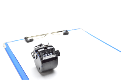
A counter is a device, tool or part that counts. 

When counting, a small number can be easily counted and memorized, but when the number is large, it becomes difficult to do so by memory alone. Therefore, a counter is a device that counts numbers correctly on behalf of a human being.

Uses of Counters

Counters are used to help people remember numbers, and are called counters. Counters are used to count the number of cars passing by in traffic surveys, for example. Currently, it is possible to replace counters with smartphone applications.

There are also counters that are incorporated into industrial equipment as electrical components. They are called digital counters and are mainly used inside control panels at production sites.

Types of Counters

Digital counters include preset counters and total counters.

1. Preset Counter

A control signal is output when the count reaches a preset value.

Common input signals are pulse signals and contact open/close signals. Digital signals such as contact outputs or transistor outputs are used as output signals.

When it is desired to stop the output of the counter, a reset process is performed. Reset processing can be done with a pushbutton or by short-circuiting the reset terminal.

Many preset counters require an auxiliary power supply to supply electricity to the counter itself. Auxiliary power supplies can be purchased in AC or DC power supplies of your choice.

2. Total Counter

This counter has only the function of displaying the count value. It counts contact and pulse inputs and displays the count value on an output screen.

The total counter can also be reset to zero. Reset processing is performed with the pushbutton or reset terminal as with the preset counters.

Many total counters are also available with a built-in battery, eliminating the need for an auxiliary power supply. In addition to the above, there are also time counters that measure the duration of contact output.

There are also addition counters that increase the count value for each signal input and subtraction counters that decrease the count value in the opposite direction. Since there are many types of counters and their specifications vary, it is necessary to select the right counter for the right application.

Counter Principle

In the case of a counter, a human-powered pushbutton turns a character wheel to produce an output. The internal circuit only uses gears to drive the character wheel, and the reset button also manually returns the character wheel to 0.

Digital counters are mainly divided into three parts: the display section for displaying the count value, the internal circuit for receiving input signals and performing operations, and the operation section for resetting or presetting the value.

Input signals are sent to the counter in a variety of ways, including input by pushbuttons and digital input using sensors. Digital counters are generally input by contact. A pushbutton with a contact can be used to convert the input to a pushbutton input.

The internal circuitry always holds the current value. The initial value is generally 0, but it can be set arbitrarily. Upon receiving an input signal, the counter’s internal circuitry displays the current value plus one on the display.

When a preset counter is used, the output signal can be sent out by performing a preset. The preset value is compared with the current value, and if it is equal to the set value, an output signal is output.

When the operation is completed, the counter enters a state waiting for an input signal and prepares for the next operation. By repeating these series of operations, the counter counts the number of digits and continues to display the number of digits on the display.

The display section can be character wheel or digital. Most of the counters that use a character wheel are called electromagnetic counters, and they make use of an electromagnet to turn the character wheel. Electromagnetic counters have the advantage of maintaining the display even without a power source.

In recent years, counters with digital displays are also widely used. Digital displays require a power supply, but light-emitting ones have the advantage of being easy to see in the dark.

カテゴリー
製造業マーケティングガイド

【事例紹介】ライカマイクロシステムズ株式会社様


複数の業務に関わる担当者が新規顧客の流入を片手間で増やした方法


「From Eye to Insight」をビジョンとして掲げ、創業から170年以上光学顕微鏡の製造・販売を手がけているライカマイクロシステムズ株式会社。

ライカ マイクロシステムズでは外資系企業では珍しく、日本法人として自社サイトを運営しており、オンラインマーケティングにも力を注いできました。しかし、営業責任者である矢倉様がマーケティング業務を兼務で行っていたため、充分なSEO対策などを行うことができず、自社サイトへの流入数が増えないことに課題感を感じていました。

兼務しながらでも、自社サイトの流入数を伸ばし、新規顧客を獲得するためにSEO(検索エンジン最適化)や掲載の手軽さに強みを持つMetoreeの導入を決断しました。その背景や導入に対してのハードル、導入してからの変化などについて矢倉様に伺いました。


無料掲載ご希望の方はこちら


170年以上の歴史を持ち、質の高い光学顕微鏡を届ける


―はじめに、御社の事業についてお教えください。

矢倉さん(以降、矢倉):世の中的にはライカというとカメラのイメージが強いと思いますが、これは関連会社のライカカメラという会社が行っている事業です。弊社は、「From Eye to Insight」をビジョンとして掲げ、創業から170年以上光学顕微鏡の製造・販売を行っております。大学や病院などで利用される高度な顕微鏡から、一般企業で利用される顕微鏡まで幅広く販売させていただいております。

―矢倉さんの役割についても教えてください。

矢倉:その中で私は主に製造業企業向けの販売を担当するインダストリーの事業部の営業責任者を務めており、傍でマーケティング業務を行っています。メインの営業責任者としては営業チームのマネジメントやKPI管理、チームの環境づくりなどを行っております。マーケティング業務は専任がいないため、広告出稿やコンテンツ作りなど幅広く担当させていただいております。


サイトへの流入数を増やすためにMetoreeを選択


ーMetoree掲載前はどのように問い合わせの獲得をしていたか教えてください

矢倉:コロナがはやる前は、オフラインのイベントや展示会への出展を通してリードの獲得を行っていました。イベント出展以外にもオフライン、オンライン問わず広告出稿を行っていました。コロナの影響でイベントなどを行えなくなったことも大きかったのですが、投資対効果の観点でも会社としてオンラインでのリード獲得に力を入れていきたいという考えはありました。

また、弊社は外資系企業では珍しく、日本法人として自社サイトを運営しております。兼務でマーケティング業務を行っているため、積極的に運用できるわけではありませんが、自社サイトのコンテンツの拡充をすることでサイトへの流入を増やし、リード獲得に繋げていました。

ーどんなところに課題があったか教えてください

矢倉:大きく分けて二つ課題がありました。一つ目はコンテンツを作りづけるリソースが足りなかったことです。先程もお話ししましたが、マーケティングは私が兼業で行っているため専任の担当者はいません。そのため、魅力的なコンテンツを継続的に作り続けることは難しい状況でした。

二つ目は流入を増やすことができなかった点です。自社サイトを運用しているため比較的自由にコンテンツを増やすことはできましたが、リソースが不足していたためSEO(検索エンジン最適化)対策などを行うことができず、コンテンツを増やしてもサイトへの流入が増えないという課題を感じていました。

ーどんな経緯で広告を出すことになったんですか?

矢倉:元々オフラインの広告媒体やGoogleのリスティング広告などで広告出稿自体は行っていました。しかし、こちらもリソース不足で運用が回っておらず、新規顧客の獲得には繋がっていない状況でした。そんな時に関連会社からMetoreeを紹介してもらいました。

MetoreeはSEOに強みを持っており、当時からGoogle等の検索エンジンで光学顕微鏡関連のキーワードで検索すると上位に表示されていました。自社サイトへの流入数が大きな課題になっていたので、流入数を増やすための新しいチャネルとしてメトリーさんへ掲載をお願いすることにしました。


月間問い合わせ数の1割をMetoree経由で獲得


ー広告媒体は他にもあったと思うのですが、なぜMetoreeを選んだのですか?

矢倉:もちろん他の媒体への広告出稿も考えましたが、一番の決め手は掲載の手軽さと掲載へのスピードだと考えてます。どうしてもマーケティング業務を兼務しているため、コンテンツを自ら作成して更新し続けることは、手間も時間もかかってしまいます。また一般的に記事広告などの掲載には数ヶ月かかるケースが多く検証までに期間がかかります。

Metoreeは、リンクと商品説明のバナーやテキストだけ用意するだけで、掲載することを決めた日から1日〜3日程度で手軽に開始することができることが大きなメリットだと感じています。また、Metoree自体がSEO対策がしっかりされているので、多くの製品ページがGoogleで上位表示されています。そのためコンテンツを自社で作成しなくてもいいので、兼務している私でも続けることができると思いメトリーの導入を決めました。


ー掲載後はどのような効果がありましたか?

​​矢倉:Metoree掲載後は、ホームページへの流入数を増やすことができ、月間問い合わせ数の1割はMetoree経由で獲得することができています。また、リスティング広告などと比べると、ターゲットとしているお客様が問い合わせをいただいている印象があります。

リスティング広告では、どうしてもターゲットとしていない属性のお客様が入ってきてしまうこともありました。Metoreeは産業用製品専門の製品情報比較メディアなので、一定フィルタリングされているため、ターゲットになるお客様が多い印象を受けています。


手軽さと無料で始められることがメリット


ーMetoreeに掲載するなら、どんな課題を持った方がおすすめですか?

矢倉:Metoreeの1番のメリットは、しっかりと流入数を増やすことができる媒体でありながら手軽に始められることだと考えています。実際に私もマーケティング業務を兼務しながら2年ほど運用をすることができています。そのため、業務を兼務していて自社のSEO対策に手が回らない人やマーケティングを兼務している人などにお勧めしたいです。また、無料から始めることができるので広告出稿の経験がない方でも気軽に始めることができると思います。


無料掲載ご希望の方はこちら


ライカマイクロシステムズ株式会社様の会社HPはこちら

ライカマイクロシステムズ株式会社様のマイクロスコープ紹介ページはこちら