What Is a Mechanical Valve?
A mechanical valve is a control valve that changes the flow of air operated by human power or by contact with an object.
To make an actuator such as a pneumatic cylinder work, it is necessary to switch the flow of compressed air freely. In the case of a single-acting cylinder, compressed air is supplied in the forward direction when moving forward, and in the reverse direction when moving backward, the compressed air is released into the atmosphere.
The valve that controls the direction of air flow is called a directional valve. Directional valves can be controlled in three ways: electrically, pneumatically, or by human or mechanical contact. A solenoid valve is operated by an electrical signal to open and close the valve, while a pneumatically operated valve is called a (air) pilot operated valve.
A mechanical control valve is operated by hand or foot, or by mechanical contact with an object, such as a limit switch. Such a control valve operated by human power or mechanical contact is called a mechanical valve because it is operated by mechanical action.
Uses of Mechanical Valves
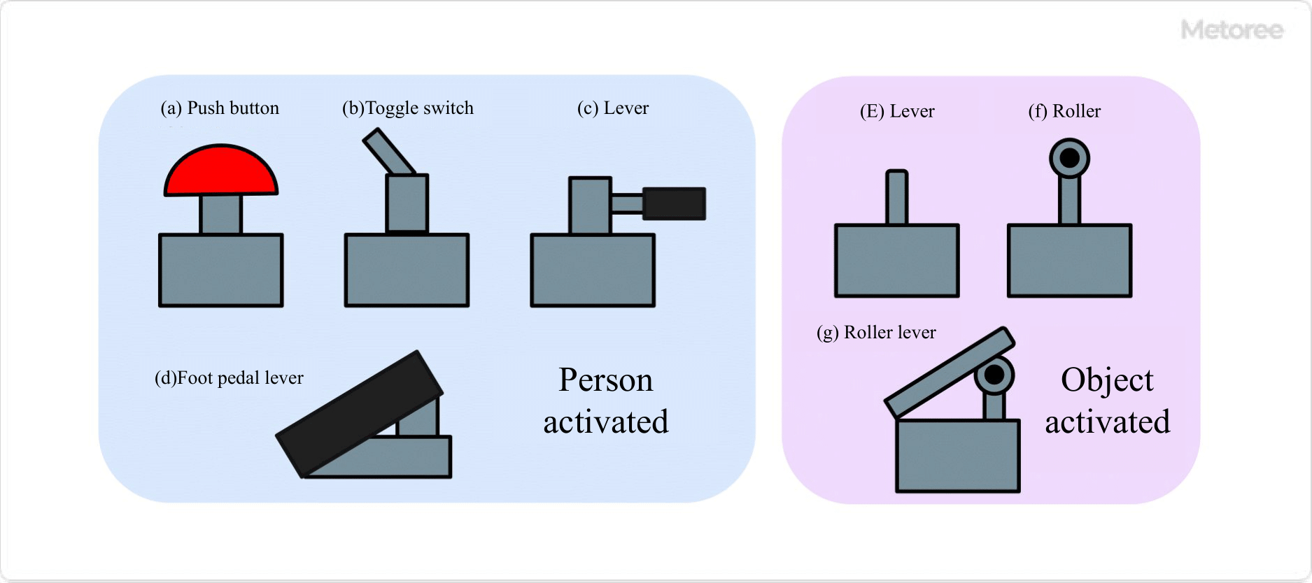
Figure 1. Classification of mechanical valves by method of operation
Mechanical valves are useful in places where fire is strictly prohibited and explosion-proof specifications are required. Since actuators such as pneumatic cylinders can be operated only with pneumatic devices without using electrical signals, there is no need to worry about leakage of electricity or electric shock.
Push buttons, levers, and pedal types are available for those operated by human hands and feet. Besides being used as supply shutoff valves installed at the entrance of equipment, they are mainly used in semi-automated equipment. They may also be used as start-up switches for air sequence control.
Those with mechanical operation include plunger and roller types. Used as a switch for cylinder operation or workpiece position confirmation, it generates a signal for air sequence control.
For example, it is possible to control the cylinder to stop moving automatically when the door is opened or to operate only when the door is opened.
Principle of Mechanical Valves
In mechanical valves, a button is pressed by a human, or a plunger is pressed by a door or workpiece, which releases a flow path or is blocked by a valve. This is the principle of changing the pressure of airflow.
There are three types of valve structures: poppet type, spool type, and sliding valve type. The poppet type has a simple structure but requires a large amount of force to operate. This makes the valve more sealed, making it suitable for high-purity gas lines.
The spool and sliding valve types can be operated with relatively small force, but require a longer stroke.
How to Select Mechanical Valves
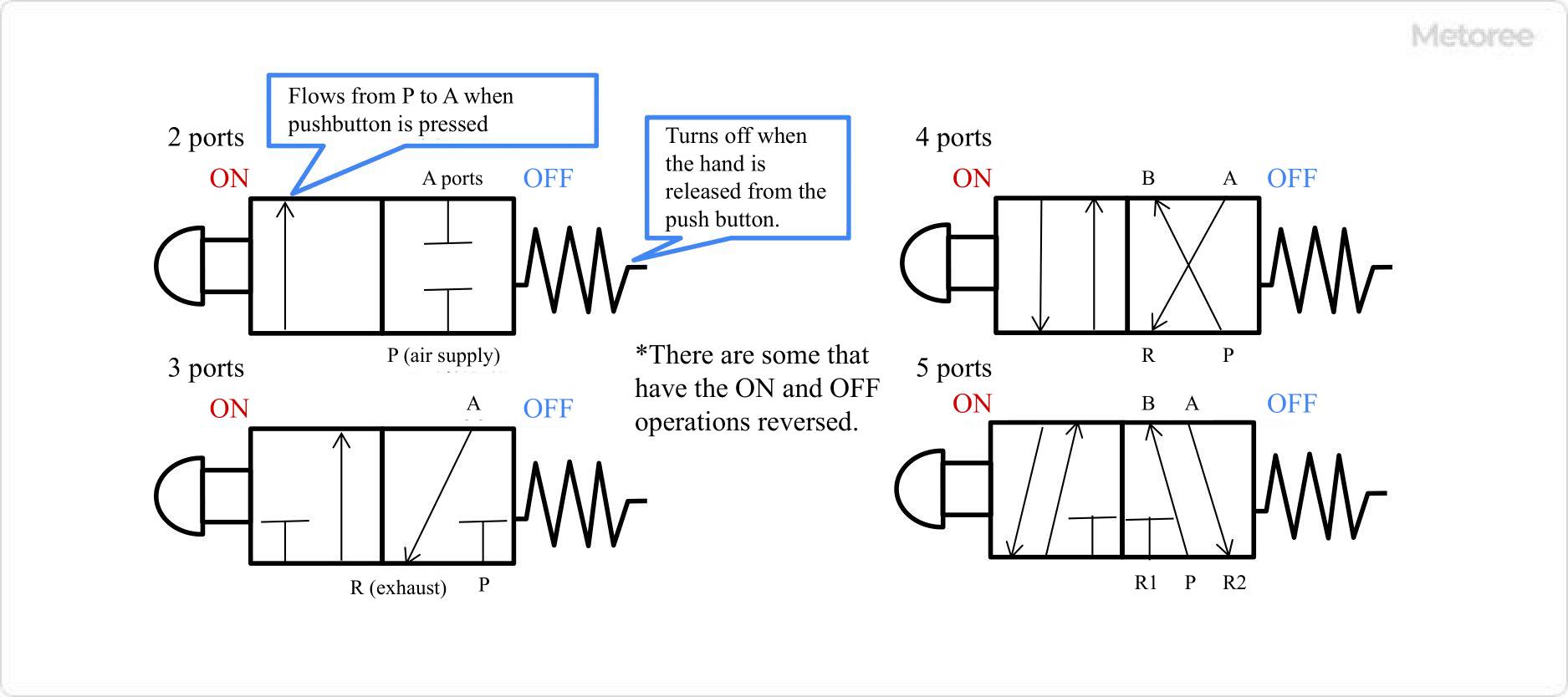
Figure 2. Difference in flow direction by port of 2-position mechanical valve (JIS symbol)
As with solenoid valves, the number of ports must be selected for mechanical valves as well.
2-Port Valve
A 2-port valve simply stops or diverts airflow. If you look at the 2-port, you will see a square on the left side, which means that air flows when the pushbutton is pressed. On the right side, the A and P ports are not connected, so no air flows.
3-Port Valve
A 3-port valve has an exhaust port and functions to supply and exhaust air. They are often used to operate single-acting cylinders or to signal air pilot lines. When the button is pressed, air flows from P to A. When the button is released, the air in A is exhausted out through the R port.
4- and 5-Port Valves
The 4- and 5-port valves have a function to intake air from the P port and supply and exhaust air alternately from the A and B output ports. One or two exhaust ports are available.
When connected to a double acting air cylinder, it can slide in both directions.
2. Position of Mechanical Valves
Depending on the number of switching positions the directional valve has, it can have two or three positions. For example, if the valve is designed to switch between state 1 and state 2 by “pushing” or “not pushing” a switch, it has 2 positions, and if it is a lever-type manual switching valve, it has a third state 3. In the case of a lever-type manual switching valve, a valve that has a third state (state 3) is in the 3-position. In the case of mechanical valves, state 3 is a 3-position closed center, which means that both ports A and B are sealed.
3. Method of Operation After the Button Is Pressed
A switch that returns to its original state by spring force when the button is released after being pressed is called a spring return type. A switch that retains the pressed state is called a retention type. It is also important to consider the operation after the switch is pressed when making a selection.
4. Other
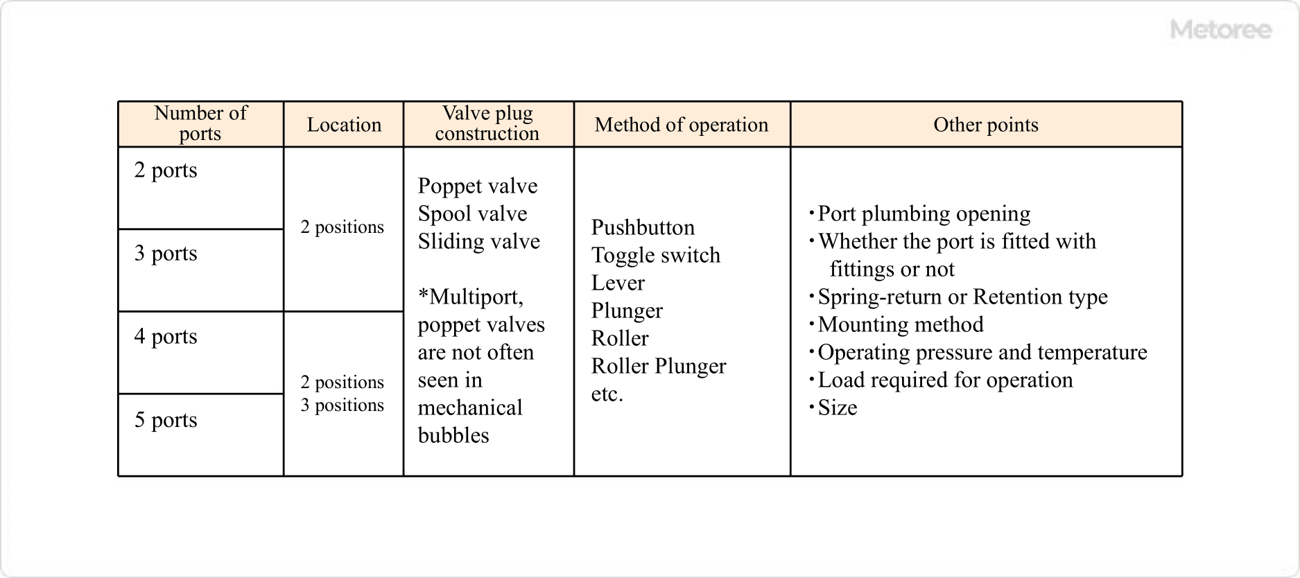
Figure 3. Classification of mechanical valves by method of operation
There are various other selection points, such as the size of the port piping opening and the operating pressure. Because of these various types, it is important to design the pneumatic circuit in advance and determine which components will be needed before purchasing.
Other Information on Mechanical Valves
Precautions for Using Mechanical Valves
Because the valve must be moved under pressure by compressed air, a large amount of force is required, especially for valves with poppet-type valves. For example, an object that is intended to push the plunger may be pushed back the other way. Be sure to check the catalog value, as it states how much load should be applied.
It is important to always use a filter in the compressed air supply circuit to all directional control valves to ensure that debris and condensate are removed. Select a filter with a filtering fineness of 5 µm or less.
Air pressure containing large amounts of condensate can cause malfunctions to other pneumatic equipment, so countermeasures should be taken by installing after coolers, air dryers, etc.