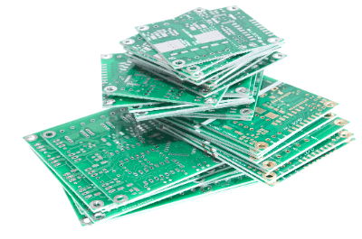
What Is a Conversion Board?

Conversion Board is a board for converting the pitch of narrow-pitch ICs, LSIs, microprocessors, etc. for mounting on a universal board with a pitch of 2.54mm for experiments and evaluations.
Conversion Boards are also used to realize connections with peripheral devices as the board’s functions are expanded after development. By connecting peripheral devices such as servo motors and LEDs using the communication terminals on the microcontroller board, control can be easily achieved.
Uses for Conversion Board
Conversion Boards are used to verify the design of circuits that incorporate ICs, LSIs, and microprocessors. Design verification is performed in an evaluation environment that includes the Conversion Board, and once the design is complete, a dedicated board is produced for final commercialization.
Conversion Board is not used after the design is completed, and the product board is a board on which ICs, LSIs, and microprocessors are directly mounted on a dedicated board for the product. The reason for this is that the cost of using a Conversion Board is higher.
However, if the design period is limited or the number of product boards to be produced is not so large, the product may be commercialized without using the Conversion Board.
Principle of Conversion Board
1. Connection to Microcontroller Board
Conversion Board converts the pin pitch of an IC, LSI or microprocessor to the 2.54mm pin pitch of a universal board. Functions such as general-purpose I/O and communication are assigned to the microcontroller pins, and these functions are also assigned to the pins of the Conversion Board.
When connecting a Conversion Board to a microcontroller, a Conversion Board that matches the functions of the pins to be used is required. By connecting a matching Conversion Board, electrical signals from the microcontroller can be transmitted to peripheral devices through the Conversion Board.
2. Use in the Evaluation Process
Many conventional ICs have a pin-to-pin pitch of 2.54mm and can be mounted directly on universal boards. As electronic devices have become smaller, lighter, and more sophisticated, the ICs, LSIs, and microprocessors that control them have become more sophisticated and smaller.
As a result, the pin pitch has become narrower and narrower, making it difficult to evaluate and verify by directly placing pins on them. Conversion Boards allow mounting on universal boards with a pin-to-pin pitch of 2.54mm, creating an environment that facilitates evaluation.
Other Information on Conversion Board
1. Target Board Standards
Conversion Boards are used to convert SMDs (Surface Mount Devices) to PGAs (Pin Grid Arrays), which are a type of package with a grid of short pins on the bottom of the IC.
Conversion Board from SMD to DIP (Dual in Line Package), from SMD to plated through-hole boards, etc., and then to QFP (Quad Flat Package), SSOP (Thin Shrink SOP), MSOP (Mini/Micro SOP), SOP ( Conversion Board to QFP (Quad Flat Package), SSOP (Thin Shrink SOP), MSOP (Mini/Micro SOP), and SOP (Small Outline Package) are also available.
After the IC is soldered to the Conversion Board, the pins from the Conversion Board are soldered to the through holes and inserted into the Universal Board.
2.Conversion Board Used for Expansion of Functions
The microcomputer for device control is mounted on the board together with peripheral components. After the product has been commercialized, if it is necessary to expand its functions, for example, to include a display unit such as an LCD or LED, a data Conversion Board is required.
A sub-microcontroller and peripheral components are mounted on the Conversion Board. The Conversion Board is then used to expand functions through communication between the microcontroller that originally controlled the system and the newly installed sub-microcontroller.