極低温輸送

監修:株式会社三光堂

極低温輸送とは

極低温輸送とは、医療・生命科学分野における試料・検体・医薬品などを極低温で輸送するサービスです。

極低温輸送では、ドライアイス (昇華温度-78℃) よりも温度が低い液体窒素 (沸点-196℃) を用い、一般的にはサンプルを-150℃以下に保ったまま輸送を行います。ワクチンや幹細胞などの医薬品や、研究上の各種生物サンプルなど、品質維持のために厳密な低温管理が必要な凍結サンプルの輸送に最適な輸送方法です。

極低温輸送の使用用途

極低温輸送は、医療やライフサイエンス分野など、品質管理が重要な生物サンプルを扱う輸送シーンで特に使用されます。

1. 医療 (治療) 

医療における用途では、下記のような物質の輸送が例として挙げられます。

  • ワクチン
  • 幹細胞やCAR-T細胞など、免疫療法・再生医療に用いられる細胞
  • 抗体医薬などのバイオ医薬品
  • 尿検体
  • 血液検体

これらは、医療機関と検査機関の間の輸送、転院などに伴う医療機関同士での輸送が行われています。

2. 生殖補助医療

生殖補助医療の分野において、転院や転居、海外での生殖補助医療など様々な事情から、採取した卵子・精子や受精卵の輸送が必要になる場合があります。極低温輸送は体外受精におけるこれらの凍結細胞の輸送にも用いられている技術です。具体的な輸送品としては、

  • 凍結胚
  • 卵子
  • 精子
  • 受精卵

などが挙げられます。

3. 試験・研究

ライフサイエンス分野においては、様々な生物由来試料が用いられ、時として研究機関同士などで輸送が必要となることがあります。これらの物質は、細胞組織や生物学的機能を損なわないように極低温にて取り扱う事が必要です。具体的なサンプルの例としては下記のようなものがあります。

  • 培養細胞 (iPS細胞、幹細胞を含む)
  • 動物サンプル
  • 動物由来の受精卵
  • 核酸 (DNA・RNA) サンプル
  • 血液・膜サンプル
  • 臨床研究サンプル一般 (治験サンプルなど)

4. その他

生物由来物質は、上記以外の分野でも用いられており、代表的な分野が動物飼育のための用途です。そのため、極低温輸送のその他の使用用途としては、家畜・飼育動物の繁殖・健康維持のため、牛などの精子、鶏用ワクチンなどが挙げられます。

極低温輸送の原理

1. 概要

極低温輸送では-150℃以下の温度帯で試料を安定輸送するため、ドライシッパーと呼ばれる専用の容器を用います。また、温度記録装置や温度ロガーを用いて温度のモニタリング・記録が行われる場合も多く、厳密な温度管理が行われています。

2. ドライシッパー

ドライシッパーは、液体窒素を容器内のスポンジに吸収させる仕組みになっており、スポンジからゆっくりと液体窒素が放出されます。この機構により、容器内を-196度位の極低温状態に長時間保つことが可能です。

ドライシッパーの種類にもよりますが、最大で2週間から20日間前後一定の極低温を保つことができるため、細胞品質の維持に最適な保管環境を作り出すことができます。転倒した際の窒素漏れにも対応できるよう、液体窒素を吸収できる液体窒素吸着剤も内蔵されています。

3. コールドチェーン輸送とハンドキャリー輸送

極低温輸送の輸送システムとしては、コールドチェーン輸送とハンドキャリー輸送とがあります。コールドチェーン輸送とは、物流システムにおける低温輸送の体系システムであり、トラックや飛行機など、低温輸送に対応した物流輸送網を用います。

ハンドキャリー輸送とは、専門のスタッフが集荷から最終目的地まで、ドライシッパーを手荷物で運搬する輸送形態のことです。特に、凍結胚の移送などの場合にこちらの形態が用いられます。

例えば、凍結胚の移送に際しては、国外での生殖補助医療などのため航空輸送が用いられることが多いですが、空港でX線検査を通してしまうと検体に損傷が起きる懸念があります。このような空港での検疫対応や、交通事情に合わせた臨機応変な対応など、ハンドキャリー輸送ではより細かい対応を確実に行うことができるというメリットがあります。

極低温輸送の選び方

極低温輸送には、国内輸送や国際輸送があり、輸送距離に合わせて適切なものを選択することが必要です。

極低温輸送に必要なドライシッパーは、購入もしくはレンタルで用意することができます。ドライシッパーの性能はメーカーや製品によって異なるため、輸送する生体試料や用途に応じて、適切なものを選ぶことが必要です。容器のサイズも複数あるため、輸送する生体物質の数に応じて選択する必要があります。レンタルサービスでは、一般的に下記が一式セットになって提供されています。

  • ドライシッパー本体や容器ケースなどの梱包一式
  • 液化窒素充填
  • 使用方法のサポート
  • お客様、または移送元までの配送費用

また、-150℃以下の極低温輸送サービスを提供している企業は、2~8℃、15℃~25℃、-20℃、-80℃の温度帯での輸送にも対応可能であることが多いです。これらの温度帯は凍結しないままの生体サンプルなどの輸送に適しており、様々な生体サンプルの輸送を一括で依頼することができます。

本記事は株式会社三光堂様に監修を頂きました。

株式会社三光堂の会社概要はこちら
カテゴリー
category_usa

Jigsaw Blade

What Are Jigsaw Blades?

Jigsaw blades are replaceable blades for jigsaws, which are electric tools used for cutting materials like wood and steel plates. Attached to the jigsaw’s main unit, they execute a reciprocating motion to slice through the target material.

There are various blade types to suit different materials, enabling efficient cutting of wood, steel plates, plastic, and foam styrofoam. Using specialized blades enhances efficiency and minimizes blade damage.

How to Use Jigsaw Blades

Jigsaw blades are fitted onto the main unit based on the material to be cut. There are two attachment shapes: U-shank and T-shank. For U-shank blades, loosen the bolt on the attachment part, insert the blade, and retighten. T-shank blades click into place in the main unit’s blade clamp.

Activating the jigsaw switch initiates the blade’s reciprocating motion, enabling it to cut the target material. Always ensure the switch and power are off when attaching or detaching blades for safety.

How to Choose Jigsaw Blades

When selecting jigsaw blades, consider the material, thickness, and desired finish of the target object, as well as compatibility with the main unit. Blades are specialized for materials like wood, steel, plastic, and stainless steel, each designed for optimal performance.

Blade capacity is dictated by the target material’s thickness. Select a blade suited to the material’s confirmed thickness. The quality of the finish depends on the teeth number and orientation on the blade, with more teeth yielding cleaner cuts. Blades are designed with either general upward or burr-minimizing downward orientations.

Confirm which attachment shape, U-shank and T-shank, is supported by your jigsaw unit. Additionally, jigsaws can make both straight and curved cuts, so choose blades based on the intended cut style.

カテゴリー
category_usa

Socket Wrench Set

What Is a Socket Wrench Set?

Socket Wrench Set

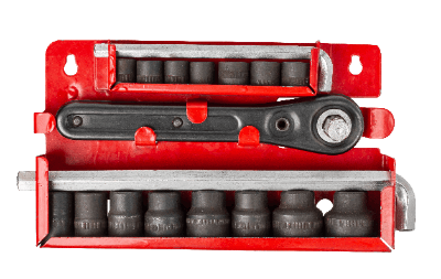
A socket wrench set generally includes a single handle and multiple interchangeable sockets. These sets vary in handle and head shapes, socket sizes, and other features, making it important to choose the right set for specific needs to avoid any issues.

Due to their versatility, socket wrench sets are commonly used for various tasks, including the maintenance of cars and motorcycles.

Uses of Socket Wrench Sets

Socket wrench handles are typically equipped with a ratchet mechanism, which allows force to be transmitted in only one direction. This feature makes it easy to switch the rotation direction, offering excellent operability. Socket wrench sets, with their array of sockets, are adaptable to a wide range of work scenarios and are therefore useful for a variety of applications, from automotive maintenance to home DIY projects.

How to Choose a Socket Wrench Set

When selecting a socket wrench set, consider the following points:

  • The thickness of the Wrench: Common sizes include 1/4-inch, 3/8-inch, and 1/2-inch, with the 1/4-inch size being the most widely used. The 1/4-inch wrench is suitable for holes smaller than 14mm, which encompasses most applications.
  • Head Shape: Round heads are ideal for tight spaces, while rectangular heads, with fewer ratchet gears, are easier to use in terms of switching rotation and determining direction.
  • Wrench Shape: Hexagonal wrenches are less likely to slip and are better for long-term use without damaging bolts, while dodecagonal wrenches fit bolts more easily, making them suitable for areas with limited visibility.
  • Handle Shape: Various handle shapes include ratchet handles, offset handles, and spinner handles. Ratchet handles are user-friendly and recommended for first-time buyers. Offset handles are slender and ideal for narrow spaces. Spinner handles have a pin at the end, allowing for insertion in tight spaces and the application of strong force.
カテゴリー
category_usa

Gear Puller

What Is a Gear Puller?

A gear puller is a specialized tool designed for removing gears that are assembled on equipment or machinery. It employs the force of a screw mechanism to pull off gears, particularly those that are difficult to detach manually due to rust or deformation.

Gear pullers are equipped with two or three-jaw claws for hooking onto gears. Three-jaw claws offer more stability in gripping. They are also used for removing timing pulleys, which are belts placed on gears, in a process sometimes referred to as pulley removal.

How to Use a Gear Puller

To use a gear puller, first, hook the claws onto the gear’s outer periphery. Then, tighten the center bolt until it contacts the shaft where the gear is assembled. While ensuring the center bolt and claws remain in place, tighten the hexagonal part using a wrench. This action pulls the gear until it loosens enough to be removed by hand. For wider gears, the claws’ length can be adjusted to fit larger diameters by changing the support point hole.

Caution is advised when removing tightly secured gears, as there is a risk of the gear flying off unexpectedly.

How to Choose a Gear Puller

When choosing a gear puller, consider the size of the gear to be removed. Larger targets require larger gear pullers and vice versa. Gear pullers can also be used for removing timing pulleys and bearings, with larger pullers often needed for timing pulleys. The size of a gear puller usually corresponds to the overall body size, but some models have longer claws while maintaining a standard body size.

The number of claws is another important factor. Two-jaw and three-jaw types are common, with three-jaw types offering more stability due to their three-point grip. However, more claws typically mean a higher price. Additionally, for bearing removal, a bearing puller could be a viable alternative.

カテゴリー
category_usa

Hydroforming

What Is Hydroforming?

Hydroforming is a process used to remove the insulation coating from bundled enamel wires (such as Litz wires, lead wires, magnet wires, etc.) and crimp them together for use in electronic devices. This method is essential for dealing with copper enamel-coated wires, which often have loose tips that need to be consolidated into a cohesive unit.

To break the insulation coating on these wires, methods such as chemical removal or heating dissolution are employed. Hydroforming utilizes the principle of resistance welding, passing welding current to generate heat that melts the insulation film under pressure. This process integrates the wire tips by welding them together.

After integration, the tip is clamped from the top and bottom to apply uniform pressure, ensuring a tightly bonded state. A secondary process, resistance soldering, can also be performed on the tip for heat crimping.

Types of Hydroforming

Hydroforming comes in various types, each suited to specific applications:

  • High-capacity inverter welding: Ideal for joining bundled magnet wires in motor coils and similar applications. It removes the enamel coating through electrical conduction and pressure, allowing for automation in tasks like hydroforming coils with multiple magnet wires and U-shaped terminals.
  • Hydroforming using inverter resistance welding: Offers high-precision control for both the upper and lower positions. The process stops electrical conduction at preset finishing dimensions, ensuring precise dimensional accuracy. This method is particularly effective for joining crimping terminals with numerous enamel wires.
カテゴリー
category_usa

Surface Analysis

What Is Surface Analysis?

Surface analysis is a technique that involves irradiating the surface of a target material with electron beams, X-rays, ions, or similar excitatory sources. This method detects the electrons, ions, or other particles emitted from the irradiated site to reveal the sample’s state at the molecular and atomic levels. It is particularly useful for analyzing chemical states and elemental compositions of substances that may be challenging to analyze by other methods.

Uses of Surface Analysis

Surface analysis applies to a wide range of materials, including organic substances, semiconductors, and inorganic materials. Specific methods like XPS (X-ray Photoelectron Spectroscopy), TOF-SIMS (Time of Flight Secondary Ion Mass Spectrometry), and AES (Auger Electron Spectroscopy) are employed for various analytical purposes, such as analyzing contaminants, determining molecular weights, and conducting qualitative and semi-quantitative element analyses.

Principles of Surface Analysis

Surface analysis operates on the principle that when an excitatory source is applied to the sample surface, it alters the energy state of surface atoms, causing the emission of particles like electrons and ions. Analyzing these emitted particles can clarify the sample surface’s state and structure. The depth of analysis and the types of particles emitted depend on the excitatory source and the analysis method used.

Types of Surface Analysis

Various methods are available depending on the depth and nature of the sample surface analysis required:

  • XPS (X-ray Photoelectron Spectroscopy): Also known as ESCA, this method uses X-rays to irradiate the sample surface, emitting photoelectrons whose energy spectrum reveals the elemental composition and bonding state of the surface.
  • TOF-SIMS (Time of Flight Secondary Ion Mass Spectrometry): This method involves irradiating the sample surface with an ion beam, and analyzing the emitted ions (secondary ions) to obtain elemental composition information and chemical structure details with high accuracy.
  • AES (Auger Electron Spectroscopy): This technique uses an electron beam to irradiate the sample surface, emitting “Auger electrons” whose unique energies allow for elemental analysis.
カテゴリー
category_usa

Surface Treatment

What Is Surface Treatment?

Surface Treatment

Surface treatment includes a range of mechanical, chemical, and physical processing methods applied to the surface of workpieces for specific objectives.

Purposes of Surface Treatment

The primary purposes of surface treatment are as a preparatory step for subsequent machining and to enhance the workpiece’s value. This includes improving adhesion, mechanical strength, oxidation resistance, and insulation, as well as enhancing aesthetic appeal and gloss.

Uses of Surface Treatment

Various surface treatment techniques like polishing, etching, electroplating, vapor deposition, molten coating, diffusion, coating, and anodizing are used based on the material and desired outcome.

  • Surface Polishing: Buff and barrel polishing for glossy finishes and surface smoothing.
  • Etching: Used for degreasing and removing grease and oxide films before plating.
  • Electroplating: Applied to eyeglass frames, household appliance frames, and mechanical components.
  • Vapor Deposition: Used for forming thin metal films in semiconductor manufacturing.
  • Molten Coating: Includes hot-dip galvanizing and thermal spraying for various industrial applications.
  • Diffusion: Employed for creating alloy layers on iron and steel surfaces and in semiconductor manufacturing.
  • Coating: Applying protective layers like paint or resin to prevent dirt, scratches, and oxidation.
  • Surface Cleaning: Removing foreign substances and dirt, often as a pre-processing step.
  • Anodizing: Enhancing wear and corrosion resistance, insulation properties, and thermal conductivity.

Principles of Surface Treatment

The principles of surface treatment vary depending on the method, ranging from mechanical polishing to chemical etching, electroplating, vapor deposition, surface cleaning, molten coating, diffusion, coating, and anodizing. Each technique has its specific mechanism and applications, catering to different industrial needs.

カテゴリー
category_usa

Wire Cutting

What Is Wire Cutting?

Wire cutting, formally recognized as wire electrical discharge (Wire EDM) machining, is a method that cuts materials by melting them with high-temperature discharge between a wire and the workpiece. This technique applies to a broad range of conductive metals, from thin aluminum sheets to super-hard materials up to 50mm thick.

Noted for its high precision, wire cutting is ideal for intricate shaping and manufacturing precision components.

Uses of Wire Cutting

Wire cutting is known for its high-precision processing capabilities across various conductive materials, regardless of their hardness. It is used for thin metal sheets and super-hard materials such as hardened steel, carbide, stainless steel, brass, aluminum, Inconel, dies, and polycrystalline diamond.

Principle of Wire Cutting

In wire cutting, a processing tank filled with fluid like pure water or oil contains the workpiece. A thin wire, typically brass or tungsten, acts as the electrode. The technique involves repeated discharge explosions between the wire and workpiece, facilitated by pulse current, to melt and cut the material without physical contact.

The wire, usually brass with a diameter of 0.1 to 0.3mm, is chosen for its excellent conductivity. The temperature during processing can reach 6,000 to 7,000°C. A cooling system in the tank maintains constant water temperature to prevent thermal expansion and deformation of the material.

Types of Wire Cutting

Wire cutting varies based on the cooling method for the wire electrode and workpiece, with common types including jet flow, submerged water, and oil tank submersion wire cutting.

Other Information on Wire Cutting

Wire cutting offers numerous advantages, such as high-precision micro-machining, the ability to process hard-to-cut materials, clean finish, non-contact processing, and no need for cutting tools. However, it also has drawbacks like slow processing speed, limitations on processing bottomed workpieces, the requirement for material conductivity, and the inability to process horizontally.

カテゴリー
category_usa

Microfabrication

What Is Microfabrication?

Microfabrication

Microfabrication is a process that operates on the micron scale (1 mm to 0.001 mm), bridging the gap between conventional machining and nanotechnology. It focuses on micron-order precision, often employing laser processing for its ability to focus on extremely small areas with adjustable parameters like laser output and pulse width.

Uses of Microfabrication

Microfabrication is utilized in various fields, particularly in creating intricate components from materials like metals, resins, and engineering plastics. Its applications span the medical, aerospace, semiconductor, and electronics industries, among others.

  • Titanium Materials: In the medical field, used for implants and dental components, and in aerospace for part machining.
  • Aluminum Materials: In LCDs for thin-wall processing and semiconductor manufacturing for precision component fabrication.
  • Stainless Steel Materials: For producing fine mechanical parts in electron beam equipment, medical devices, and semiconductor moldings.
  • Engineering Plastic Materials: In semiconductor production for manufacturing and inspection jigs, and IC inspection for connector processing.
  • Machinable Ceramics: In LSI chip wafer inspection for fabricating probe cards.

Structure of Microfabrication

Laser microfabrication employs short-pulse lasers like nanosecond, femtosecond, and picosecond lasers. These lasers enable microscopic fabrication while minimizing thermal damage through a process called “ablation.”

Types of Microfabrication

Microfabrication methods vary, with ultra-precision microfabrication using NC machine tools being a prominent example. This includes micro-hole machining, microgroove machining, precision microfabrication, complex surface machining, and mirror finish machining on various materials.

Choosing Microfabrication Techniques

Selecting appropriate microfabrication techniques involves considering the precision of tools and equipment. This includes selecting high-precision machining tools, maintaining a stable temperature environment to account for material shrinkage, implementing vibration countermeasures, and using high-performance CNC image measuring instruments for accurate quality assurance.

カテゴリー
category_usa

Wind Tunnel Test

What Is a Wind Tunnel Test?

Wind Tunnel Test

A wind tunnel test is a process where scaled-down models are exposed to the airflow generated by blowers to analyze wind flow patterns and evaluate wind pressure resistance. This test is primarily utilized in the design phase of structures that are significantly affected by wind, such as skyscrapers and large-scale constructions.

The objective of this test is to assess factors like wind resistance, aeroacoustics, and habitability under strong wind conditions. It plays a vital role in ensuring the safety and comfort of structures where wind impact is a critical consideration. These evaluations are essential in optimizing the design to withstand wind forces, reduce noise caused by wind, and ensure the building remains habitable and safe under various wind conditions.

Wind tunnel tests are also widely used in the automotive industry to investigate the aerodynamic resistance of vehicles. By studying how air flows around a vehicle, designers can enhance its efficiency, stability, and fuel consumption.