カテゴリー
category_usa

Digital Signage

What Is a Digital Signage?

Digital Signages

Digital Signage is a system or platform that utilizes digital media technology to display information and advertisements.

Typically employing digital display devices such as LCD screens or projectors, Digital Signage showcases multimedia content like images and videos. Due to its ability to update content in real-time, Digital Signage can promptly display the latest information and promotions. This allows for quick responses to special events or sudden changes, reducing printing costs and labor.

However, as a digital device, Digital Signage may encounter technical issues or malfunctions such as display failures or software crashes. Therefore, proper maintenance and management through suitable technology are essential.

Uses of Digital Signage

The primary uses of Digital Signage include:

1. Retail Industry

In the retail sector, Digital Signage is employed to enhance information communication and customer engagement within stores. It efficiently displays real-time promotional information and special sale details, emphasizing the attractiveness of products. Additionally, it allows instant updates on pricing and inventory information, providing customers with the latest details.

2. Food and Beverage Industry

Digital menu boards in restaurants and cafes assist in presenting menu items and prices to customers in a clear and understandable manner. They are effective in promoting daily specials and sales promotions. Furthermore, the introduction of digital ordering systems contributes to streamlining the ordering process and improving service.

3. Public Transportation

In stations and airports, Digital Signage provides travelers with information on train and flight departure times and operational details. Bus stops can display bus arrival schedules and route information, offering convenience to users.

4. Education

In educational institutions, Digital Signage is used to convey important information within the campus. This includes providing students and faculty with schedules and campus event details and enhancing communication and information sharing.

Principle of Digital Signage

The principle of Digital Signage is based on combining digital technology and display technology to present information and content. The process involves the creation and management of content, which includes various media elements such as text, videos, and animations. Content is often created and edited using computer software and content management systems.

To display Digital Signage content, various display devices are used, including LCD screens, plasma displays, projectors, etc. These display devices are designed to provide high-resolution, clear images and videos that are easily readable even from a distance.

To transmit Digital Signage content to display devices, media players or Digital Signage players are commonly used. These hardware or software components play and transmit content to the display device. Some Digital Signage devices come with embedded media players.

How to Choose Digital Signage

Several crucial factors need consideration when choosing Digital Signage. Here are some selection elements:

1. Purpose

Clearly defining how Digital Signage will be used is crucial. Depending on specific purposes such as advertising or displaying schedules, choose the appropriate Digital Signage accordingly.

2. Environment

Select devices that suit the installation location and environment. Consider factors like whether the device will be placed indoors or outdoors, in high-temperature or high-humidity areas. It’s important to contemplate durability and waterproofing, and generally, higher durability often correlates with a higher cost.

3. Display Device

Given the variety of display devices like LCD screens, LED displays, projectors, etc., evaluate factors such as resolution, size, and visibility to choose a device that best fits the intended use.

4. Network

Digital Signage commonly connects to a network for real-time content updates and remote management. Consider whether internet connectivity is required or if a private network will be established. Depending on the network structure, choose suitable display devices and equipment.
カテゴリー
category_usa

Guide Bushing

What Is a Guide Bushing?

A guide bushing is a fixture used in automatic lathes with spindle movement for precision component machining. Its purpose is to precisely hold the workpiece during processing.

Automatic lathes are machines that rotate the spindle gripping the material with a chuck while performing cutting operations with blades. There are two types of automatic lathes: those with a spindle that moves in the Z-direction while bringing the workpiece into contact with the blade for cutting (spindle-moving type) and those with a fixed spindle while moving the blade for cutting (spindle-fixed type).

In both types of automatic lathes, when the distance from the chuck, holding the material, to the blade becomes long, deflection and vibration increase, making precise machining difficult. Therefore, in spindle-moving automatic lathes, the guide bushing is used near the cutting point to hold the material, enabling higher precision machining. This fixture is referred to as the guide bushing.

Uses of Guide Bushing

The guide bushing is used in spindle-moving automatic lathes to accurately hold the material, enhancing the precision of cutting operations. However, while it is an essential fixture for spindle-moving automatic lathes, there are cases where it is not used.

Spindle-moving automatic lathes are suitable for machining thin and long precision parts. Originating in Switzerland and known as Swiss-type automatic lathes, these machines were developed for machining precision parts for watches. Guide bushings prove useful when dealing with product shapes that result in long distances between the chuck and the part where the blade makes contact, or when the material itself is thin and prone to deflection. The application of guide bushings extends beyond watch components to various industries, including medical devices, aerospace parts, and automotive components.

Principle of Guide Bushing

The guide bushing is fundamentally cylindrical and is attached just before machining in a Swiss-type automatic lathe. In addition to cylindrical guide bushings, there are square and hexagonal variations. The mainstream materials are steel with attached carbide, although some feature ceramics or cermet.

Attachment methods include a taper at the end of the guide bushing for press-fitting or a threaded part for screwing. Some guide bushings have a flange with screw holes, allowing them to be securely attached to the main body using screws.

Guide bushings play a role in supporting materials in extremely narrow gaps during installation, allowing the material to rotate while minimizing deflection and vibration. In addition, they are designed to enable the material to move in and out in the Z-axis direction along with the spindle’s Z-axis movement. Consequently, machines that synchronize the rotation of the guide bushing with the spindle’s rotation have become prevalent.

Some automatic lathes allow machining without using guide bushings, providing guide bushing detachable models. While guide bushing mechanisms inevitably result in the waste of material at the end of the spindle collet chuck to the guide bushing, guide bushing-less mechanisms allow more economical utilization of the material until the end.

How to Choose Guide Bushing

The shape, size, and attachment method of usable guide bushings vary by automatic lathe manufacturer. When selecting guide bushings, the first step is to choose from products compatible with the automatic lathe used in-house.

Choosing a guide bushing with a smaller difference between the material’s outer diameter and the guide bushing’s inner diameter makes it easier to prevent deflection and vibration, enhancing performance.

Moreover, considering the surface condition of the material, it is crucial to select the material and surface treatment of the guide bushing appropriately. For instance, when machining hard materials like stainless steel or titanium alloys, opting for a high-wear-resistant guide bushing, such as one with attached carbide, is advisable.

カテゴリー
category_usa

Special Tool

What Is a Special Tool?

Special tools are tools with specific materials and performance characteristics compared to commercially available general cutting tools.

They are used to process parts with complex shapes and dimensions that are difficult to achieve with general-purpose tools. These tools are specially designed with materials and shapes suitable for specific applications and environmental conditions, aiming to provide high efficiency and precision. Each tool possesses characteristics suitable for specific materials and applications, offering high wear resistance, heat resistance, durability, and precision. Therefore, special tools are crucial for achieving high-quality processing tailored to specific workpieces or conditions.

Uses of Special Tools

Here are examples of general applications for special tools:

  • Machining of hard metals such as stainless steel, hard aluminum alloys, and superhard alloys.
  • Processing non-metallic hard materials like ceramics, glass, and gemstones.
  • Grinding and drilling of other hard materials.
  • Ultra-precision processing and high-speed cutting.
  • CNC turning and milling operations.
  • Manufacturing precise optical components and semiconductor devices.
  • Shaping and drilling of metal parts.
  • Processing complex shapes and grooves.
  • Metal cutting at high temperatures.
  • Common metal processing, especially cutting, drilling, and milling of common steel.
  • Manufacturing of machine parts and tools.
  • Reducing tool replacement frequency in automated lines for labor savings.

Special tools find applications in various industries, including aerospace, automotive manufacturing, medical device production, gemstone processing, and precision machinery manufacturing.

Principles of Special Tools

The principle of cutting tools is based on the idea that when a hard material comes into contact with a softer material and force is applied to move either material, the surface of the softer material peels off. Therefore, the principle of cutting tools involves using a material harder than the material being cut.

In recent years, as the hardness of materials to be cut has increased, the materials used for tools have also become harder. With the diversification of cutting purposes and materials, there are various types of cutting tools. Some of the main materials include cemented carbide, high-speed tool steel (HSS), diamond, polycrystalline diamond (PCD), cubic boron nitride (CBN), ceramics, and cermet. Considering the size, shape, and purpose of the tool, there is an extremely diverse range of types.

The manufacturing methods of special tools vary depending on the type, application, and design of the tool. Generally, materials such as cemented carbide and tool steel are selected for their hardness and shape. Depending on the size, tools can be manufactured as solid (the entire tool is made of high-hardness material) or with only the cutting edge made of high-hardness material. Additionally, advanced materials like diamond and CBN may be attached or coated through methods such as spattering, chemical vapor deposition (CVD), or physical vapor deposition (PVD).

It is important to note that diamond tools experience minimal wear during cutting. This allows diamond tools to maintain high performance over an extended period. Even in situations where other materials would wear out quickly, diamond tools effectively continue cutting materials. They also have excellent thermal conductivity, rapidly transferring heat from the tool’s edge to cool the cutting surface. This characteristic prevents the accumulation of heat during material processing, extending the tool’s lifespan.

However, due to the nature of diamond being a cluster of carbon atoms, it is unsuitable for cutting steel materials. When cutting steel materials, carbon atoms are absorbed by the steel as the cutting edge temperature rises, leading to edge wear or damage. Furthermore, diamond tools enable highly precise cutting and grinding, providing a high-quality finish. This is particularly crucial for applications requiring precise workpieces and high-precision dimensions.

Types of Special Tools

Below are the main types of special tools.

These special cutting tools with unique materials operate based on different principles according to each material’s characteristics, providing high efficiency and durability. Understanding the principles of cutting tools and selecting and using them appropriately are key to achieving high-quality and high-efficiency machining operations. There are various shapes, such as drills, reamers, end mills, fly cutters, side cutters, metal saws, countersinks, T-slot cutters, trepanning tools, recessing tools, boring tools, taps, dies, hobs, broaches, punches, and bits, based on one or a combination of the materials listed below.

1. Cemented Carbide Cutting Tools

Cemented carbide refers to an alloy composed of hard metal carbides and iron-based metals. A typical composition of cemented carbide is made by mixing powder of rare metals called tungsten carbide (WC) and cobalt (Co), sintering them at around 1,400°C.

It has characteristics such as higher hardness, elastic modulus, compressive strength, thermal conductivity, and specific gravity, as well as a lower coefficient of thermal expansion compared to tool steels like high-speed tool steel (HSS). Due to these characteristics, cemented carbide tools have a longer lifespan, maintaining sharpness without frequent replacements. The cutting edge is less prone to wear, providing stable performance even at high temperatures. Cemented carbide has become a common tool material, replacing the previously mainstream high-speed tool steel (HSS).

2. Diamond Cutting Tools

Diamond cutting tools, made from extremely hard natural or synthetic diamonds, have diamond particles or sintered diamond bodies attached to the cutting edges. They are used for cutting hard materials such as cemented carbide. Diamonds are highly resistant to wear and have high thermal conductivity, making them suitable for working at high temperatures. They are used for cutting, grinding, and drilling hard materials like aluminum, ceramics, glass, gemstones, and others.

3. Ceramic Cutting Tools

Ceramic materials can withstand high temperatures and have high hardness, making them suitable for cutting operations at elevated temperatures. Ceramic cutting tools provide thermally stable performance. Although ceramics are brittle and can chip during cutting, recent improvements have addressed these issues. They are primarily used for metal cutting at high temperatures (dry or semi-dry processing), processing superhard materials, and ultra-precision machining.

4. Steel Cutting Tools

Steel cutting tools, typically made from high-speed tool steel (HSS), enhance hardness and wear resistance through alloying or heat treatment. The cutting tools made from steel generally follow the normal principles of metal cutting but leverage the specific characteristics of certain types of steel. HSS tools, with higher impact strength and fracture toughness compared to cemented carbide, can outperform carbide tools in specific machining operations when coated.

These are some of the common types of special cutting tools, each optimized for different applications and materials. The selection of cutting tools is based on the material being processed, the machining process, desired precision, and working conditions. Special cutting tools with unique materials are designed to meet the specific needs of machining, possessing characteristics such as high wear resistance, heat resistance, and hardness.

カテゴリー
category_usa

Diamond Tool

What Is a Diamond Tool?

Diamond Tools refer to tools and cutting instruments manufactured using extremely hard natural diamonds or synthetic diamonds as materials.

Diamond (single crystal) is utilized in cutting tools for metal processing, grinding wheels, wire saws, and polishing due to its high hardness. While Diamond Tools (single crystal) can achieve a very sharp cutting edge with a long lifespan and high performance, their complex shaping is challenging, and their manufacturing cost is high, making them relatively expensive. Consequently, they are employed in applications that demand very high precision and durability.

However, diamonds possess cleavage properties along crystal planes, and their hardness may not be consistent. For processing complex shapes, synthetic polycrystalline diamond (PCD) is commonly used. Being polycrystalline, PCD is an assembly of single crystals facing various directions, providing strength from all angles and exhibiting resistance to cleavage.

Uses of Diamond Tools

The primary applications of Diamond Tools include:

1. Machining

PCD tools are preferred over carbide and ceramic tools in the production of high-quality parts and the machining of difficult-to-cut materials. Due to their durability and performance, they are widely adopted in various industries, including automotive and aerospace, for processing materials such as aluminum, superalloys, CFRP, and other highly resistant materials.

2. Construction Industry

Diamond core bits and diamond wire saws are used to cut construction materials such as concrete, asphalt, and stone. They play a crucial role in drilling and cutting operations on construction sites.

3. Stone Industry

Diamond tools are employed in cutting, polishing, and carving natural and synthetic stones. Artists and stonemasons use them to realize artistic projects.

4. Electronics Industry

In the electronics industry, diamond tools are used for precision work such as cutting and polishing silicon wafers and semiconductor manufacturing processes. The hardness of diamonds proves valuable in this field where high precision is required.

5. Gemstone Processing

In addition to being valued as gemstones, diamonds are used as tools to cut, polish, and carve other gemstones. They find extensive use in the jewelry industry.

6. Medical Field

Diamond-bladed scalpels and drills are used in surgeries, such as neurosurgery and dental procedures. Diamond blades are precise and extremely sharp.

7. Research and Science

Diamonds are used in specialized scientific equipment like high-pressure high-temperature experiments and diamond anvil cells.

Principle of Diamond Tools

The principle of Diamond Tools is based on utilizing the extreme hardness and wear resistance of diamonds when cutting, shaping, or removing other materials.

Diamond is one of the hardest substances on Earth, having a hardness of 10 on the Mohs hardness scale, indicating its significantly greater hardness compared to most other materials. Consequently, diamond provides wear resistance when cutting or shaping various materials.

Diamonds used in tools are typically attached to a metal or ceramic substrate. They are fixed to these substrates, functioning as the cutting edge of the tool. Additionally, techniques such as sputtering, chemical vapor deposition (CVD), and physical vapor deposition (PVD) are employed to coat surfaces with a layer of diamond by depositing carbon atoms, enhancing the tool’s hardness.

Importantly, diamonds experience minimal wear during cutting operations. This attribute allows Diamond Tools to maintain high performance over extended periods. While other materials would quickly wear out, Diamond Tools effectively continues cutting materials. Furthermore, diamonds exhibit excellent thermal conductivity. This property ensures that heat generated during cutting is quickly dissipated, preventing the accumulation of heat and extending the tool’s lifespan.

However, due to the nature of diamonds as clusters of carbon atoms, they are not suitable for cutting iron-based steel. When processing iron-based steel, the absorption of carbon atoms into the iron at elevated blade temperatures can lead to edge wear or damage. Additionally, Diamond Tools excels in providing precise cutting and polishing, delivering high-quality finishes. This is particularly crucial in applications requiring precise workmanship or high-dimensional accuracy.

Types of Diamond Tools

The main types of Diamond Tools include:

1. Diamond Cutting Tools

Manufactured by shaping single crystal diamonds or polycrystalline diamonds onto cutting tools, such as drills, reamers, end mills, and bits made of materials like cemented carbide and tool steel. These tools are versatile, allowing various machining operations like drilling, grooving, milling, and cutting.

2. Diamond Cutting Wheels

Produced with different bonding materials such as metal bonds or resin bonds, these wheels are used to cut hard materials like metal, ceramics, glass, and stone. They find widespread use in the construction, manufacturing, and processing industries.

3. Diamond Grinding Wheels

These grinding wheels have diamond particles fixed to the surface and are used to polish metal and hard materials. They are utilized in metalworking, gemstone processing, and precision engineering.

4. Diamond Wire Saws

Suitable for cutting stone and concrete, these wire saws are employed in construction, stone processing, and environmental surveys.

5. Diamond Core Bits

Used for drilling holes in materials like concrete, asphalt, and stone. They are common in construction and geotechnical investigations.

6. Diamond Carving Tools

Used by artists and craftsmen to carve materials such as stone, wood, glass, and metal, contributing to the creation of artistic projects.

7. Diamond Drill Bits

Utilized for drilling holes in concrete and stone, these bits are commonly used in construction projects.

8. Diamond Cutters

Diamond cutters are employed in various cutting tools, ranging from surgical scalpels to glass cutters. Diamond abrasive stones and papers with diamond abrasives are used for tool sharpening and polishing tasks.

These represent some of the main types of Diamond Tools, each suited for specific applications, including cutting, machining, polishing, carving, and more, across various industries.

カテゴリー
category_usa

Turnbuckle Brace

What Is a Turnbuckle Brace?

A Turnbuckle Brace is a reinforcing material used in the primary structural components of architectural structures.

It is employed to enhance the strength and durability of buildings and structures against external forces such as earthquakes and wind. Typically, it consists of a long rod made of steel and is frequently attached to the structure of a building. The adjustable length of the brace allows for flexibility in building design. By adjusting the length of the brace, it becomes possible to efficiently tune the vibrational characteristics and seismic resistance of a building, making it applicable to various architectural structures. Moreover, Turnbuckle Braces are often available as prefabricated components, contributing to the efficiency of assembly and installation on construction sites.

However, it is crucial to note that accurate design and construction are paramount for this critical component. If the length and installation angles of the brace are not appropriate, the expected enhancement in seismic resistance may not be achieved.

Uses of Turnbuckle Brace

Turnbuckle Braces find applications in various primary structural components of architectural structures. The main uses are outlined below.

1. Small to Medium-Sized Steel Frame Buildings

In the context of recent seismic events, ensuring the overall resilience of steel-framed buildings has become increasingly crucial. Specifically, in steel-framed buildings equipped with Turnbuckle Braces conforming to JIS standards, these braces play a significant role in ensuring the overall resilience of the structure. Consequently, they are widely used to enhance seismic resistance in small to medium-sized steel-framed buildings.

2. Public Facilities

To enhance the seismic resistance of older structures like school buildings, reinforcement with Turnbuckle Braces may be employed. This approach allows for maintaining historical value while ensuring safety. Additionally, in hospitals, where vibrations can impact the normal operation of equipment and surgeries, Turnbuckle Braces control vibrations, securing the proper functionality of facilities. They are also used in tall communication towers to control vibrations and prevent collapse or damage.

3. Bridge Construction

Elevated bridges are structures susceptible to wind effects. Turnbuckle Braces are used to control vibrations caused by wind, maintaining stability. Pedestrian bridges and highway overpasses, being prone to wind effects, often utilize Turnbuckle Braces for wind reinforcement.

4. Historical Structures

Some historical structures may not meet modern seismic standards. Turnbuckle Braces are often chosen as a reinforcement method to protect these buildings.

Principle of Turnbuckle Brace

A Turnbuckle Brace is fundamentally a reinforcing element made of steel with an adjustable length. It is commonly manufactured using steel. It consists of components such as round steel bolts, turnbuckle bodies, and fasteners.

1. Round Steel Bolt

The round steel bolt is a crucial component of the Turnbuckle Brace, featuring a male screw at its tip. It is a diagonally arranged rod steel designed to enhance the resistance of the building against external forces like earthquakes and wind.

2. Turnbuckle Body

The turnbuckle body is a component used to fine-tune the length of the Turnbuckle Brace. Typically featuring female threads at both ends, it is combined with round steel bolts. Tightening the turnbuckle body shortens the overall length of the Turnbuckle Brace while loosening it allows for extension.

To connect the Turnbuckle Brace with the structural elements of the building, fasteners such as bolts are used. These fasteners ensure the overall stability of the Turnbuckle Brace and enhance durability against external forces.

How to Choose Turnbuckle Brace

When selecting Turnbuckle Braces, consideration should primarily be given to factors such as:

1. Short-Term Allowable Load Capacity

Turnbuckle Braces need to withstand short-duration external forces like earthquakes and wind. Confirming the short-term allowable load capacity of the brace during the design phase is essential for ensuring safety against temporary external forces.

2. Long-Term Allowable Load Capacity

Considering the capacity to withstand loads and deformations over an extended period is crucial. The long-term allowable load capacity of the brace indicates the required strength to resist external forces. Material selection and determination of the brace’s cross-sectional area are crucial in this regard.

3. Tensile Strength

Turnbuckle Braces are primarily designed to withstand tensile stress. The tensile strength of the brace indicates the required strength to resist external forces. Material selection and determination of the brace’s cross-sectional area are crucial in this regard.

4. End Shape

The shape of end attachments influences the stability of brace installation and connection. Accurate design and the use of appropriate fasteners are vital for firmly connecting the Turnbuckle Brace and the structural elements. Common shapes include plate-type and hook-type attachments.

カテゴリー
category_usa

Experimental Design Software

What Is an Experimental Design Software?

Experimental Design Software, also known as DOE (Design of Experiments) software, is a tool designed to assist in the design and analysis of experiments based on the field of experimental design, which is a branch of applied statistics.

Experimental design, or Design of Experiments (DOE), is considered a field of applied statistics. It aims to design efficient experimental methods for situations where multiple factors influence each other, allowing for the mathematical analysis of results. Developed based on the ideas of the British statistician R.A. Fisher, it is built upon three principles known as Fisher’s Three Principles: local control, replication, and randomization.

While conducting experiments based on experimental design can enhance efficiency and lead to meaningful conclusions, it requires specialized knowledge and experience due to its complex procedures. Experimental Design Software facilitates the process by providing templates for these procedures and automating the analysis, making experimental design and analysis more accessible.

Uses of Experimental Design Software

Experimental design finds applications in various fields such as manufacturing, healthcare, agriculture, and marketing, and the software designed for it is widely used in these areas.

1. Manufacturing

In manufacturing, Experimental Design Software is employed to enhance product quality and productivity. By varying parameters related to quality, such as temperature management and reaction times, manufacturers evaluate the strength and durability of produced products or materials. This process aims to find optimal manufacturing conditions considering factors like yield and production costs.

2. Healthcare

In the healthcare sector, Experimental Design Software is utilized for the development of new drugs and the optimization of treatment methods. It contributes to the efficiency of tasks related to evaluating the effectiveness and safety of drugs or optimizing treatment methods.

3. Agriculture

Agriculture employs experimental design to increase crop yield and improve quality. By varying factors such as the use of fertilizers and pesticides, observations are made on changes in crop yield, size, taste, etc. This helps in achieving a better harvest.

4. Marketing

Experimental Design Software plays a role in devising marketing strategies. For instance, efficiently increasing awareness of new products or services, helps determine the type of advertisement suitable for each target group by varying target demographics.

Principles of Experimental Design Software

Experimental design is based on Fisher’s Three Principles: local control, replication, and randomization. Designing experiments and conducting them based on these principles allows for obtaining correct data more quickly.

  1. Principle of Local Control
    When there are numerous factors influencing the experiment, all factors except the one being investigated are kept as constant as possible.
  2. Principle of Replication
    To eliminate the influence of random errors in each experiment, repetitions under the same conditions are performed.
  3. Principle of Randomization
    When extracting data, statistical methods are used to randomly select samples.

Experimental Design Software is designed with functionalities that support the design and analysis of experiments based on real-world scenarios in manufacturing, healthcare, and other fields. Therefore, it allows for concluding experiments with fewer trial runs, quantitatively evaluating effects, understanding interactions between factors affecting experiments, and modeling experiments to find optimal solutions.

How to Choose Experimental Design Software

Experimental design comes in various types, including screening design, factorial design, response surface design, Taguchi design, and mixture design. Choosing the right software involves considering the specific type of experimental design needed.

Different software types support different design types, and there are variations in features such as validation tools, graphical tools, and numerical optimization tools. Some software may offer a trial of certain features for free.

While Experimental Design Software is intended to simplify the design and analysis of experiments, it can be challenging to handle without expertise in experimental design. Therefore, it is crucial to read books on experimental design, attend relevant seminars, and gain a deep understanding before making a selection.

カテゴリー
category_usa

Process Analytical Technology (PAT)

What Is a Process Analytical Technology (PAT)?

PAT, an abbreviation for Process Analytical Technology, is a technology employed for monitoring and analyzing products during the manufacturing process to enhance product quality.

To ensure product quality, quality inspections are typically carried out before shipment. However, conducting inspections only at the final stages of the manufacturing process can lead to inefficiencies, as defective materials, time, and resources may be wasted when defects are discovered.

Therefore, by implementing intermediate inspections for each manufacturing process, PAT allows for the early detection and timely addressing of manufacturing defects, enabling efficient production.

PAT serves as a quality management technique utilized in the manufacturing of pharmaceuticals, chemicals, and food products. At each stage of the manufacturing process, various analytical techniques are employed to monitor the quality of intermediate products in real time. In the event of abnormal quality, PAT immediately issues warnings and prompts corrective actions.

Uses of PAT

PAT is primarily utilized in the manufacturing processes of products such as powders, liquids, and gases. The system monitors the physical, chemical, or biological properties of intermediate products using sensing technologies.

Additionally, PAT systems continuously monitor the values obtained during monitoring. If values exceeding normal parameters are observed, the system issues warnings to operators, prompting appropriate responses, or even automatically halting processes.

For example, in the pharmaceutical manufacturing process, PAT measures physical quantities such as temperature, pressure, and pH to predict the occurrence of defects. In food manufacturing processes, chemical measurements like color and viscosity are taken to predict the quality and detect any abnormalities in taste in the final product. In chemical manufacturing processes, measurements of composition and concentration are taken to evaluate product quality and assess the safety of subsequent processes.

Principles of PAT

PAT is particularly emphasized in the pharmaceutical manufacturing process within various manufacturing sectors.

PAT operates by coordinating three main functions: sensors that measure physical, chemical, or biological characteristics at each manufacturing process, analytical devices that analyze data obtained from sensors, and quality management functions that judge whether the product’s quality is maintained based on the analysis results.

By ensuring that PAT is continually implemented in real-time for each manufacturing process, any issues that arise can be promptly communicated to administrators, allowing for early action and preventing a decline in manufacturing yield.

For instance, when establishing temperature management for a reaction vessel used in a certain manufacturing process, data on the upper and lower limits of temperatures at which products can be manufactured properly are obtained. A management boundary is then set within a stricter range than this, and immediate action can be taken if the process exceeds this limit.

This proactive approach prevents defective products from flowing into subsequent processes.

Types of PAT

PAT is a technology used for quality management in manufacturing processes, and the measurement targets, measurement methods, and analysis methods vary. As long as it aligns with the concept of quality management technology, using various sensors and analytical methods qualifies as PAT.

However, industries with high demand, such as pharmaceutical manufacturing, have commercially available PAT analysis devices that combine specific sensors and analytical equipment to fulfill some of PAT’s functions.

For example, there are composition analysis devices that use in-situ spectroscopy or chromatography. These devices attach sensors to process equipment, allowing real-time analysis results to be obtained as the process progresses. Additionally, PAT analysis devices that utilize Near-Infrared Spectroscopy (NIR) or Raman Spectroscopy (Raman) are available for pharmaceutical development.

How to Choose PAT

PAT is a comprehensive method for quality management in manufacturing processes, combining various products and technologies. Therefore, the choice of PAT varies depending on the type of products and processes being manufactured.

In fields like pharmaceutical manufacturing, if PAT-related products applicable to the company’s manufacturing processes are identified, consulting with the manufacturer or distributor of those products is recommended. Some companies also conduct seminars related to PAT, and participating in such seminars can be effective.

カテゴリー
category_usa

Pressure Relief Valve

What Is a Pressure Relief Valve?

Pressure Relief Valves

A pressure relief valve, also known as a residual pressure exhaust valve, is a valve designed to effectively release the residual pressure within a fluid system.

Typically employed in systems such as pressure vessels and pipelines, this mechanical component addresses the concept of residual pressure, which generally refers to the presence of remaining pressure or hydraulic force. When there is residual pressure in a fluid system carrying liquids or gases, the fluid within the system may continue to flow. Releasing residual pressure is crucial, especially for maintenance-related safety considerations, as it can impact the safe handling of equipment.

The use of a pressure relief valve allows for the safe release of pressure within the system. Consequently, these valves are frequently adopted in facilities where safety is a top priority.

However, it is paramount for pressure relief valves to function correctly. In cases of blockage, failure to completely release residual pressure may occur, emphasizing the need for regular inspections and maintenance. Visualizing internal pressure alongside instruments such as pressure gauges enhances safety.

Uses of Pressure Relief Valve

Pressure relief valves serve as crucial devices used in various industrial sectors.

1. Steam Piping

Steam generated in boilers and heating systems is supplied at high pressure. Even after processes are halted, there is a possibility of excessive steam pressure remaining in the piping. When maintaining such piping, pressure relief valves are often employed to exhaust excess steam pressure, reducing the system pressure to atmospheric levels. This prevents damage to equipment and pipelines, ensuring operational safety.

2. Hydraulic Presses

In hydraulic units like hydraulic presses, hydraulic pressure may linger after the operation concludes. If piping is opened in this state, there is a risk of dangerous high-temperature oil injection. A pressure relief valve exhausts excess hydraulic pressure, restoring the system to a safe state.

3. Compressed Air Piping

In air pressure systems, when devices or actuators that were in operation come to a stop, air may remain within the equipment. This can lead to unexpected movements of the equipment that has supposedly stopped. Using a pressure relief valve allows for the safe venting of pressure within the equipment after operation, stabilizing system operation.

Principles of Pressure Relief Valve

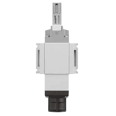
While pressure relief valves come in various types, many use a 3-port valve configuration. They typically consist of a valve body, handle, and valve element.

The valve body is commonly made of metal or alloys and is designed for attachment to piping via threading or flanges. It has a structure with one inlet port and two outlet ports.

The handle, attached to the valve body, is the component used to operate the valve element. In the case of electric or pneumatic operation, electromagnetic coils or cylinders may be attached. By manipulating the handle, the position of the valve element can be controlled, regulating the exhaust of fluid.

The valve element is the component that controls the movement of fluid. By contacting the seat on the valve body, it seals and prevents fluid leakage. The operation of the valve element determines whether the outlet ports are connected to the inlet port or if exhaust occurs.

How to Choose a Pressure Relief Valve

When choosing a pressure relief valve, several factors need to be considered.

1. Installation Pipe Diameter

The size of the pressure relief valve must match the inner diameter of the piping where it will be installed. Choosing a valve that fits the pipe diameter ensures proper flow rates and improves system efficiency.

2. Operating Pressure Range

For proper valve operation, it needs to withstand the maximum pressure. Exceeding the maximum operating pressure is hazardous, potentially causing equipment damage or forceful fluid leakage. The selected pressure relief valve should operate effectively within the maximum pressure range.

3. Material

Considering the type of fluid and its chemical characteristics, selecting the appropriate material is crucial. Corrosive fluids require materials with high corrosion resistance. Common materials include stainless steel, brass, and iron.

4. Manual or Automatic

The valve’s operating mode, manual or automatic, must be chosen. Manual operation involves human control to open and close the valve, while automatic operation uses electric, pneumatic, or hydraulic actuators for control.

5. Operating Temperature

The temperature of the fluid being handled dictates the proper selection of the valve. If the fluid temperature exceeds the allowable temperature, it may cause malfunction. Special attention is required, especially when dealing with high-temperature fluids like steam.

カテゴリー
category_usa

Flux Meter

What Is a Flux Meter?

A flux meter is a device designed to measure the magnetic flux in an electromagnetic field.

Magnetic flux is represented by the number of magnetic field lines passing through a certain area, and it is a crucial indicator for understanding the strength and variations of electromagnetic fields. Flux meters are widely used in applications such as monitoring changes in the Earth’s magnetic field for geophysical measurements and industrial purposes. Due to their high sensitivity and accuracy, they can detect extremely small changes in magnetic flux. Additionally, they allow for non-intrusive measurements as physical contact with the measurement target is not required.

However, periodic calibration may be necessary to obtain accurate measurement results. The performance of the measurement device and sensing coils may change over time, requiring attention to maintain reliability.

Uses of Flux Meter

Flux meters have a wide range of applications in various fields.

1. Geomagnetic Measurements

Flux meters are used to monitor variations in the geomagnetic field generated by the dynamo effect within the Earth. Changes in the Earth’s magnetic field are related to internal processes, making them useful for predicting and researching earthquakes and volcanic activities. Installed in geomagnetic observatories and underground exploration devices, flux meters track variations in the Earth’s magnetic field.

2. Industrial Applications

In industrial processes, measuring magnetic fields is crucial for the quality control of metals and the control of electromagnetic valves, among other applications. Monitoring changes in the magnetic field within metal materials helps detect defects in quality and structure. They are also widely used in quality inspections of sensors and similar devices.

3. Environmental Monitoring

Flux meters are employed in environmental monitoring, such as the exploration of underground mineral resources and the monitoring of groundwater. The variations in the magnetic field due to the presence of subsurface materials allow for the assessment of underground structures and resources.

4. Space Exploration

Spacecraft and probes use flux meters to measure the magnetic fields of celestial bodies and outer space. Investigating the magnetic fields of extraterrestrial objects aids in understanding their origins and evolution.

Principles of Flux Meter

The operating principle of a flux meter is primarily based on the response of sensing coils to changes in magnetic flux. Typically, there are two sensing coils, and these coils, are components that generate induced currents based on Faraday’s electromagnetic induction law when the magnetic flux in the core changes due to an external magnetic field.

The strength of the induced current from the sensing coils changes with the strength and direction of the external magnetic field. Flux meters often have a balanced circuit that evaluates the output from the sensing coils. When the external magnetic field influences the core, the induced current in the sensing coils changes, leading to an unbalanced state in the balance circuit.

Depending on the unbalanced state of the balance circuit, measurements or outputs are emitted. This output provides information about the strength and direction of the external magnetic field, enabling the display of magnetic field changes in numerical or graphical form.

How to Choose Flux Meter

Several factors need to be considered when choosing a flux meter.

1. Measurement Range

The selected measurement range must align with the actual strength of the magnetic field of the measurement target. If the magnetic field strength exceeds the flux meter’s measurement range, accurate measurements may become impossible.

2. Measurement Accuracy

Higher measurement accuracy allows for more precise measurements. Depending on the accuracy required by the application, choose a flux meter with the appropriate level of precision.

3. Physical Dimensions

The physical dimensions must match the installation space. Particularly in cases of limited space or when used as a portable measurement device, selecting a compact design is crucial.

4. Power Source

Since a power source is typically required, ensuring an appropriate power supply method is essential. Common power supply methods include battery-driven, AC power, and DC power.

5. Output Interface

Flux meters have interfaces for outputting measurement results. Examples include analog output, digital output, and communication interfaces (such as USB or RS-232). Choose the appropriate output interface based on the application’s requirements.

カテゴリー
category_usa

Robot Motor

What Is a Robot Motor?

Robot Motors

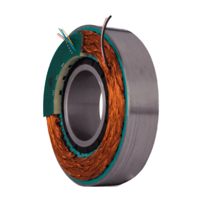
A robot motor is an electric motor used in robots and automated systems to facilitate motion.

As a component element employed to achieve mechanical movements, robot motors find applications in various parts of robots, such as joints and actuators. Their ability to control position and speed with high precision enables accurate operations and task execution. Stepping motors and servo motors, in particular, excel in this regard. Consequently, once programmed, these motors execute motions repeatedly, ensuring consistent results.

Moreover, they can achieve various types of movements, including rotational and linear, making robots adaptable to diverse tasks. An indispensable element in automated processes, robot motors enhance operational efficiency while reducing human effort.

However, precise control and programming of motors are crucial for realizing accurate movements. Proper motor drivers and controllers, along with suitable algorithms, need to be employed.

Uses of Robot Motor

Robot motors are widely used across various industries and applications. Here are some common examples of applications:

1. Industrial Robots

Industrial robots are utilized in automated production lines, contributing to activities such as assembling automobiles and manufacturing electronic devices. Due to the demand for high precision, servo motors and stepping motors are frequently employed in these robots.

2. Medical Field

In the medical field, surgical support robots enhance the precision of surgeries. These robots amplify the subtle movements of a surgeon’s hands, requiring high control accuracy. Additionally, rehabilitation robots assist in patients’ movement retraining and rehabilitation.

3. Service Robots

Service robots support various tasks in homes and commercial facilities. Cleaning robots perform tasks like floor sweeping and mopping, while drones assist in activities such as product delivery and photography. These robots possess advanced environmental awareness and motion control functions, ensuring efficient and safe operations.

4. Entertainment

The entertainment industry often employs theme park attractions and entertainment robots. These robots, equipped with flashy movements and lighting effects, provide people with enjoyment and surprises.

Principles of Robot Motor

Various types of motors are used as robot motors, with DC motors, stepping motors and servo motors being the most commonly used.

1. DC Motors

DC motors utilize the principle of electromagnetic induction. They can be categorized into brushed and brushless types. Brushed DC motors maintain rotation by using brushes and a commutator to change the direction of the current. Brushless DC motors, on the other hand, have an external control circuit that regulates the flow of current, offering high efficiency.

2. Stepping Motors

Stepping motors rotate in precise steps at specific angles. By supplying current to coils, a magnetic field is generated, causing the rotor to rotate and advance to the next step. Due to their ability to precisely control position, they are used in applications requiring accurate positioning and movements.

3. Servo Motors

Servo motors move at controlled speeds to specified positions. Using a feedback control system, the difference between the target and actual positions is detected, and the motor is adjusted accordingly. They excel in position control and are used for precise positioning in robot arms and machinery.

How to Choose Robot Motor

When selecting a robot motor, various factors need to be considered. Here are some factors to consider when choosing a robot motor:

1. Application

The type and performance of the motor to be chosen depend on its application. For instance, servo motors may be suitable when position accuracy is crucial, while brushless DC motors may be suitable for applications requiring high torque. Choosing a motor with characteristics and performance that match the application is essential.

2. Power Source Type

Robot motors can be powered by direct current (DC) or alternating current (AC). Choosing the appropriate power source type that aligns with the motor’s power requirements is crucial. DC motors are suitable for battery-driven applications, while AC motors are widely used when powered from outlets.

3. Capacity

The capacity of the motor is an indicator related to the torque and output the motor produces. Choosing a motor with the appropriate torque and output for the moving mass or load is essential. Using a motor with excessive or insufficient capacity may affect performance and lifespan.

4. Size

The size of the motor is an important factor to consider based on constraints such as available space for installation. In cases of limited space, a compact motor may be chosen, while applications requiring significant torque may involve selecting a larger motor.