カテゴリー
category_usa

Micro Pressure Gauges

What Is a Micro Pressure Gauge?

Micro pressure gauges are pressure gauges dedicated to measuring pressure as small as approximately 500 Pa or less.

Normal pressure gauges detect pressure according to the degree of deformation of a detector device called a “Bourdon tube.” The range of pressure measured by micro pressure gauges is so small that it cannot be measured with the same detector device.

One is the liquid column differential type, which is an improvement of the liquid column type pressure gauge and can measure minute movements of the liquid surface, and the other is the diaphragm type, which precisely measures the liquid surface difference based on the zero level method.

Uses of Micro Pressure Gauges

Micro pressure gauges are generally used to measure the pressure inside a tank. If heat is applied to the tank or gases other than air are used, the pressure will be different from atmospheric pressure and must be measured.

Therefore, examples of applications include gas pressure measurement and pressure measurement inside a combustion furnace. In addition to direct pressure measurement, micro pressure gauges may also be used to measure the volume and depth of liquid in tanks, etc., derived from the pressure.

Principle of Micro Pressure Gauges

There are two types of micro pressure gauges in general: the column differential type and the diaphragm type.

The liquid column differential type is an improved version of the liquid column pressure gauge, so the measuring principle is almost the same. The pressure is derived from the height of the liquid in the liquid column and the density and specific gravity of the contained liquid. Therefore, at sites where gas is handled, the height of the liquid column at atmospheric pressure changes, and the pressure is measured by detecting the change in the height of the liquid column.

The liquid column type requires compensation because the specific gravity of the liquid in the column changes with temperature, making it difficult to use for industrial applications. Diaphragm type pressure gauges use a Bourdon tube to detect pressure, but not directly, but through a thin membrane called a diaphragm, and an enclosed liquid contained in a vacuum to measure pressure.

Diaphragm type pressure gauges can measure the pressure of highly viscous liquids and liquids containing solids, which are usually said to easily clog pressure gauges.
カテゴリー
category_usa

Low Voltage Testers

What Is a Low Voltage Tester?

Low voltage testers are measuring instruments used to measure the voltage of lower voltage circuits.

By touching a low voltage tester to the part to be tested, it is possible to check whether electricity is present. The type of low-voltage detector used depends on the magnitude of the voltage of the circuit to be checked.

Usage of Low Voltage Testers

Low voltage testers are used where there is relatively low voltage flowing in the circuit.

Low voltage testers can measure voltages from 20V to 1000V, and can be used for products used in the home.

However, there are two types of electrical circuits, DC and AC, and it is necessary to use a different type of detector for each circuit.

Principle of Low Voltage Testers

All types of detectors, including low voltage testers, indicate whether or not electricity is present at the point where the detector makes contact. There are three types of signals: light, buzzer, and both. The detection methods can also be divided into two types: those that make contact with the sensing element and those that are non-contact.

However, the principle is the same for all of them. Normally, when electricity is flowing in a circuit, the electric field around it changes from when it is not flowing. Therefore, when a detector is brought into close proximity to the circuit, it detects this change in the electric field and notifies the user with light and sound.

How to Use Low Voltage Testers

A contact-type detector holds the detector firmly, and the side of the detector, not the tip, is in contact with the wire. If the wire is coated, the sensitivity of the detector is less than that of a bare wire, so it is necessary to make sufficient contact with the wire.

These are often used to confirm that there is no electricity and to perform subsequent work. However, care should be taken not to use them with wet hands, as there is a risk of electric shock in case of accident.

カテゴリー
category_usa

Metal Polish

What Is Metal Polish?

Metal polish is a liquid or paste containing an abrasive.

Metal polish can be used to remove oxide film, dirt, and other contaminants from metal by dropping it on the metal and then wiping it off with a cloth. Since all one has to do is simply drop it on the metal and wipe it up, it is relatively easy for anyone to use.

Metal polish contains various types of abrasives and their particles, so it is necessary to select the appropriate one depending on the type of metal and its finish.

Uses of Metal Polish

As the name suggests, metal polish is used to polish metal.

For example, stainless steel sinks start out polished, but as they are used, they lose their shine and water repellence due to water stains and fine scratches caused by rubbing against dishes. By removing these scratches and stains with Metal Polish, the surface can be made clean, and water repellence can be restored.


Principle of Metal Polish

Metal polish contains abrasive materials. When polishing metal and other materials, one often thinks of a whetstone, but what is contained in a Metal polish is more like a dispersed mixture of unconsolidated whetstone material.

Types of Metal Polish

The following three types are generally used:

1. Silicon Carbide

Silicon carbide, also known as carborundum, is the second hardest material after diamond, which is the hardest of the materials, and can be used for a wide range of hard metals such as knives and soft metals such as copper.

2. Black Silicon Carbide

Black silicon carbide is not as hard as green silicon carbide, it is more durable, making it suitable for polishing soft metals.

3. White Alundum

White alundum is a white high-purity alumina abrasive and the lowest hardness material of the three. It is suitable for polishing not only metals but also glass and crystal.

カテゴリー
category_usa

Current Clamps

What Is a Current Clamp?

Current clamps are devices that detect and measure the small amount of current that leaks from wires and other sources.

It is one of the clamp meters used to check whether current is flowing in the completed circuit itself, and the current value is checked by clamping the wire of the circuit to be checked. Although it was necessary to disconnect the circuit once to check the current, the clamp meter allows measurement without disconnecting the circuit.

Usage of Current Clamps

Current clamps are used in places where a current is flowing, and the device to be used depends on whether the circuit to be tested is a direct current or alternating current.

Because it can safely measure high-voltage currents as well as those in the home without disconnecting the circuit, it is also useful at the start of electrical work.

Principle of Current Clamps

Normally, when electricity is flowing through a wire, magnetic field lines are generated around the wire, even if the amount of current is slight. These magnetic field lines are picked up by the iron core, which is the core of the clamp meter, and the amount of current in the coil wound around the iron core is measured.

It is quite accurate because it can detect even the slightest amount of current, but clamp meters need to be used in different ways depending on the type of circuit.

Measuring different types of circuits will not give an accurate value and will make it impossible to determine the presence or absence of leakage current. So if the type is unknown, a DC clamp meter that can measure either circuit should be used.

カテゴリー
category_usa

Paper Bakelites

What Is Paper Bakelite?

Paper Bakelites are a type of Bakelite made by mixing phenol resin with paper as a base material.

In addition to Paper Bakelites, there are other types of Bakelites such as Cloth Bakelites that use cloth as a base material, and they are used in different ways depending on the situation. Paper Bakelites are strong, inexpensive, and have excellent electrical insulation properties. It is also easy to process, such as cutting and polishing, and can be used to make parts in a variety of shapes.

Uses of Paper Bakelites

Bakelite materials, including Paper Bakelites, are often used for electrical insulation because of their high strength and exceptional electrical insulation properties.

It is generally used inside equipment such as switchboards, but it is also used for electrical switches and knobs that control the volume of sound. Since these are places that people touch, Paper Bakelites are used for their high electrical insulation and easy shapeability to prevent electric shock.

Other Information on Paper Bakelites

1. Characteristics of Paper Bakelites

Paper Bakelites are a type of Bakelite. Bakelites are called laminates and are composed of phenolic resin and a base material. Paper Bakelites are distinguished by the term Paper Bakelites when the base material is paper and Cloth Bakelites when the base material is cloth.

Since these Bakelites are laminated plates, the surfaces perpendicular to the layers have considerably high mechanical strength, but the surfaces parallel to the layers are prone to delamination and have low strength.
When processing, it is necessary to check the direction in which force is likely to be applied while processing so that strength is maintained.

2. Manufacturing Method of Paper Bakelites

Paper Bakelites are manufactured by synthesizing phenol and formaldehyde to create phenolic resin. Since this alone lacks strength, paper, which serves as a reinforcing agent, is laminated in sequence and heated and pressed. Since paper is laminated between the layers, the paper part easily absorbs moisture and is not suitable for use in wet areas.

カテゴリー
category_usa

DC Voltage Tester

What Is a DC Voltage Tester?

A DC voltage tester is a type of detector that is used to measure the voltage of a DC circuit.

By placing the DC voltage tester in contact with the part to be tested, it is possible to determine whether electricity is flowing through the part.

Generally, AC voltage is used in most circuits where electricity flows, and voltage testers are generally used exclusively for AC voltage. However, there are some cases where DC circuits are used, such as in train lines and electrical cables. It is necessary to check if DC voltage testers are used in such circuits, as the use of an inappropriate one may result in electric shock.

Usage of DC Detectors

DC voltage testers are used in places where DC circuits are used and voltage is flowing. Common places include train lines and power plant cables.

When performing electrical work, we use an electric meter to confirm that there is no electricity before starting work. The places where electric inspectors are used are dangerous because electric current is flowing through them and touching them with bare hands may cause an electric shock. It is important to wear protective equipment when a high-voltage current is present.

Principle of DC Voltage Testers

DC voltage testers, like normal detectors, check to see if electricity is flowing at the point where the detector comes into contact with it.

Normally, when electricity is flowing through a wire, the electric field around the wire is variable. Therefore, when a detector is brought into proximity, it detects the changes in the electric field and emits a sound to indicate that electricity is present.

Types of DC Voltage Testers

The type of detector used depends on whether DC or AC circuits are being used. If it is necessary to check whether electricity is present on either circuit, use a DC detector that can measure both voltages.

The type of detector should also depend on the magnitude of the voltage. Note that a detector that can measure high-voltage current may not react if it is used in the low-voltage part of the circuit.

カテゴリー
category_usa

Thick Printed Copper

What Is Thick Printed Copper?

Thick printed copper is a type of copper substrate in which the thickness of the copper used is large.

Ordinary copper substrates have a thickness of 30-100 µm, while thick printed copper has a thickness of 140 µm or more. Thick printed copper can carry larger currents than normal copper substrates can, allowing for the operation of higher-power machines. Thick printed copper is being used more and more these days as high-power machines become more common.

Uses of Thick Printed Copper

Thick printed copper is necessary for high-power and high-current applications, and can dissipate the heat generated by high currents. Therefore, they are often used in small, high-current applications, and are often mounted in products that require greater durability. A particularly common application is power modules, which are electronic components for automobiles.

Originally, the power supply for automobiles and the distribution of power to electronic devices was done through dedicated power distribution, but this required complicated wiring, which was quite costly. However, the use of Thick printed copper has enabled high current flow, facilitating wiring design and making it possible to downsize products.

Principle of Thick Printed Copper

While most ordinary copper substrates have a thickness of 15 to 35 µm, thick printed copper has a thickness of over 140 µm. Because copper itself has high thermal conductivity, a larger current can be conducted in a smaller area by increasing the copper thickness.

Another feature is the high heat dissipation of the substrate itself. The higher heat dissipation of the substrate prevents the temperature of components from rising during operation, allowing them to operate more efficiently and extending the life of the components.

Types of Thick Printed Copper

There are four main types of thick printed copper:

  1. Busbar boards, which are made by embedding a metal busbar into the circuit.
  2. Cavity substrates with high heat dissipation, in which the conductors are exposed through a counterboring process.
  3. Copper inlay substrates with high heat dissipation, in which copper is injected directly under components that generate high heat.
  4. Thick printed copper with copper patterns of different thicknesses within a single substrate.

Thick printed copper with different thicknesses on the same surface allow multiple wiring designs on the same surface. It is important to select the right one for the intended use.

カテゴリー
category_usa

Tool Holder Bushings

What Is a Tool Holder Bushing?

Lathe Sleeves

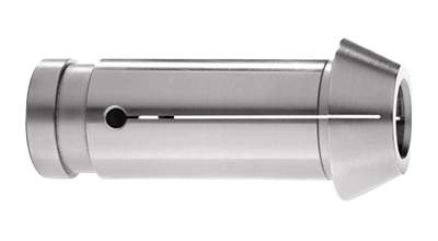
Tool holder bushings are tools used to attach the turning centers that hold the material and the bites that cut the material.

In mechanical engineering, a bushing is a cylindrical part designed to fit a machine. The outside diameter of tool holder bushings is designed to fit the holder, chuck, or collet attached to the turret or tailstock.

Tool holder bushings, on the other hand, are available in a variety of inner diameters to match the diameter of the bites to which they are attached.

Usage of Tool Holder Bushings

Tool holder bushings are mainly used for machining of materials such as metals, but other machining can also be performed by attaching a tool other than those used for machining through tool holder bushings.

Tool holder bushings are mainly used to attach boring bars, reamers, etc. when drilling with a lathe. Tool holder bushings equipped with a positioning mechanism can be used to fine-tune the center position for more accurate machining.

Principle of Tool Holder Bushings

Tool holder bushings are installed by inserting them into a holder or the like installed on the turret or tailstock. Then, a tool that matches the inside diameter of the tool holder bushing is inserted into the bushing and secured with a screw or other fastening part from the top of the holder.

Tool holder bushings with a positioning mechanism have a positioning screw in addition to the fixing screw hole, and the center position can be adjusted by turning this screw. The shaft of a boring bar or reamer that is inserted into tool holder bushings is called the shank, and its thickness is called the shank diameter.

When selecting tool holder bushings, it is important to make sure that the inside diameter of the bushing matches the shank diameter of the bites to be installed. Some tool holder bushings are equipped with a cooling mechanism to prevent the temperature of the turning tool from rising. Such products have holes drilled into the tool holder bushings through which coolant can be supplied.

カテゴリー
category_usa

Optical Multimeters

What Is an Optical Multimeter?

Optical multimeters are measuring instruments that use light.

They incorporate functions for measuring various optical characteristics. It is sometimes called an optical loss tester, optical loss tester, or optical loss test set.

The name “optical loss tester” is derived from the fact that it has an optical power meter to measure the intensity of light and a loss tester/return loss tester to measure how much of an optical fiber signal is lost. Some are also equipped with a laser as a light source and can be used as a stable light source.

Uses of Optical Multimeters

Optical multimeters are measuring instruments that use light in electrical circuits and are mainly used to measure current and voltage. Suitable for high-frequency current and high-voltage measurements, they are not only widely used in many industrial fields, but are also used in medical and other fields because of their high-speed and highly reliable measurements.

1. Testing Electronic Circuits

Optical multimeters can be used to measure voltages, currents, resistances, capacitance, etc. inside circuits to check the operating conditions of circuits. Optical multimeters are also suitable for checking the operation of high-speed circuits because of their high-speed measurement capability.

2. Temperature Measurement

Optical multimeters are also used for thermal imaging and non-contact temperature measurement, which detects infrared radiation emitted from surfaces to image temperature distribution. Examples include evaluating the thermal insulation performance of buildings and detecting overheating of electrical equipment.

Depending on the surface temperature of the object being measured, infrared or near-infrared radiation is emitted. By detecting this emitted light with an optical multimeter, the temperature of the object can be measured without direct contact.

3. Medical Treatment

It is used for the diagnosis and treatment of skin and eye diseases. In particular, ophthalmologists may use optical multimeters to diagnose and treat diseases such as glaucoma.

Another situation is the development of technology for functional brain imaging, which uses near-infrared light to non-invasively image brain activity. This is expected to find applications in the fields of neuroscience and clinical medicine.

Principle of Optical Multimeters

Optical multimeters are measuring instruments that utilize light in electrical circuits. The principles of signals and light sources are as follows.

1. Signal Principle

Optical multimeters transmit and receive light using optical fibers. The optical fiber is made of very thin glass fiber, which transmits light from the transmitter to the receiver.

The optical sensor at the receiving end receives the light and converts it into a signal, which is read as an electrical parameter of the circuit. In addition to enabling measurement with extremely high accuracy, this system is less susceptible to electrical noise in electrical circuits, enabling highly reliable measurements.

2. Principle of Light Source

Light-emitting diodes or laser diodes are the main light sources used for optical multimeters. These light sources are suitable for optical multimeters because of their low power consumption and very high brightness.

The transmitted light enters the circuit to be measured and is reflected, refracted, or scattered inside the circuit. These lights are again returned to the receiving section via an optical fiber, converted into optical signals by an optical sensor such as a photodiode, and displayed as measured values.

Thus, the use of optical fiber enables non-contact, highly-accurate measurements. Optical fiber is also suitable for high-speed measurements because it has less signal delay than electrical signals.

Characteristics of Optical Multimeters

Since measurement is non-contact, it is characterized by high safety and reliability and does not cause damage to the object being measured. On the other hand, since it measures the surface temperature of the measurement object, it cannot measure internal temperatures or the deterioration state of components.

Depending on the environment in which it is used, the accuracy of the measurement may be affected. Therefore, it is essential to understand the measurement target and conditions beforehand and to take measurements carefully.

カテゴリー
category_usa

Servo Drives

What Is a Servo Drive?

A servo drive is a device that controls a servo motor based on the values set by the controller in a servo system.

A servo system is a system of motor drives indispensable to industrial equipment for high-speed and precision control, and it is no exaggeration to say that servo drives make this possible. The main role of servo drives is to supply power to the servo motor, so it can do its job according to the load torque of the motor.

The servo drive can be divided into two parts: the part that performs power conversion and the part that detects the motor status and performs control operations.

Uses of Servo Drives

Servo drives are used in conjunction with motors in servo systems. They have a wide range of applications, from industrial equipment to machine tools.

The industrial robots used in automobile manufacturing plants, for example, are required to accurately repeat predetermined movements. To achieve this, it is necessary to accurately supply power commensurate with the load on the motor required for the operation to be performed. Servo drives monitor the condition of the motor while supplying the precise power needed to achieve this movement and torque to the determined position.

Other suitable applications where precision movement is required include semiconductor manufacturing equipment and medical equipment.

Principle of Servo Drives

The principle function of servo drives is amplification. They provide electrical feedback while closely monitoring the motor status — including rotation angle, speed, and current — with sensors, to facilitate precise motor control. A Programmable Logic Controller (PLC) or similar device is generally used as the controller for the amplification, setting the set values, and transmitting the information.

The servo drive supplies the necessary power to control the target set values, but for more accurate control, it is necessary to monitor whether the servo motor operation has reached the set values and to provide appropriate feedback. For this purpose, servo drives usually have a built-in sensor called an encoder.

The encoder comprises a disk with a slit and a built-in photodiode to detect the angular velocity and speed of the motor. Since the disk rotates in conjunction with the motor rotor, the speed and number of rotations can be monitored by detecting optical signals passing through the slits.

The photodiode detects these optical signals, converts them to an electrical current, and feeds it back to the amplifier. The amplifier generally uses the Pulse-width modulation (PWM) method to drive the motor by converting alternating current to direct current and then to an arbitrary frequency. This block consists of a converter section, a smoothing circuit section, and an inverter section. Encoder information is usually fed back to the inverter section.

Additional Information on Servo Drives

1. The Difference Between Inverters and Servos

In terms of motor control, inverters and servos are the same, but they have very different characteristics, and their applications can be broadly classified into two categories.

Inverters
Inverters have a wide range of applications, ranging from social infrastructure equipment such as air conditioners, elevators, and escalators, to industrial equipment and home appliances. Inverters are characterized by their ability to control the speed of motors and provide smooth and stable operation, especially when continuous operation with low power consumption is required.

Servo
Servos are valued for their high precision, facilitated by their ability to precisely adjust and control speed. Servos are preferable when high-speed, high-precision control of machine motion position is required.

2. Feedback Control of Servo Drives

Closed-loop control is normally used for servo drives based on sensor information from the encoder. However, in practice, due to workpiece shrinkage and misalignment between axes, deviation from the desired motion may occur even with feedback control. For this reason, there are servo drives that provide various phase compensation functions.

Additionally, depending on control timing, there are situations where fine adjustments to angular velocity are crucial.

For example:

  • Shortening the time it takes to reach the required rotational speed and phase angle during start-up and shut-down.
  • Ensuring a consistent rotational speed during normal operation.