カテゴリー
category_usa

Slide Core Unit

What Is a Slide Core Unit?
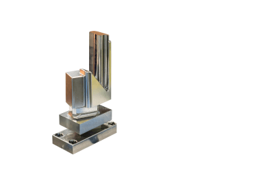
Slide Core Units

A slide core unit is a mold component primarily used in resin molding. It’s a movable part within a mold, facilitating the production of products with undercuts or complex inner geometries in a single molding process. Although integrating a slide core unit mechanism allows for intricate shapes in one go, it’s important to note the potential increase in tooling costs and design issues due to more detailed molds and additional parting lines.

Applications of Slide Core Units

Slide core units are essential for creating undercut areas in plastic molded products, which are shapes that obstruct the normal path of demolding. These units enable the forming of such areas, allowing for the product’s removal in one molding cycle. While a simple cup can be de-molded with a standard mold, a cup with a handle necessitates a slide core unit due to the undercut. This technology is also pivotal in producing complex plastic items like construction window frames, door handles, and electronic device housings.

To mitigate undercut challenges in complex parts, it’s often advisable to segment the part into manageable sections.

Principle of Slide Core Unit

The slide core unit employs a mechanism, often using pins or cam blocks, to de-mold products with undercuts by moving specific mold parts. This automatic opening and closing action, perpendicular to the mold’s opening, enables diverse shape creation. However, this complexity can lead to increased mold costs and reduced durability and maintenance ease compared to traditional molds. Design strategies often include reducing undercuts through part segmentation to manage costs effectively.

Types of Slide Core Units

There are various slide core units, distinguished by their movement mechanisms:

1. Slide Core Unit Method

Using an angular pin, this method involves a fixed angular contact and a movable slide core unit, noted for its simplicity and reliability.

2. Inclined Slide System

Featuring an inclined slide connected to a slide unit via a rod through the movable die’s inclined hole, this system activates upon ejection, moving the slide unit into the product.

3. Hydraulically Driven Slide System

This method uses a hydraulic cylinder, suitable for parts that are challenging to drive with angular pins, allowing independent slide movement or large unit handling.

Other Information on Slide Core Units

Utilization of Slide Core Units

Slide core units offer versatility in mold design, enabling the change of only the undercut shape within the same mold. This approach allows for varied product designs using a single mold. However, the complexity and number of molds can increase costs, maintenance challenges, and the occurrence of parting lines and burrs.

カテゴリー
category_usa

Space Heater

What Is a Space Heater?

A space heater is a type of heater that transfers heat to objects without direct contact.

Unlike conventional heating methods, space heaters don’t require physical contact with the object being heated, allowing for efficient and even heating. They are designed to transfer most of the heat energy directly to the object, minimizing energy loss. Additionally, because there’s no direct contact, the risk of fire or burns due to heat is reduced.

However, it’s worth noting that space heaters can be more expensive than traditional heating methods. Implementing the necessary equipment and technology can also be costly, and the applicability of space heaters depends on the underlying principle.

Uses of Space Heaters

Space heaters find applications across various fields. Here are a few examples of how non-contact heaters are used:

1. Industrial Applications

Space heaters play a vital role in industrial processes. They are used for tasks such as heating and melting metallic materials for casting and welding, as well as for forming and joining. In plastic molding, they facilitate the heating of plastic materials to aid in the molding process.

In glass processing, space heaters help control shaping and cooling to achieve desired shapes and properties. In semiconductor manufacturing, they are crucial for heating and heat-treating silicon wafers to produce precision components.

2. Food Processing

Space heaters are employed in food processing to remove moisture from foods through drying processes, extending shelf life and reducing weight. Heat sterilization is used to eliminate microorganisms from food products. In baking, space heaters ensure even heating for browning marks on food surfaces.

3. Medical Equipment

Medical equipment and instruments often use space heaters for heating purposes. They are essential for sterilizing surgical tools by applying high-temperature heat to kill microorganisms. In thermotherapy, space heaters are used to warm specific areas of the body, stimulating blood circulation and alleviating muscle tension.

Principles of Space Heaters

The primary principle behind space heaters is the transfer of energy through thermal radiation, with a common mechanism being the use of infrared radiation for heat transfer.

Infrared radiation is a form of electromagnetic radiation that is invisible to the human eye but carries thermal energy. Space heaters utilize electricity or gas as an energy source and emit infrared light to heat objects.

Infrared radiation boasts excellent heat transfer capabilities, allowing it to heat objects directly through the air. Moreover, infrared rays possess specific wavelength bands that are absorbed by objects, enabling efficient heating by selecting the appropriate wavelength band for the target object.

Types of Space Heaters

Various types of space heaters are available. Here are some examples:

1. Infrared Heaters

Infrared heaters operate by emitting infrared radiation to heat objects. Electric infrared heaters convert electrical energy into infrared radiation. They are utilized in a wide range of applications, including industrial heating and heating devices.

There are different types of infrared heaters, including ceramic heaters, which generate heat by passing electricity through ceramics. They are known for their quick start-up times.

2. Induction Heaters

Induction heaters employ an electromagnetic field to heat objects. A coil carrying an electric current generates an electromagnetic field that heats the object by inducing a current within the conductive material inside the object. These heaters are efficient for heating highly conductive objects and are used in cooking utensils and industrial heating equipment.

3. Microwave Heaters

Microwave heaters utilize microwaves to heat objects. Microwaves are generated by a device called a magnetron, and they heat objects by agitating water molecules’ movement. These heaters are commonly found in household microwave ovens and industrial heating devices.

4. Laser Heaters

Laser heaters use laser beams to heat objects. A high-energy light beam is directed onto an object, and the light energy absorbed by the object’s surface is converted into heat energy, warming the object. They are employed when precise heating control or localized heating is necessary.

カテゴリー
category_usa

Oilless plate

What Is an Oilless Plate?

Among the bearing plates used in machine tools, an oilless plate is one that operates without the need for lubrication.

These plates exhibit excellent wear resistance in areas where it is relatively difficult to maintain an oil film due to reciprocating motion, machine vibrations, and frequent start-ups and shutdowns.

Oilless plates come in various types. Some have solid lubricant embedded in round hollows, while others incorporate solid lubricants into the plate material itself. Additionally, there are types that employ materials with low coefficients of friction for the bearing plates, rendering them completely oilless.

Applications of Oilless Plates

Oilless plates are frequently employed in bearing applications where lubrication is mechanically challenging or where the use of oil is prohibited for hygiene reasons, such as in food and beverage machinery.

Oilless plates can also be used in conjunction with lubricating oil to further reduce the coefficient of friction and enhance the performance of machine tools.

Moreover, compared to traditional plates, the use of lubrication, including the cost of oil and various machine design expenses for lubricated components, can be minimized, making oilless plates an attractive option for this purpose.

Principles of Oilless Plates

The principle of oilless plates depends on the plate material and can be broadly categorized into three methods.

The most common method involves using a plate with solid lubricant, such as graphite, embedded in round indentations. This type of plate operates without the need for additional lubrication equipment for the machine, as long as the manufacturer’s recommended lubricant is used.

Another method blends the metal material of the plate with substances exhibiting low coefficients of friction, such as molybdenum disulfide, or involves the blending of lubricants. Combining these materials allows for the creation of a bearing plate with a low coefficient of friction, eliminating the need for lubrication. This category also includes plates with a thin lubricant layer on the surface or plates coated with resin-based materials with low coefficients of friction.

Finally, engineering plastics with low coefficients of friction can be used as alternatives to metal for oilless plates. Materials like polytetrafluoroethylene (PTFE) and polyacetal resin fall into this category.

In rare cases, specialized manufacturers may be contracted to provide processing services to meet the demand for oilless plates for standard bearing applications.

カテゴリー
category_usa

Ball Guide

What Is a Ball Guide?

A ball guide is a guiding component that utilizes the rolling capability of a ball to enable linear motion with minimal friction. Ball guides are primarily installed on shafts to facilitate low-friction linear motion along the shaft’s longitudinal axis. In addition to ball guides, there are roller guides that share similarities with ball guides.

A typical low-friction ball bearing is an example of a ball bearing. While this type of bearing primarily supports rotational motion rather than linear motion, it employs the same principle of achieving low friction through the rotation of balls.

Applications of Ball Guides

Ball guides are predominantly utilized as integral components of linear motion mechanisms in machinery. Due to their function in reducing friction, they are seldom employed in isolation but rather in conjunction with a stage or bracket where a shaft is utilized to compensate for vibrations or to support the conveyance of objects.

Various types of ball guides exist, including ball bushings and linear bushings with a cylindrical shape designed to fit onto a shaft, as well as linear guides with a flattened structure that can also serve as a stage.

Principles of Ball Guides

Ball guides comprise a guidepost, a ball retainer, and a bush. The ball guides operate by applying pressure to facilitate the rolling of balls between the bush and the guidepost. While they offer cost-effectiveness, their load capacity is slightly lower compared to roller guides.

Linear guides have a structure where balls make contact with the rail surface, and they include ball rolling grooves. Consequently, they offer a higher allowable load capacity, meaning they can move the ball while bearing a load. However, this complexity and enhanced performance come at a higher cost.

Linear bushings, on the other hand, are compact and lack rolling grooves. As a result, the contact area of the ball is smaller, and their allowable load capacity is lower. Essentially, they are used for guiding rather than bearing loads. For instance, they can be employed as guides for linear motion along the longitudinal axis of a shaft fixed to a bearing.

カテゴリー
category_usa

Linear Stopper

What Is a Linear Stopper?

A linear stopper is a metal fitting designed to prevent a work plate, which serves as a mounting base for a workpiece, from dislodging from a guide rail, such as a linear guide or slide rail, or for precisely positioning the work plate. It is also commonly referred to as a linear stopper or linear lock.

Linear stoppers are typically constructed from steel or stainless steel. Some stoppers come equipped with urethane rubber or urethane rubber bolts to minimize impact between the table and the stopper. The bolts and other components of the stopper are crafted from S45C steel, which undergoes hardening to enhance wear resistance.

Applications of Linear Stoppers

Linear guides find usage in situations demanding precise linear motion, and linear stoppers are installed at their ends. They are employed in machine tool tables, transportation equipment, processing and inspection tables for semiconductors, among other applications, to prevent tables from dislodging and to facilitate precise positioning.

In recent years, linear stoppers have found utility in linear guides for railroad cars, buses, automatic doors, and seismic isolation devices.

Linear stoppers fitted with sensors are also widely adopted for the automatic control of industrial machinery.

Characteristics of Linear Stoppers

Linear stoppers come in three main types: those for retention, those for precise positioning, and those designed to work in conjunction with urethane rubber or urethane bolts. The stopper block is employed to prevent the work plate from dislodging from the guide rail or to act as a stopper if the work plate goes out of control. They can also be used for simple positioning in conjunction with stopper blocks.

Precision positioning involves the use of stopper bolts and stopper blocks, with stoppers specifically designed for this purpose. For even greater positioning accuracy, linear stoppers with bolts may be used in combination with stopper blocks featuring bolts.

Urethane rubber with urethane bolts serves to minimize noise resulting from metal-to-metal collisions between the work plate and the stopper block. The urethane bolt features a urethane rubber attachment at the bolt head, and the rubber part can be replaced when necessary.

Additionally, there are compact linear stoppers available, designed for installation in confined spaces, featuring a downsized design for enhanced versatility.

カテゴリー
category_usa

Try Plate

What Is a Try Plate?

A try plate is a type of jig used in machining. It is an L-shaped or cube-shaped jig used to attach the product to be machined at right angles to the base surface.

Each face is made of a quality flat surface with no unevenness, and the L-shaped part or cube has a precise 90-degree angle.

A try plate has tapped holes, through holes, and long holes for attaching jig components such as clamps and workpiece guides, allowing for a wide variety of processing on various products.

Uses of Try Plates

Try plates are used for the following applications:

  1. Beveling the Workpiece on the Surface Plate
    When drilling or tapping a workpiece with a drill plate, try plates are used to mark the hole positions in advance.
    The workpiece to be machined is set at the exact 90-degree angle made by the surface plate and try plates, and a line is drafted with a needle or the like, taking the dimensions from the edge of the workpiece.
  2. Use for Horizontal Machining Sensor Jigs
    Because the spindle of a horizontal machining center is horizontal, the product to be machined must be mounted parallel to the spindle. Therefore, the try plate jig is used to clamp the workpiece for drilling, milling, etc.

Principles of Try Plates

Try plates are used as a jig for machining products on a horizontal machining center.

Since the quality of the workpiece clamped on the try plates is greatly affected by the accuracy of the try plates, the structure of the try plates has important principles and principles.

The spindle of a horizontal machining center faces parallel to the floor and is perpendicular to the workpiece fixed to the try plates jig facing it.

If the relationship between the spindle and the workpiece deviates from 90 degrees, the flat surface of the workpiece will be machined at an angle when milling, for example.

As a countermeasure, the try plates itself can be milled on a horizontal machining center.

In this way, the workpiece mounting surface of the try plates are finished to the same accuracy as the spindle.

However, in a production line using a pallet changer, one try plates jig may be mounted on several horizontal machining centers.

Since each of these horizontal machining centers has a slightly different spindle orientation, it is not possible to finish the try plates surface to fit all of them.

In such cases, the jig’s swivel function of the horizontal machining center is used to tilt the origin intentionally and process the work perpendicularly.

カテゴリー
category_usa

ID Clamp

What Is an ID Clamp?

An ID clamp is a cutting jig. After centering a workpiece with a hole for location, the clamping jig secures the workpiece from the inside by the wall of the hole. The mouth part of the clamp is divided into several parts, which are spread by the clamping operation to fix the ID clamp on the inside diameter of the workpiece. By clamping the workpiece only from the inside, interference between the clamping jig and the machining tool is avoided, making it suitable for clamping workpieces with many machining points, multiple-piece machining, and thin-walled parts.

The clamp drive system can be manual, pneumatic, or hydraulic, and the easy-to-use manual ID clamp is widely used.

Since the workpiece location hole is used for clamping, highly accurate positioning is possible.

Uses of ID Clamps

Since cast parts have large tolerances on the periphery, ID clamps that use a hole for locating are often used. ID clamps are also used when there is no clamping point on the periphery of the workpiece, when the clamping fixture interferes during machining, when the workpiece is thin-walled, or when a special jig is used to clamp numerous pieces.

Some ID clamps can also be clamped from the outside of the workpiece by replacing the (clamping) clamp. This makes it easy to clamp even complex-shaped workpieces and is convenient for use in multi-cavity and dive machining.

Features of ID Clamps

When machining the top or side surface of a workpiece, the machining tool may interfere with the clamping jig when clamping in the vertical or horizontal direction. In this case, the use of ID clamps, which do not clamp the outer surface of the workpiece, eliminates the interference and allows the outside of the workpiece to be machined freely.

When many workpieces need to be clamped at once to increase productivity, the clamping jig takes up a lot of space, limiting the number of clamps that can be installed. With the compact ID clamps, a large number of workpieces can be clamped, allowing continuous machining in a single setup.

For thin-walled workpieces, the use of a standard 3-jaw chuck may cause clamping distortion due to uneven clamping force. In this case, the use of an ID clamps is suitable. ID clamps have a finely divided clamping jaw that presses evenly on the ID of the workpiece, thus minimizing workpiece distortion.

ID clamps have the advantage that the workpiece can be positioned precisely at the same time if clamped. The holes used for clamping are highly accurate, and by tightening the screw, the mortise part of the mouthpiece opens and clamps from the inside, allowing repeated positioning with high accuracy.

カテゴリー
category_usa

Charge late Analyzer

What Is a Charge Late Analyzer?

A charge late analyzer is an instrument that evaluates the static elimination performance of an ionizer. The performance evaluation of ionizers for the purpose of controlling static electricity and static elimination is specified in the international IEC standard. Charge late analyzer is used to evaluate and monitor static elimination time and ion balance.

The charge late analyzer is supplied with a metal plate of a predetermined size, which is charged, and then the ionizer is activated to measure the decay time of the static charge. The ion balance is evaluated by measuring the electrostatic potential of the electrodes after a certain period with the metal plate uncharged.

Uses of Charge Late Analyzers

The charge late analyzers are mainly used to measure and control the static elimination performance of ionizers. It has the advantage of visually displaying the field strength, charge potential, and decay time of static electricity, which are not visible to the naked eye.

Examples of applications include the detection of discharge in semiconductor and LCD manufacturing equipment, identification of the location of discharge in the manufacturing and mounting processes of electronic components, and evaluation of static elimination products. It is also used to determine malfunctions caused by electrostatic discharges in electronic equipment and to verify anti-electrostatic measures in manufacturing processes. Other applications include measuring the charge decay of tools and determining the antistatic effectiveness of semiconductor storage cases and bags.

Principles of Charge Late Analyzers

An ionizer removes static electricity by generating ions that strike an object. In evaluating the performance of the ionizer, it is important to measure the ion balance, which is the mixing ratio of positive and negative ions. Charge late analyzers, an electrically insulated and uncharged metal plate, is placed in the ions coming out of the ionizer, and the electrostatic potential of the electrode is measured to determine whether the polarity and electrostatic potential are positive or negative and how much they deviate from each other. An ion balance of 0 V is the ideal ionization performance of the ionizer. It is specified that a metal plate 150 mm square per side with a capacitance of 20 pF should be used.

To evaluate the ionizer’s speed of static elimination, the decay time, or the time it takes the ionizer to neutralize the electrostatic charge stored in a charged electrode with a capacitance of 20 pF, is measured with charge late analyzers. Decay time is measured by measuring the time it takes for the potential of the charged metal plate to decay to 10%. A short decay time has a strong static elimination capability, but care must be taken with semiconductors, as they may be destroyed if they are eliminated in a short period by highly concentrated ions.

カテゴリー
category_usa

eSIM

What Is an eSIM?

eSIMs

eSIM (Embedded SIM) is a digital version of a physical SIM card, pre-embedded in devices like smartphones, tablets, and smartwatches. It can be programmed remotely, allowing users to switch between different telecommunication services without needing a physical SIM card. eSIMs are particularly useful for roaming and in devices requiring multiple communication providers, including IoT devices.

Uses for eSIMs

eSIMs are versatile and find applications in various devices and scenarios due to their flexible and remotely controllable nature.

1. Smartphones and Tablets

eSIMs are increasingly adopted in smartphones and tablets, enabling users to switch carriers easily and facilitating international roaming without needing new SIM cards.

2. Wearable Devices

Wearable devices like smartwatches benefit from eSIMs, offering independent communication capabilities and enhancing user convenience.

3. Notebook PCs

Mobile notebook PCs are integrating eSIMs to eliminate the need for microSIM slots, contributing to a more compact and lightweight design.

4. In-Vehicle Systems

eSIMs are used in in-vehicle systems for real-time navigation and entertainment services, as well as for remote vehicle management and emergency communication.

5. IoT Devices

In IoT devices, eSIMs facilitate efficient management and allow the flexibility to switch communication providers as needed.

Principle of eSIMs

An eSIM functions similarly to a nano-SIM but is directly mounted on the motherboard of a device. Each eSIM has a unique ID used for authentication and contract management. Network operators can remotely control the eSIM’s profile via OTA (Over the air), enabling users to easily switch carriers.

Types of eSIMs

eSIMs are categorized into M2M and consumer models.

1. M2M Model

The M2M model is designed for embedding in IoT devices, optimized for communication with specific servers, and simplified for limited functionality.

2. Consumer Model

The consumer model is intended for devices operated by end-users, providing full operational control from the user’s terminal.

Other Information on eSIM

1. The Difference Between a SIM and an eSIM

eSIMs differ from traditional SIM cards in form, usage, and user benefits. Unlike physical SIM cards, eSIMs are integrated into devices, allowing users to switch communication providers remotely without needing to replace the SIM card.

2. Advantages and Disadvantages of eSIM

Advantages:

  • Flexibility: eSIMs simplify provider changes, eliminating the need for physical SIM cards.
  • Device Miniaturization: The absence of physical SIM cards allows for smaller device designs.
  • Integration With IoT: eSIMs enable efficient management of numerous IoT devices.

Disadvantages:

  • Limitation of Providers: Not all telecommunication providers currently support eSIM, requiring users to find compatible providers.
  • Technical Issues: Without a physical card, transferring information to a new device can be challenging in case of device problems.
カテゴリー
category_usa

PROM

What Is a PROM?

PROMs

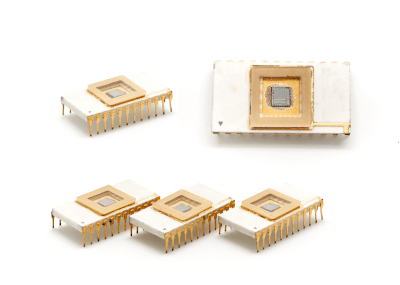
A PROM (Programmable Read Only Memory) is a type of semiconductor memory that is writable.

There are two main types of semiconductor memory: RAM (Random Access Memory), which can read and write, and ROM (Read Only Memory), which can only read.

RAM is a volatile memory that loses data when the power is turned off, while ROM is a nonvolatile memory that retains data even if the power is turned off.

There are two types of ROM: mask ROM and PROM. In mask ROM, the output value of the transistor for each bit of memory is fixed to either the supply voltage or ground during the semiconductor manufacturing process, so it cannot be changed after manufacturing.

In contrast, PROMs are nonvolatile ROMs developed to allow writing and rewriting after manufacturing.

Uses of PROMs

Microcontrollers used to control various devices have specific programs for each device and must operate upon power-on, so programs are stored in nonvolatile, low-cost ROMs.

Initially, mask ROMs were used as the primary type of ROM. However, the time from program finalization to manufacturing completion is long, making it difficult to respond to the shortened development cycles of new products.

Additionally, the need to produce a wide variety of products in small quantities due to the diversification of consumer needs has required the separate manufacturing of semiconductor chips.

In contrast, PROMs can be written even after the program has been debugged and finalized. This allows for the shortening of the development period by writing the program immediately before product shipment and for the development of new products by changing only the program.

Principles of PROMs

PROMs can be broadly classified into OTPROM (one-time PROM) and EPROM (erasable PROM). OTPROM is a type of PROM that can be written only once, while EPROM is a PROM that can be written multiple times.

1. OTPROM

OTPROM has a fuse for each bit of memory, and after shipment, some fuses are blown by selectively applying a high voltage. The transistor connected to the blown fuse, and the transistor connected to the unblown fuse have different current supplies, which distinguish between a0 and a1. A special tool is required for writing.

Once a fuse is blown, it cannot be restored, so it can only be written once.

2. EPROM

In EPROM, an electrically isolated region called a floating gate is formed in the manufacturing process in the transistor for each bit of memory. When writing, a voltage is selectively applied to the floating gate to store an electric charge, creating the difference between a0 and a1.

For rewriting, the memory charge in the target area is erased and then written again. There are UV-EPROM and EEPROM, depending on the erasure method.

UV-EPROM
UV-EPROM erases the charge by exposing the memory area to UV light (ultraviolet light). For this purpose, UV-EPROM has a window for UV light irradiation on the semiconductor package.

EEPROM
EEPROM allows data to be erased and rewritten by applying a higher voltage to the memory area than during normal read operations.

Other Information About PROMs

1. Expansion of Applications

The original use of PROMs was limited due to their high manufacturing cost. However, the use of PROMs has been expanding as their cost has decreased due to technological development and mass production.

In particular, flash memory (flash ROM), a type of EEPROM, has realized large capacity and high speed by simplifying the circuit to erase a large area of memory at once. The upper limit of rewritable cycles has been increased to several tens of millions, expanding applications that take advantage of its nonvolatility, and it is now used as a storage device in SD, USB, SSD, HDD, etc., becoming the mainstay of current memory technology.

2. Future Prospects

In the future, it is expected that non-volatile, low-cost memory with an unlimited number of rewrites will be put to practical use. Once this is realized, for example, PCs will no longer need to be started up and shut down, and can be used by simply turning the power on and off, as with lighting fixtures.