カテゴリー
category_usa

Sequence Valve

What Is a Sequence Valve?

A sequence valve is a type of pressure control valve that ensures actuators, such as hydraulic cylinders, operate in a specific sequence within hydraulic circuits. This is crucial for systems requiring a predetermined order of operations, allowing for one actuator to complete its task before the next begins.

Uses of Sequence Valves

Sequence valves are integral to various industries and machinery, including food and semiconductor manufacturing, as well as construction equipment like cranes and forklifts. These valves enable the precise control of power in hydraulic systems, facilitating the movement of machine tools and large machinery.

1. Manufacturing Industry

In press machines, sequence valves control the sequential operations from material input to product discharge, ensuring large forces are applied in a controlled manner.

2. Construction Machinery

Used in mobile cranes, sequence valves manage the order in which the crane’s jibs extend and retract, ensuring smooth operation.

Principle of Sequence Valves

A sequence valve directs flow from the primary side to the secondary side once the primary pressure exceeds a set threshold. This action is controlled by a spool within the valve that moves in response to pressure changes, allowing sequential actuator operation.

Structure of Sequence Valves

Comprising a body, spool, ports, a pressure adjustment screw, a spring, and a check valve, sequence valves feature input, output, and drain ports. The operation timing can be finely adjusted via a spring under the adjusting screw.

Types of Sequence Valves

Based on the source of pilot pressure, sequence valves are categorized into:

  • Internally Piloted Type: Utilizes internal pilot pressure.
  • Externally Piloted Type: Uses external pilot pressure.

How to Select a Sequence Valve

Selection criteria include the pressure and flow rate of the circuit, which influence the timing and force of operations. Proper selection is crucial to prevent damage and ensure efficient operation. Understanding the override characteristic, where output gradually shifts to the secondary side before reaching the set pressure, is also important.

Other Information on Sequence Valves

Sequence Valve Operating Order

The typical operating sequence in a hydraulic circuit involves:

  1. Oil flows to the first cylinder, activating it while the second cylinder remains closed.
  2. Upon the first cylinder’s completion, circuit pressure rises, causing the spool in the sequence valve to move and release output to the second actuator.
  3. The second cylinder then begins to move, followed by the activation of the second actuator.

This process ensures that each actuator operates in turn, based on the preset pressure thresholds.
カテゴリー
category_usa

Schmidt Coupling

What Is a Schmidt Coupling?

Schmidt Couplings

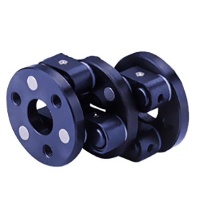
A Schmidt coupling is designed to connect two parallel shafts with varying shaft center distances in rotating equipment, enabling efficient power transmission even when the shafts are not aligned.

Uses of Schmidt Couplings

Schmidt couplings are versatile, allowing for the connection of shafts that are offset by a few millimeters to several tens of millimeters. Some models can adjust the distance between shaft centers while in motion, making them ideal for a range of applications:

1. Parallel Shaft Connection

For connecting parallel shafts with different center distances, Schmidt couplings provide a simpler and more compact solution compared to universal joints, gears, belts, and pulleys, which can be cumbersome for small offsets.

2. Roll-Forming Machine

In roll-forming machines, where rolls need to move vertically for spacing adjustments, Schmidt couplings allow for continuous operation without affecting the rotation, even when the motor position is fixed. This functionality is also beneficial in textile machinery for adjusting feed rolls.

Principle of Schmidt Couplings

Schmidt couplings utilize an off-axis, link motion mechanism. This system involves a series of links evenly spaced around a center disk, maintaining constant phase alignment between the end disks and the center disk. The unique design allows the center disk to rotate in sync with the end disks, regardless of the distance between shaft centers, while maintaining a constant link length.

Structure of Schmidt Couplings

The coupling consists of two flanged end disks and a central disk, connected by multiple links. These links are fitted with needle bearings to ensure smooth operation, with thrust washers and stoppers preventing disconnection. An oil seal and cap keep out contaminants, maintaining the integrity of the coupling.

Other Information on Schmidt Couplings

1. Material of Schmidt Couplings

Mainly constructed from carbon and stainless steel, with hardened steel or bearing steel for the moving parts like pins, Schmidt couplings are built for durability and longevity.

2. Precautions for Use

These couplings are not suited for shaft connections with significant angular misalignments. The design allows for minimal clearance and misalignment, requiring careful consideration to avoid axial or bending forces that could damage the coupling.

3. Limitation of Use Near Concentricity

While effective for parallel shaft adjustments, Schmidt couplings are not recommended for nearly concentric positions due to instability in the linkage motion. Care must also be taken to avoid interference with surrounding components during operation.

カテゴリー
category_usa

ThermoCon

What Is ThermoCon?

ThermoCon is a distinctive type of concrete known for its high expansion rate, fluidity, and hardening characteristics. After being poured, ThermoCon bubbles and expands significantly, enabling it to spread thoroughly and fill every corner without leaving gaps.

Before expansion, ThermoCon is highly fluid, allowing it to penetrate narrow entrances and fine gaps easily. This feature makes it particularly useful in various construction and repair situations.

Uses of ThermoCon

ThermoCon is primarily used for filling cavities and gaps, especially in scenarios such as subsidence repair and underground construction. For example, it is utilized to fill voids created by subsidence or flooding, preventing ground surface cave-ins or accidents. ThermoCon is also employed in tunneling and water pipe installation, where it fills the gaps and cavities to enhance safety and durability.

Principle of ThermoCon

ThermoCon’s effectiveness as a filling material is due to several key properties:

  • Highly Expandable: ThermoCon expands approximately 1.4 to 2 times its original size during the foaming and hardening process, ensuring thorough coverage. This feature also means that only a small amount is needed, reducing transportation challenges and manufacturing costs.
  • High Fluidity: Before solidification, ThermoCon has low viscosity and flows smoothly. This fluidity facilitates easy transportation, quick penetration into tight spaces, and reduces filling time.
  • Excellent Versatility: ThermoCon can be manufactured with varying properties by altering its formulation, allowing customization for different applications, such as adjusting air content or compressive strength.
カテゴリー
category_usa

Auto Tensioner

What Is an Auto Tensioner?

Auto Tensioners

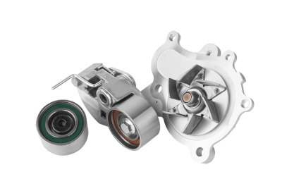
An auto tensioner is a device designed to maintain the correct tension of a chain or belt in power transmission applications. It automates the task of keeping the tension appropriate, hence the name “automatic tensioner.” Auto tensioners are crucial in various settings, including in automobile engines and air conditioning systems, playing a significant role in enhancing engine efficiency and reliability.

Auto tensioners automatically adjust to changes in belt tension, which may occur due to stretching or loosening. This automation removes the need for periodic manual adjustments and inspections, thus simplifying maintenance and lowering associated costs. Ensuring proper tension is critical for the efficient operation of the engine and other mechanically driven components.

Uses of Auto Tensioners

Auto tensioners are versatile mechanical devices found in belt drive systems across multiple applications:

1. Automobiles

In automotive engines, belts drive accessories like generators and air conditioning compressors. Auto tensioners ensure these belts maintain the correct tension, critical for the accessories’ optimal operation in sync with engine rotation.

2. Generators

Generators, powered by engines or other mechanisms to generate electricity, rely on belts for power transmission. Auto tensioners keep the generator belt under constant tension, ensuring efficient operation and a stable electricity supply by preventing belt loosening or stretching during extended use.

3. Agricultural Machinery

Belt drives in tractors and combine harvesters, driving components like the mowing unit and grain processing machinery, benefit from auto tensioners. These devices maintain steady drive belt tension, enhancing the stability and efficiency of agricultural operations.

4. Air Conditioners

Auto tensioners are used in air conditioners, particularly on the drive belts of compressors, to maximize cooling capacity and regulate indoor temperatures effectively.

Principle of Auto Tensioners

Auto tensioners utilize a spring mechanism to maintain the belt at the proper tension. This mechanism, often a compression or torsion spring, adjusts the tension on the belt as needed. When the belt loosens or stretches, the spring mechanism adjusts the force on the pulleys to either increase or decrease tension accordingly, ensuring the belt maintains the designed tension value.

Types of Auto Tensioners

Auto tensioners are categorized into mechanical and hydraulic types, each suited to different applications.

1. Mechanical Type

Mechanical auto tensioners use a spring action to manage chain or belt tension. These typically feature two coil springs within the unit, with an idler sprocket or sliding shoe adjusting the chain’s slack and tension.

2. Hydraulic Type

Hydraulic auto tensioners adjust tension through hydraulic pressure, ideal for situations where mechanical types are insufficient, such as in high-load applications causing angular vibration. This type consists of a tensioner pulley and a hydraulic actuator, with the actuator’s piston rod movement adjusting the tension through a lever and link mechanism. They are commonly used in automotive engine belts.

カテゴリー
category_usa

End Plate

What Is an End Plate?

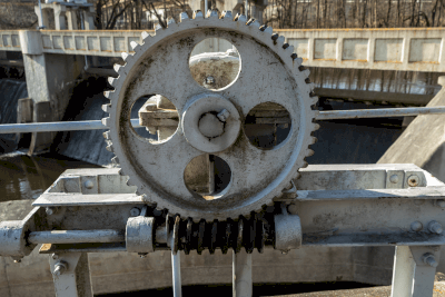
End Plates An end plate is a versatile component used in various devices across different industries. Generally, it refers to a plate-like part that is attached to the end of a piece of equipment or device. The term ‘End Plate’ is often interchangeable with terms like end cover or edge plate due to its broad applicability and convenience.
Uses of End Plates

End plates serve multiple purposes, depending on the specific equipment they are part of. Common uses include:

  • Serving as covers for the end sections of motors, terminal units, and similar devices.
  • Securing shafts in mechanical systems such as in reduction gears. Here, an end plate may feature screw holes for bolting it securely to the shaft.

Principle of End Plates

End plates play a critical role in mechanical assemblies. For instance, when mounting a gear reducer to a motor for torque enhancement, the rotating shaft attached to the gear head may be secured between two end plates using bolts. The requirement for end plates can vary depending on the type of gear reducer.

In other cases, such as terminal units, end plates might be used for aesthetic reasons or to ensure safety by covering open ends. Additionally, in automotive applications, end plates are often found on sports cars with wings. These fin-shaped plates are attached to the ends of wings and aligned vertically, providing stability to the vehicle at high speeds by managing air pressure effectively.

カテゴリー
category_usa

ABLE Reducer

What Is an ABLE Reducer?

An ABLE reducer is a product name for servo motor reducers, including two main product lines: the ABLE series with concentric shafts and the ABLE series with orthogonal and hollow shafts.

ABLE reducers are known for their quiet operation, lightweight, and compact design. They are among the most well-known products in their category, largely due to the extremely short lead time from order to delivery.

Uses of ABLE Reducers

ABLE reducers are designed for use with servo motors and are therefore found in devices that utilize servo motors. These include printing presses, foundry robots, packaging machines (both vertical and horizontal pillow types), dispenser robots, turret heads, conveyor belts, automatic boxers, and loader robots.

Servo motors, essential for industrial robots, allow for precise control over rotational position and speed. They are critical in factory automation equipment, including semiconductor and LCD manufacturing devices, where precise positioning is necessary, often requiring the use of reduction gears.

Principle of ABLE Reducers

ABLE reducers combine a servo motor with a reducer for several reasons, such as achieving the required torque and controlling rotation speeds. Without a reducer, a larger servo motor and controller would be necessary for these tasks. However, using a speed reducer allows a smaller servo motor to generate greater torque and maintain appropriate rotation speeds without a control device.

Servo motors, therefore, often require a reduction gear. The coaxial ABLE Reducer uses planetary gear reducers, while the orthogonal shaft and hollow shaft types utilize hypoid gears, bevel gears, and worm gears.

Structure of ABLE Reducers

ABLE reducers, compatible with servo motors from multiple manufacturers, use planetary gear trains in the concentric shaft type, aligning the servomotor and output shaft. By combining one or two sets of planetary gear trains, the desired reduction ratio is achieved on the same shaft.

A planetary gear train includes a sun gear at the center, a planetary carrier surrounding the sun gear, and a ring or internal gear encircling these components. The planetary carrier holds three or more pinions that rotate and orbit between the sun gear and the ring gear, resembling the movement of planets, hence the name.

In a planetary gear train, fixing one element and rotating another causes the third element to rotate differently, enabling deceleration, acceleration, and direction reversal. By combining multiple planetary gear trains, a wide range of reduction and acceleration ratios can be achieved, making it suitable for high torque applications and widely used in automatic transmissions for automobiles. ABLE reducers leverage this mechanism to offer large reduction ratios in a compact form factor.

Types of ABLE Reducers

ABLE reducers are categorized into concentric shaft, orthogonal shaft, and hollow shaft types, each available in multiple series based on the application. Each category offers various sizes, allowable torques, and reduction ratios.

カテゴリー
category_usa

Worm Wheel

What Is a Worm Wheel?

Worm Wheels

A worm wheel is a gear that makes up a worm gear.

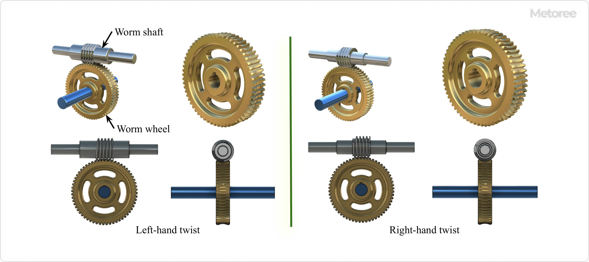
A worm gear is a type of screw gear. It is a combination of a worm (worm shaft), which is a threaded toothed shaft, and a Worm Wheel, which is a helical gear with its axis of rotation at 90 degrees to the worm’s axis.

Rotation of the worm feeds and rotates the teeth of the worm wheel that engage the worm.

Figure 1. Structure of worm gear

Figure 1. Structure of worm gear

Uses of Worm Wheels

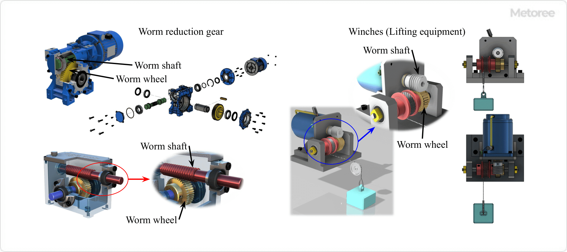
Figure 2. Example of worm gear (worm wheel) use

Figure 2. Example of worm gear (worm wheel) use

Worm wheels are used in combination with worms (worm shafts) as worm gears.

Worm gears are orthogonal shafts that can transmit power by changing the direction of the input and output rotary axes by 90 degrees, and can produce large reduction ratios, even with small gears. This includes devices, such as belt conveyors in factory equipment, screw jacks, steering systems for automobile steering wheels, wiper drives, and swiveling mechanisms for electric fans. It also includes material feeders in food and drug manufacturing equipment, music boxes, and stringed instrument pegs.

1. Machine Tools

Worm wheels are used in machine tools such as lathes and milling machines.

2. Conveyor

High torque for moving heavy loads and smooth belt movement.

3. Elevators

Used in hoisting devices for elevator carriages. It can provide the power needed to lift and lower heavy loads and smooth operation.

4. Automotive Steering Systems

Worm wheels are used in power steering systems in cars, trucks and other vehicles. Worm gears are used in some reduction gears for power steering drives. 

5. Winches (Lifting Devices)

Worm gears are used in some winches. They output high torque and can lift heavy loads.

Principle of Worm Wheels

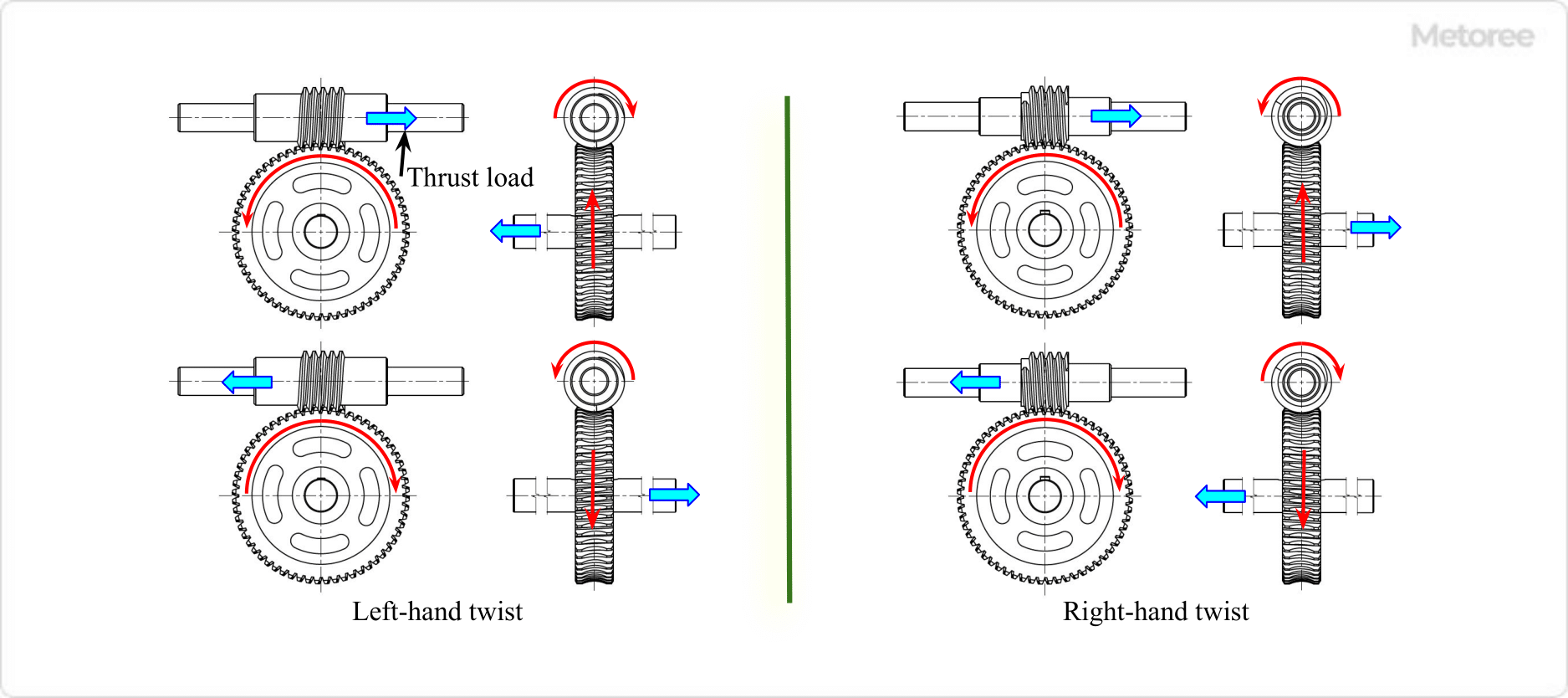
Figure 3. Direction of rotation and torsion of worm gear, direction of thrust load

Figure 3. Direction of rotation and torsion of worm gear, direction of thrust load

Worm wheels are helical gears that fit into a helical groove machined into the worm (worm shaft). This is called a helical gear,  and is one of the cylindrical gears with a spiral tooth trace.

The obliquely cut grooves mesh with the shape of the gears, resulting in a large amount of slippage and friction when the gears mesh with each other. Also, when rotating at high speeds, the tooth flanks become hot due to frictional heat. Therefore, it is necessary to reduce the coefficient of friction by using different materials, such as a hard metal for the worm and soft metal for the worm wheel.

In worm gears, when the worm is rotated, the worm’s spiral groove rotates. The teeth of the worm then press against the beveled teeth of the worm wheel, which transmit rotation to the worm wheel, causing it to rotate.

The worm gear can rotate in both directions (e.g., clockwise and counterclockwise when viewed from the input shaft side). This can be achieved by selecting the worm twist direction as a left-hand or a right hand twist. As the worm gear rotates, a thrust load is applied in the direction of the Worm Wheel and the center of the worm shaft. Therefore, the direction of the thrust load on the worm gear varies depending on the direction of rotation of the input shaft and the direction of the worm twist.

Types of Worm Wheels

1. Classification of Worm Gears by Shape

Figure 4. Shape of worm gear

Figure 4. Shape of worm gear

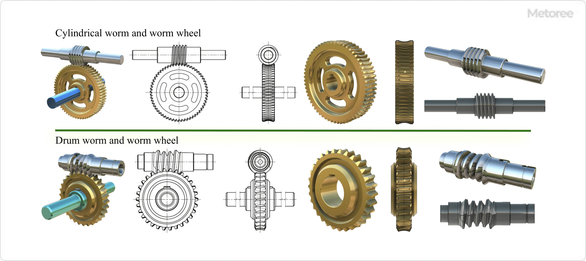
Worm gears are classified into the above types according to the shape of the worm and worm wheel.

Cylindrical Worm and Worm Wheel
Used in most cases, tooth flanks are in linear contact with each other, and transmission capability is medium.

Drum-Shaped Worms and Worm Wheels
They have a special shape that requires a high degree of manufacturing precision, and their tooth flanks are in contact with each other, resulting in a high transmission capacity.

2. Number of Worm Gear Teeth

Figure 5. 1- and 2-strip worm gear

Figure 5. 1- and 2-strip worm gear

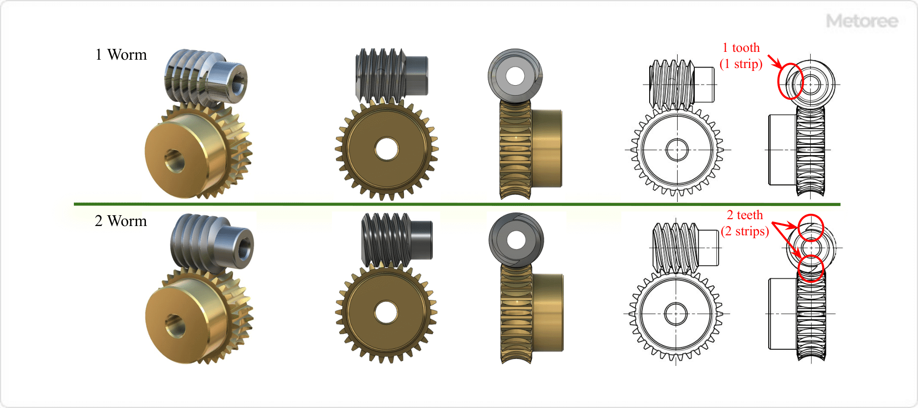
The number of worm gear teeth indicates the number of teeth on the worm (worm shaft), which can be confirmed by looking at the worm end face and checking the number of teeth per circumference of the shaft.

The number of worm teeth and their characteristics are as follows:

Single-Start
The worm has one tooth, and the worm wheel has the same number of teeth. The worm wheel rotates by one tooth per worm revolution. Reduction ratio is relatively low and torque transmission is stable.

Multi-Start
The worm has multiple teeth, and the worm wheel has the same number of teeth. The worm wheel rotates two teeth per worm revolution. The reduction ratio is greater than that of a single worm, allowing for greater torque transmission, but reducing the possibility of self-locking.

カテゴリー
category_usa

Watchdog Timer

What Is a Watchdog Timer?

A Watchdog Timer (WDT) is an electronic circuit designed to monitor and respond to malfunctioning or abnormal behavior in programmable devices like microcontrollers. It serves as a fail-safe by issuing an interrupt signal to reset the system in case of irregular operations.

Applications of Watchdog Timers

WDTs are widely used in various devices controlled by microcontrollers, including digital gadgets like smartphones, home appliances, industrial robots, and automobiles. These devices operate on predefined programs, which, despite thorough debugging, can sometimes behave unpredictably due to unexpected errors or peripheral malfunctions. In critical systems, such as those in vehicles and aircraft, WDTs are crucial for preventing serious accidents by ensuring prompt system resets.

Principle of Watchdog Timers

The WDT works by continuously counting a preset time interval. If it receives a reset signal from the CPU within this interval, it restarts the count. However, if no reset signal is received within the specified time, it assumes an abnormal state and triggers an interrupt to reset the microcontroller. This mechanism helps in detecting system malfunctions, especially when a program deviates from its intended operational state.

Some WDTs also offer adjustable timing settings through external capacitance, providing flexibility in monitoring system performance.

How to Select a Watchdog Timer

While most microcontrollers come with built-in WDTs, external WDTs are recommended for systems requiring higher reliability. This is because built-in WDTs might not detect abnormalities occurring before their activation. External WDTs are especially important in safety-critical systems like aircraft to provide an additional layer of fail-safe operation.

Other Information on Watchdog Timers

Operation Modes of Watchdog Timer

WDTs offer different operation modes to cater to various system requirements:

  • Timeout Mode: The standard mode where an interrupt signal is output if no reset signal is received within a set period.
  • Window Mode: An advanced mode that detects abnormal conditions like infinite loops by setting both upper and lower time limits for reset signal reception.
  • Q&A Mode: In this mode, the WDT checks for specific data from the microcontroller, allowing for precise detection of anomalies, though it requires more complex programming.
カテゴリー
category_usa

Aluminum Frame

What Are Aluminum Frames?

Aluminum Frames

Aluminum frames are composed of aluminum alloy materials and accessories, standardized by manufacturers for easy assembly into desired configurations. These frames come in a vast array of sizes and feature hollow rectangular shapes with T-shaped grooves on each side for attaching components, making them lightweight, strong, and versatile.

Uses of Aluminum Frames

Aluminum frames are commonly used in the research and development sectors of companies and universities, facilitating the installation of equipment and machinery. Their versatility makes them ideal for original designs where aesthetics are secondary, as well as creating light yet robust structures for DIY projects.

Principles of Aluminum Frames

Aluminum frames utilize alloys, such as the AL-Mg-Si alloy A6005C-T5, which undergoes T5 heat treatment to enhance strength and corrosion resistance. Anodizing further improves their durability and appearance. The hollow rectangular design optimizes weight, strength, and ease of attachment, with stress distribution considered to maximize structural integrity and reduce costs.

Additional Information on Aluminum Frames

Strength of Aluminum Frames

The strength and rigidity of aluminum frames are influenced by the material’s physical properties and the structure’s design. Tensile strength, yield point, and Young’s modulus are key factors, with the frame’s geometry further enhancing its load-bearing capacity. The hollow design and strategic cross-sectional shapes contribute to the frames’ effectiveness, supported by manufacturers’ data and design software for precise engineering.

Connecting Aluminum Frames

Aluminum frames are connected using bolts, nuts, brackets, and specialized joints, with brackets being the most common method. These connections ensure robust assembly, and the addition of casters can enhance mobility, facilitating the adaptation of the frames to various applications and environments.

カテゴリー
category_usa

Adapter Nut

What Is an Adapter Nut?

Adapter nuts are specialized components used in conjunction with adapter sleeves and lock washers, collectively known as adapters. These components are essential in the installation and maintenance of spherical ball bearings and spherical roller bearings, particularly those with tapered bores in their inner rings. Adapter nuts facilitate easy mounting, dismounting, and securing of these bearings.

These nuts, often synonymous with bearing nuts and lock nuts, feature a female thread on the inside diameter. The outside diameter is designed with 4 to 8 notches evenly spaced around the circumference, allowing for the use of specialized tools for tightening and loosening.

Uses of Adapter Nuts

Adapter nuts are primarily used for securing the inner rings of spherical ball bearings and spherical roller bearings onto shafts. They are crucial in ensuring these bearings are fixed in position, which is particularly important in applications such as angular contact ball bearings. Here, adapter nuts, along with lock washers, are used to firmly attach the bearings to the shaft. Tightening and adjustments are typically done using a wrench with a special hook or a socket tool designed to fit the nut’s notches.

Principle of the Adapter Nut

The Adapter Nut functions by securing the bearing to the shaft. The adapter itself has a tapered outer diameter, with a smaller hole at the side where the nut is installed and a larger hole on the opposite side. The bearing’s inner diameter also has a corresponding tapered hole. When the Adapter Nut is turned and tightened, it pushes the bearing’s inner ring inward, tightening the fit between the adapter’s outer diameter and the bearing’s inner diameter, thus securing the bearing in place. A lock washer, positioned between the adapter nut and bearing inner ring, has outer teeth that align with the notches in the adapter nut. These teeth are bent into the notches to prevent the bearing from rotating or loosening.