カテゴリー
category_usa

Surveying Instruments

What Is a Surveying Instrument?

Surveying Instruments

Surveying is the measurement of distance, height, and extent of land or objects, and surveying instruments are devices used to perform surveying.

Historically, surveying has been used since around 3000 BC in Egypt, where it was used for demarcation after the flooding of the Nile River and for the construction of pyramids. In Japan, the creation of the map of Japan by Tadataka Ino is well known.

There are various types of surveying, including reference point surveying, which determines coordinates based on a reference point, and level surveying, which determines the height of a target (sea level). Surveying instruments are also used to create maps, measure the shape and water level of rivers, and measure buildings.

Uses of Surveying Instruments

As mentioned in the previous section, there are many different types of surveying instruments, depending on the type of surveying work to be performed. Uses of surveying equipment include mapping, measuring rivers and buildings, and measuring land boundaries.

They are also used to create hazard maps for inundation and other hazards by measuring the height of the sea surface and to monitor crustal deformation, such as earthquakes and volcanic eruptions.

Principle of Surveying Instruments

Surveying instruments are used to measure distances, angles (vertical and horizontal angles), and heights (height differences).

A laser-based lightwave rangefinder is used to measure distance, while a theodolite and a scale are used to measure angles (vertical and horizontal angles). The combination of a lightwave rangefinder and theodolite is called a total station, which is widely used in surveying because it can measure oblique distances and angles simultaneously.

A single-element prism target or pin pole prism is used to measure distance, and surveying is done in pairs. There is also a non-prism type that does not use a prism. A laser beam is irradiated onto the object to be measured, and the distance is measured by the reflected laser beam.

Although performance varies depending on the model and object, distances of 500 meters or more can be measured without the use of a prism. Surveying instruments can be used with a prism in the same way as general surveying instruments.

It is characterized by the fact that it can survey even when a prism cannot be installed due to inaccessibility or inaccessibility.

It is also possible to calculate the height difference from the oblique distance and vertical angle, but the instrument height and target height must be taken into account. In addition, the longer the distance measured by a total station, the greater the error.

Another application of surveying instruments is the level, which is used for leveling. There are several types of levels, but generally, auto levels are used. Auto-levels have an automatic correction function and can keep the line-of-sight level as long as it is within the correction range.

Another method is to use the Global Navigation Satellite System (GNSS) to obtain position information. GNSS allows more efficient and quicker surveying over long distances, which is time-consuming and costly with a total station, and in locations that are difficult to survey with conventional surveying.

The use of electronic reference points also eliminates the need for reference point observations required in reference point surveying.

Surveying Regulations

There are two types of surveying: basic surveying and public surveying for which the national government or a public organization bears all or part of the cost and provides assistance.

Public surveying requires notification of the surveyor’s license.

However, some types of surveying, such as building surveying, mapping to less than 1/1,000,000, and surveying to less than the specified accuracy, do not fall under the category of public surveying and do not require notification.

Surveying instruments are also regulated. For example, the first-class theodolite must have a double angle difference of 10″ in horizontal angle and an observation difference of 5″ or less. The rangefinder also needs to be 15 mm or less in comparison to the baseline length for a Class 1 rangefinder. The total station combined with these must meet these standards for angle and distance measurements.

As described above, surveying is a highly public activity, and there are detailed regulations, so those who perform surveying must be aware of these regulations and follow the correct procedures.

カテゴリー
category_usa

Measuring Software

What Is Measuring Software?

Measuring software, also known as land surveying software, assists in determining angles and distances between points, and evaluating a 3D landscape. It is used to create maps and boundaries for buildings, or other underground public projects.

Uses of Measuring Software

Measuring software is primarily used in the design and construction of transportation networks, improving layout and construction site processes. It enhances survey team productivity by minimizing manual drawing updates, such as in the creation of ductwork layouts, reducing time and layout errors.

Principles of Measuring Software

1. Calculation Function

Measuring software efficiently registers coordinate values and supports various calculation functions, including traverse calculations and two-point narrow-angle surveying.

2. Plane, Longitudinal, and Transect Alignment Functions

It calculates plane, longitudinal, and cross-sectional alignments, and is interoperable with CAD. This functionality is efficient for road and river route calculations, as well as 3D edge calculations.

Linking longitudinal alignment with plane alignment enables 3D tension simulations in various situations.

3. Display Function

Calculation results can be visually displayed, allowing for efficient work and visualization. Measuring software enables 3D visualizations of the finished product, improving communication among construction parties and aiding in design data error prevention.

Other Information on Measuring Software

1. Traverse Surveying

Traverse surveying, a basic surveying technique, uses a sequence of measurement points from a reference point to create polygonal lines. Measuring software calculates distances and angles using prisms and devices like optical rangefinders or theodolites to determine point positions and draw floor plans.

2. Tension

Measuring software calculates building foundation heights and assists in tensioning calculations based on design values like cross-sections and structural drawings.

When calculating the tensioner, the design values are used as a guide. When calculating the hinge, the design value calculation and the hinge calculation are prepared on a separate sheet of paper, and the basis for the calculations is clarified.

3. Longitudinal and Cross-Sectional Drawings

The software outputs longitudinal and cross-sectional design drawings, such as road drawings. Longitudinal sections depict height relationships at measuring points, while cross-sections show structure configurations, aiding in road slope and width determinations.

カテゴリー
category_usa

Resistance Temperature Detectors (RTD)

What Is a Resistance Temperature Detector (RTD)?

Resistance Temperature Detectors (RTD)

Resistance temperature detectors (RTD) are used in chemical plants to measure the temperature of process fluids (liquids and gases).

Resistance temperature detectors (RTDs), however, have less measurement error than thermocouples and are more accurate, especially at low temperatures. For this reason, they are often used when low temperatures are important or when high temperatures are not measured often.

They are also widely used in temperature measurement in chemical plants because they can be used for a wide variety of fluids if a protective tube is used.

Uses of Resistance Temperature Detectors (RTD)

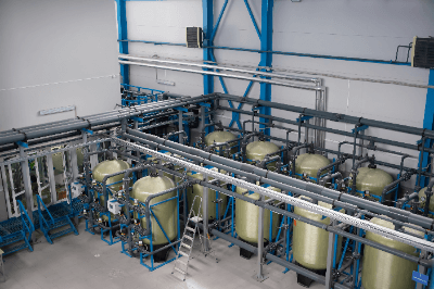
Resistance temperature detectors (RTDs) are used to measure the temperature of process fluids (liquids and gases) flowing in pipes or tanks or stored. They are often used to display temperatures, especially when they are used to control or regulate temperatures.

For example, the temperature of the cooling water at the inlet and outlet of a heat exchanger is measured to adjust the amount of cooling water according to the amount of heat exchanged. The temperature of a gas is measured when measuring the flow rate of an orifice flow meter to apply temperature compensation.

Resistance-Temperature-Detectors-RTD_測温抵抗体-1

Resistance temperature detectors (RTD) have low temperature error and high accuracy, so they can be used to control locations where the temperature is not so high or to control or regulate low-temperature antifreeze, for example.

Principle of Resistance Temperature Detectors (RTD)

Resistance temperature detectors (RTD) measure changes in temperature by utilizing the property of a metal that its resistance value changes with temperature. Metals increase their resistance value as their temperature rises, and this characteristic is used in many cases, platinum is used.

For this reason, resistance temperature detectors (RTD) made of platinum, known as Pt100, are widely used in Japan. Also, since it is common to control and regulate the temperature in industrial processes by means of a 4-20 mA current, some products have a converter built into the terminal box of the resistance temperature detector (RTD) to enable a 4-20 mA output. Such products are very convenient because they eliminate the need for a converter in the control panel.

Resistance temperature detectors (RTD) are also specified by their grade. Although these devices can measure temperatures accurately with high precision, the required accuracy varies depending on the process fluid (liquid or gas) used, so consideration must be given. However, if the thermal response is slow, it may not work well depending on the physical properties of the process fluid (liquid or gas) used, so care must be taken when performing precise control or control.

Wiring Method for Resistance Temperature Detectors (RTD)

Resistance temperature detectors can be wired in three different ways: 2-wire, 3-wire, and 4-wire. 2-wire is the simplest method, with one wire at each end of the resistance temperature detector (RTD). However, the disadvantage is that the resistance of the wiring is added as it is. Since the resistance of the wiring must be measured and corrected in advance, it is not practical.

The 3-wire method is the most common wiring method, with two wires at one end of the resistance temperature detector (RTD) and one wire at the other end, and if the electrical resistance of the three wires is equal, the resistance of the wires can be ignored. The 4-wire type is more expensive, but the resistance of the wires can be completely disregarded.

Other Information on Resistance Temperature Detectors (RTD)

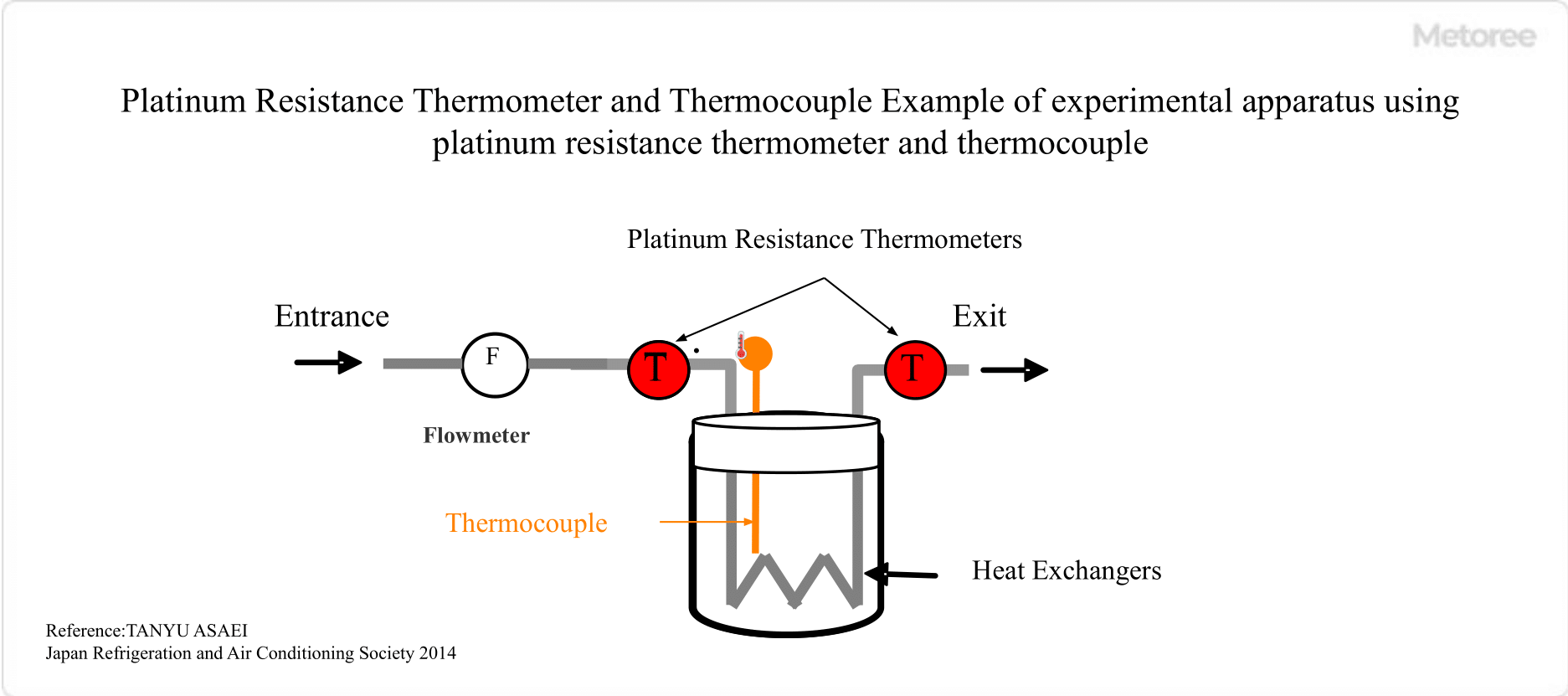
Comparison of Resistance Temperature Detector (RTD) And Thermocouple

Resistance temperature detectors (RTD) and thermocouples are both temperature measurement devices, but there are differences in temperature measurement range and accuracy.

1. Main Materials and Measuring Temperature Range

Resistance Temperature Detector (RTD)
Platinum, copper, nickel, and platinum-cobalt are available, each of which has a different temperature measurement range of up to 600°C.

Thermocouple
Platinum-rhodium alloy,” “nickel-chromium alloy,” “iron,” and “copper” are used, and their temperature measurement ranges differ. The superheat working temperature of B thermocouples is 1,700°C. For measuring high temperatures, thermocouples can be used. Thermocouples are used when measuring high temperatures.

2. Measurement Accuracy

Resistance Temperature Detector (RTD)

_Resistance-Temperature-Detectors-RTD_測温抵抗体-3-2.

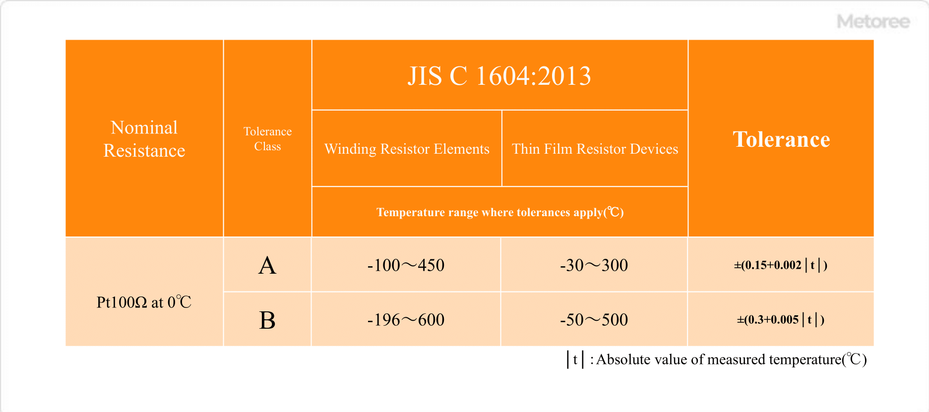
Tolerance of JIS C1604 standard for resistance thermometer

Resistance temperature detectors (RTD) are available in two measurement accuracy classes, A and B. Comparing the tolerances at 450°C, the maximum measurement temperature for Class A resistance temperature detectors (RTD), the tolerances are ±1.05 °C for Class A and ±2.55 °C for Class B.

Thermocouples

Resistance-Temperature-Detectors-RTD_測温抵抗体-3-3.

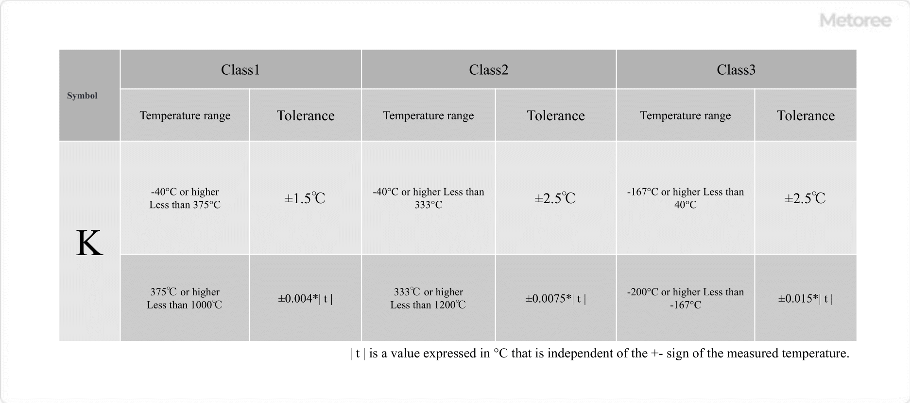
Thermocouple Temperature Tolerance

Thermocouples have measurement accuracy classes 1 to 3, which are specified for each measurement temperature range. When the thermocouple (K) is 450 °C, the tolerance is ±1.8 °C for Class 1, ±3.375 °C for Class 2, and 450 °C is not specified for Class 3. From the tolerances, it can be said that Resistance temperature detectors (RTD) have higher measurement accuracy than thermocouples, and are used for measurements that require high accuracy.

カテゴリー
category_usa

Hot Water Boiler

What Is a Hot Water Boiler?

A hot water boiler is a device that heats water by burning fuel to supply hot water. These boilers require proper treatment of exhaust gases, as well as regular maintenance, inspection, and management.

Hot water boilers come in various types and specifications, depending on the region and the size of the building. Often, specialized contractors or engineers are needed for proper maintenance.

Uses of Hot Water Boilers

Hot water boilers are used in various settings, including in heating systems and hot water supply systems in homes and buildings.

1. Heating Systems

In heating systems, hot water boilers are used for floor heating and radiators. They supply heated water to rooms, and are common in residences, offices, and hotels.

2. Supply System

Hot water boilers also supply hot water for use in faucets, showers, and bathrooms. They are essential in residential and hotel settings, providing appropriately tempered water for comfortable bathing.

Additionally, hot water boilers find applications in industries such as food processing for heating and sterilizing products, with designs varying according to process requirements.

Principles of Hot Water Boilers

A hot water boiler typically consists of a combustor, a heat exchanger, and a control unit.

1. Combustor

The combustor burns fuel, such as gas, to generate heat for heating water. It is used alongside fuel supply and combustion control equipment.

2. Heat Exchanger

The heat exchanger transfers heat between the water and combustion gases. It usually consists of metal tubes and fins, with the combustion gases passing through them to heat the water.

3. Control Unit

The control unit of a hot water boiler manages water supply, temperature control, ignition, extinguishing, and exhaust gas emission control. Some boilers also use advanced control methods to improve combustion efficiency.

Types of Hot Water Boilers

Hot water boilers are classified into four types based on the pressure inside the vessel:

1. Vacuum Type

Vacuum hot water boilers operate under negative pressure, allowing water to boil at lower temperatures. They are suitable for low-temperature heat sources and are effective in low-pressure environments.

2. Atmospheric Pressure Type

These boilers heat water under atmospheric pressure and are commonly used in homes and buildings for heating and water heating systems.

3. Hot Water Storage Type

Hot water storage boilers heat and store a fixed amount of water, suitable for applications requiring a constant hot water supply.

4. Through-Flow Type

Through-flow hot water boilers heat water instantaneously upon demand. They are energy-efficient, small, and often used in settings with irregular hot water demand.

カテゴリー
category_usa

Liquid Filling Machinery

What Is Liquid Filling Machinery?

Liquid filling machinery is a type of metered-dose filling machinery that is used to fill liquids. A metered-dose filling machine is a filling machine that can measure and fill a certain amount of liquid using a scale.

There are two types of quantitative filling machines: automatic filling machines and semi-automatic filling machines. Automatic filling machines are those in which filling containers flow through a conveyor line and start filling automatically when they reach a certain position. Semi-automatic filling machines, on the other hand, automatically flow from the conveyor line to the filling location, but the filling start operation is performed manually.

Uses of Liquid Filling Machinery

Liquid filling machinery is used by many manufacturers who produce and sell something liquid. For example, water or oil. These are filled using head pressure from a pump or tank. Liquids can also have high or low viscosity. For liquids with high viscosity, such as honey and candy, the viscosity can be lowered by increasing the temperature or by pumping.

Some liquids, such as miso and bean paste, are semi-solids but can be filled. In such cases, a screw is installed in the tank to prevent blockage.

Principle of Liquid Filling Machinery

Liquid filling machinery fills a tank or hopper. The liquid is filled from the tank or hopper through piping to the filling nozzle. When the filling process is started, the nozzle valve opens, and the liquid begins to fill. When the amount of liquid is reached, a signal is sent from the weighing device to stop filling.

The weighing instrument of the metering machine is strictly regulated. This is necessary to maintain the accuracy of filling quantities by preventing the filling of slightly smaller quantities for shipment to suppliers. Therefore, the weighing instruments used for metering machines must be certified. This is issued only after verification by a weighing organization.

Weighing instruments often use load cells. Load cells can convert the force caused by a load into an electrical signal. Load cells have a strain gauge, an electrical resistance strain gauge (sensor), attached to a metal body and measure the change in resistance. Compared to conventional spring-loaded load cells, the new load cell is much more accurate.

カテゴリー
category_usa

Liquid Dispensers

What Is a Liquid Dispenser?

Liquid dispensers are devices that dispense a fixed amount of liquid from a tank in a single motion. They are used in a wide range of industries, from manufacturing processes such as substrate processing to automatic injection systems for washing machines and disinfectants. The air syringe type uses air from a compressor or other source to push a syringe filled with a liquid to be dispensed. Tube type dispenses liquid by applying pressure to a tube that contains the liquid.

Uses of Liquid Dispensers

Liquid dispensers are used in a variety of industries, including semiconductor, display, automotive, and battery manufacturing plants, toilets, washing machines, and automatic disinfectant injection systems. In semiconductors, displays, and batteries, they supply the liquid materials used; in automobiles, they supply paints and preservatives; and in toilets and washing machines, they supply detergents and disinfectants. When selecting a liquid dispenser, it is necessary to consider whether it is compatible with the liquid to be supplied, the accuracy of the volume to be dispensed, and the size of the volume to be dispensed.

Principle of Liquid Dispensers

The following is a description of the principle of operation of liquid dispensers, divided into air syringe type, volumetric type, and tubular type.

1. Air Syringe Type

The air syringe type consists of a syringe containing the liquid to be dispensed, a compressor, an open valve, and a control panel. During operation, the compressor increases the pressure and the release valve releases it, pushing the syringe under pressure and dispensing the liquid in the syringe. When the volume to be dispensed reaches the input value, the valve is closed by the control panel to stop dispensing.

2. Volumetric Type

The positive displacement type consists of a container containing the object to be dispensed and a positive displacement pump inside the container. During operation, the rotation of the motor activates the positive displacement pump, which pushes the fluid to be discharged.

3. Tube Type

The tubular type consists of a tube containing the fluid to be discharged and a compressor or other device to which pressure is applied. During operation, pressure is applied to the tube to dispense the fluid from the tube.

カテゴリー
category_usa

Purification Systems

What Is a Purification System?

Purification Systems

A purification system is a device that removes undesirable substances from gases and liquids to prevent them from escaping to the next process or outside or to maintain or improve the environment itself.

There are various types of purification systems. For example, some systems physically remove target substances by collecting and adsorbing them with a filter or similar device. Other types include those that decompose target substances by inducing them into a high-temperature environment or an environment where a catalyst exists and those that detoxify target substances by supplying substances such as photocatalysts with sterilizing or oxidizing effects.

Applications of Purification Systems

Purification systems are often used to purify liquids or gases. The most common purification systems used to purify liquids are those used for household and commercial water treatment. The most familiar examples are water purifiers and water tank filters, which collect undesirable substances and add disinfectants as needed to maintain water quality.

Another typical example of a purification system used to purify gases is an automobile exhaust gas purification system. In the purification system for automobile exhaust, harmful substances generated when fuel is burned are decomposed into harmless substances under the presence of a catalyst. This purification system allows the harmless exhaust to be discharged into the atmosphere, thereby preventing any impact on the atmosphere.

Principle of Purification Systems

The principle of the purification system depends on the purification mechanism. Here, we will explain the Purification System used for water purification and the gas purification system used for the purification of automobile exhaust gases.

1. Water Purification System Using Activated Carbon Filters

The purification system used for water purification generally uses a filter made of activated carbon to purify water. When water is passed through an activated carbon filter, particles of undesirable substances in the water are adsorbed on the surface of the activated carbon due to the gravitational force (van der Waals force) from the surface of the activated carbon. The adsorbed particles are drawn into the pores of the activated carbon surface by capillary action, thus purifying the water.

In the case of this purification system, the fineness of the filter made of activated carbon can be adjusted by adjusting the size of the pores on the surface of the activated carbon. Therefore, if the particle size of the substance to be collected is known, the type of substance to be collected can be changed by setting the fineness of the filter as desired. 

2. Water Purification System Using Ion Exchange Membrane

In the production of pure water, it is necessary to remove salt components such as calcium, sodium, and chloride from the water. These salt components exist in water as ions. Therefore, positively or negatively charged ion exchange membranes can be used as filters to adsorb and remove cations or anions for purification.

Whether using activated carbon filters or ion-exchange membranes, the contact area of the liquid is increased to improve adsorption efficiency.

3. Gas Purification System

Purification systems used to purify automobile exhaust gases, for example, utilize a catalyst. In a purification system using a catalyst, the target liquid or gas is brought into contact with the catalyst to render it harmless. In an automobile exhaust gas purification system, gases generated by combustion are introduced under a three-way catalyst to oxidize CO, which is a harmful component, to CO2 and hydrocarbons to CO2 and H2O, while NOx is reduced to N2 and O2 to render it harmless.

Even when a catalyst is used, it is necessary to devise a way to increase the contact area of the gases to improve the efficiency of the reaction.

Other Information on Purification Systems

1. Purification System for Water Tanks

One of the most familiar purification systems around us is the aquarium purification system. It is an indispensable equipment for aquariums that keep tropical fish and other aquatic organisms. There are three main methods of aquarium purification

Physical Filtration
Physical filtration captures tropical fish feces, food scraps, dead and decomposed aquatic plants, and other debris with a net, sponge, or other large-mesh material. The goal is to remove enough debris to be visible.

Chemical Filtration
Chemical filtration removes invisible debris from the water using materials such as ion exchange resins, zeolite, and activated carbon. These materials have microscopic holes in them that absorb debris and remove it from the water.

Biofiltration
In biological filtration, bacteria and other microorganisms work to decompose organic and toxic substances in the water and clean the water. It is an especially important filtration method for aquariums because it detoxifies highly toxic ammonia and nitrite, which cannot be removed by physical or chemical filtration.

2. How to Make Your Purification System

This section describes a homemade water purification system that can be made with items that are available around you. However, although this purification system can purify water, it is not potable water and should not be drunk. You will need the following materials

  • Empty plastic bottles (about 2 liters)
  • Cloth (hand towel, etc.)
  • Tissue
  • Pebbles, jari, activated charcoal, sand

The purification system removes small debris gradually from large debris in a process of purification. Therefore, hollow out the bottom of the PET bottle with the cap on, cap side down, and put in the materials from the top in the following order.

  • Tissue
  • Pebbles
  • Gravel
  • Activated charcoal
  • Sand
  • Cloth

In other words, from the cap side, they are stacked in the following order: tissue, pebbles, gravel, activated charcoal, sand, and cloth. Purification is done by removing the cap and slowly pouring muddy water from the bottom of the hollowed-out PET bottle. Then, impurities are collected by the materials inside in order of size, and the purified water slowly flows out from the mouth.

カテゴリー
category_usa

Detergents

What Is a Detergent?

Detergents

Detergent is a general term for chemicals used to purify soil and water.

Detergents used for water in particular include coagulants. When a coagulant is used to treat polluted raw water, it collects and solidifies the pollutants and separates the water from the pollutants.

Detergents are used to obtain clean water.

Applications of Detergents

Water detergents are substances used to purify rivers, industrial and agricultural wastewater, and industrial water, and to improve water quality in livestock and aquaculture farms. In particular, they are used to remove contaminants such as heavy metal powders and organic matter in industrial wastewater. These products are also used for other purposes such as the prevention of bad odors.

Soil detergents include those that adsorb and purify harmful substances such as pesticides, PCBs, dioxins, and heavy metals, and those that activate microorganisms in the soil to break down pollution and produce nutrients that are good for plants.

Principle of Detergents

Detergents purify pollutants in a wide variety of ways, depending on the product. Each uses the effects of microorganisms, chemical reactions, charcoal, and other properties.

1. Coagulant

A coagulant is a substance that coagulates colloidal particles suspended in water. Water detergent treatment with flocculants is divided into the following two major processes.

  1. Coagulation reaction to precipitate fine flocs called foundation flocs
  2. Coagulation reaction in which the basic floc grows and coarsens

Since fine particles existing in nature are generally negatively charged, substances generally used as flocculants are those with positive charges. Specifically, they are inorganic flocculants such as aluminum salts and polyiron chloride. When a coagulant is added, the charge is neutralized and coagulation occurs, resulting in small clumps called foundation flocs.

In wastewater treatment, coagulants (polymers) are used to coagulate the flocs, while poly aluminum chloride (PAC) is mainly used in water treatment. Polymer flocculants are generally not used in wastewater treatment. This is because residual polymer flocculants can cause organic contamination of ion exchange and reverse osmosis equipment. After encouraging sedimentation of pollutants, clean water is obtained by solid-liquid separation.

2. Porous and Chelating Agents

Zeolite and charcoal with porous properties are effective in adsorbing harmful substances, precious metals, and odor-causing substances. Artificial zeolites also have a high cation exchange function and can improve soil by neutralizing acidity and removing ammonium ions from sewage and wastewater. Because of its strong fertilizer retention, it can be used as a soil detergent to improve the growth of crops and to cultivate high-value-added crops.

In the method using a chelating agent, metal ions in an aqueous solution react with the chelating agent to form a complex that is insoluble in water, thereby removing the ions. By using a chelating agent that selectively binds to heavy metals, it is possible to remove mercury, cadmium, lead, chromium, etc.

3. Microorganisms

Aerobic microorganisms can be used to absorb and decompose organic matter such as VOCs through the power of microorganisms in the water or indigenous to the area. Substances that activate the decomposition action of microorganisms, such as natural minerals, and microbial preparations fall under this category. This method is clean and harmless to the natural environment as it does not use chemical substances.

Types of Detergents

Types of detergents include the following

  • Coagulants that precipitate substances cause pollution by coagulation reaction
  • Porous materials that adsorb harmful substances
  • Microorganisms that activate microorganisms to promote the decomposition of substances causing pollution

Each method has different principles and types of pollution that can be purified, so it is necessary to select the one that best suits the purpose. In addition, the water purification method to be used differs between wastewater purification and water purification. Since there are powder, granular, gel, and other forms available, it is important to select the most appropriate formulation.

カテゴリー
category_usa

Hydraulic Equipment

What Is Hydraulic Equipment?

Hydraulic equipment is a device that uses hydraulic pressure to convert or transmit power into motive force.

Specifically, a hydraulic pump is driven by an electric motor or an engine, and the pressure obtained from the pump is used to operate a hydraulic cylinder or a hydraulic motor. Hydraulic equipment provides a large output with a small input, saves space, and has excellent durability against high temperatures.

Because of these features, hydraulic systems are used in a wide range of products, such as large vehicles and industrial machinery, and are products that support industry.

Applications of Hydraulic Equipment

Hydraulic equipment is used in a wide range of applications, from vehicles to machine tools.

1. Vehicle-Related

In the vehicle industry, hydraulic systems are mainly used in large vehicles. This is because they can perform tasks that require large amounts of power with small amounts of power.

2. Industrial Machinery

Hydraulic equipment is also utilized in many manufacturing fields.

Principle of Hydraulic Equipment

Hydraulic equipment utilizes Pascal’s Principle, which states that a stationary fluid transmits the same pressure in any direction. Pascal’s principle means that when the cross-sectional area of a pipe is different, the force required to maintain pressure is inversely proportional to the cross-sectional area.

As an example, the following case is explained.

  • Pressure: 1.0 MPa
  • The cross-sectional area of the input side: 10 cm2
  • The cross-sectional area of the output side: 100 cm2

In this case, the following forces are required to maintain the same pressure.

  • Force required at input: 100 kg
  • Force to be output:1,000kg

As described above, by utilizing Pascal’s principle, a large output can be obtained with a small input. Hydraulic equipment is, of course, also utilized in automobile brakes and hydraulic jacks.

The mechanism of hydraulic equipment is as follows.

  1. Power from an engine or other source is used to provide rotational force to the hydraulic pump.
  2. Pressure is generated in the oil discharged from the hydraulic pump.
  3. The pressurized oil is controlled by the hydraulic equipment and then transmitted to the hydraulic cylinders and motors.
  4. Hydraulic cylinders and motors convert fluid energy into kinetic energy.

At this point, linear motion can be converted by the hydraulic cylinder and rotational motion can be converted by the hydraulic motor. The oil drained by the hydraulic equipment returns to the oil tank. And when energy is needed again, it is discharged again from the hydraulic pump.

Structure of Hydraulic Equipment

Hydraulic equipment is composed of the following three components, a hydraulic oil tank, pressure gauges and other auxiliary equipment, fittings, and hydraulic hoses.

  • Hydraulic Equipment
    Hydraulic equipment that generates energy to be added to the oil (mainly the hydraulic pump)
  • Hydraulic Equipment Hydraulic Drive Equipment
    Hydraulic equipment that converts the pressurized oil delivered from the pump into power (hydraulic cylinders, hydraulic motors, vane motors, plunger motors)
  • Hydraulic Equipment
    Hydraulic equipment that controls the pressure and flow rate discharged from the hydraulic pump (relief valve, directional control valve, flow control valve)

In addition, there are four types of hydraulic pumps

  • Gear Pump
    Pumps that utilize the meshing parts of gears to transport
  • Vane Pump
    Pumps that use several plates to change the volume and transport the fluid.
  • Piston Pump
    A pump that changes the volume of a cylinder by reciprocating a piston to convey.
  • Screw Pump
    Pumps that transport by utilizing the rotation of a screw.

Other Information on Hydraulic Equipment

1. Advantages of Hydraulic Equipment

  • Simple structure compared to mechanical or electric
  • Compact and powerful force can be obtained
  • Can be controlled by simply changing the supply flow rate to the cylinder, so no transmission is required
  • The relief valve prevents overloading
  • Energy can be stored
  • Low vibration
  • High-temperature resistance and durability

The appeal of hydraulic equipment is that it can be used in a wide range of environments, including confined spaces and high temperatures.

2. Demerits of Hydraulic Equipment

  • Prone to oil leaks and vulnerable to rust and debris
  • Need to control hydraulic oil for contamination or deterioration
  • Machine efficiency varies depending on the temperature of the hydraulic oil

If hydraulic equipment is to be installed, oil maintenance is essential. To prevent accidents, it is necessary to prepare manuals on inspection frequency and methods.

カテゴリー
category_usa

Hydraulic Nuts

What Is a Hydraulic Nut?

Hydraulic Nuts

A hydraulic nut is a nut that is fastened by an axial force generated by hydraulic pressure, not by a screw.

The fastening force between a bolt and nut with a screw is generated by pulling up the axis of the screw using the screw’s helix. Hydraulic nut, on the other hand, uses hydraulic pressure to pull the bolt to generate the fastening force. As is the case with bolts that use screws, the nut can be subjected to torsion due to the frictional force of the screw, and variations in axial force can be suppressed.

No tightening tool is required because the bolt is pulled and fastened by a component that has a hydraulic function in the nut itself. The hydraulic nut is set on the bolt and a hose connected to a hydraulic pump is connected to the hydraulic nut supply port. By attaching the hose, multiple nuts can be tightened simultaneously. When hydraulic pressure is applied, oil is fed into the hydraulic nut, and the bolt is pulled to tighten.

A hydraulic nut uses a nonflammable glycol fluid instead of oil to provide the hydraulic function. The difference between a hydraulic nut and a bolt tensioner is that a hydraulic nut acts as a nut, whereas a bolt tensioner is set on the bolt and nut and removed after tightening, so it does not remain in place like a hydraulic nut.

Uses of Hydraulic Nuts

Hydraulic nuts are used in fastening relatively large-size bolts. The screws used are in the range of M20~300.

They are also used for mold fixing bolts for molding presses and injection molding machines and for the temporary fastening of large bolts on the mating surfaces of gas turbine and steam turbine casings for thermal power generation.

Principle of Hydraulic Nuts

A hydraulic nut uses hydraulic pressure to pull the bolt and generate an axial force on the bolt. Hydraulic pressure is based on Pascal’s principle, which states that when a certain force is applied to a sealed container of liquid, the pressure acts perpendicular to the surface of the container equally in all directions without reducing the volume.

The hydraulic nut allows the bolt to continue to generate the axial force on the bolt even after the hydraulic pressure is removed by allowing the nut to sit on the object to be fastened while the bolt is being pulled by the hydraulic pressure. When axial force is generated by an ordinary screw, the bolt will break at a lower axial force than simple tension because the friction of the threaded surface and the seating surface of the bolt’s head will cause the bolt to twist.

In addition, the frictional force of the screw and seat surface is variable, and when combined with the variation in tightening torque, there is typically a very large variation in axial force. With hydraulic nuts, the bolt is not subjected to torsion and the exact axial force can be determined from the hydraulic pressure.

Additional Information on Hydraulic Nuts

Advantages of Hydraulic Nuts

Hydraulic nuts can be used in tight places where a hydraulic torque wrench or bolt tensioner would have difficulty. Hydraulic nut is also suitable for tightening many bolts at the same time and evenly in other tight places where tools cannot enter. Tightening work is possible even in places with complicated shapes or where it is difficult for tools to enter if a hydraulic hose can be attached. Hydraulic nut is also suitable for tightening where the base shifts when the nut is tightened since there is no twisting power.

Compared to a hydraulic torque wrench, which controls torque, the hydraulic nut can be tightened more precisely without being affected by friction. By attaching a hose, multiple nuts can be tightened at the same time, thus eliminating variations in bolt tightening. Another advantage is that it prevents one-sided tightening of flanges and eliminates the need for diagonal tightening, thereby increasing work efficiency.

Hydraulic nuts are also useful when frequent and precise fastening and unfastening of multiple bolts and nuts is required, when loosening due to vibration is a concern, and in high-temperature locations. They are used in nuclear power plants because they are efficient and can be used at high temperatures, thus contributing to reduced worker exposure.

Unlike hydraulic torque wrenches used for manual tightening and torque management, this wrench does not twist the bolt and applies axial force directly, so there is no friction when tightening and highly accurate axial force management is possible. Also, since the bolt is not twisted, frictional heat is not generated, and there is no burning of the flange or threaded parts.