カテゴリー
category_usa

Film Thickness Meters

What Is a Film Thickness Meter?

Film Thickness MetersA film thickness meter is a device that measures the minute thickness of an object.

For example, it is used to examine thin films that are difficult to measure visually, such as the thickness of paint film or metal plating. There are several types of film thickness meters, and the measurement method is selected according to whether the object to be measured is light-transparent or not, and whether the measurement is done by contact or non-contact.

Uses of Film Thickness Meters

Film thickness meters are mainly used to measure the thickness of painted surfaces. Paint is applied to many everyday items such as home appliances, automobiles, etc., to maintain their durability as well as to maintain their aesthetics.

The thickness of the paint film must be appropriate and uniform. If the film thickness is not appropriate, i.e., if it is too thick, cracks may occur. If it is too thin, discoloration, loss of luster and deterioration of the substrate may occur. If the coating is not uniform, the durability may vary from place to place, making it impossible to maintain quality.

Therefore, a common method of quality control is to use film thickness meters to measure and control the thickness of the coated film on various items. There are various types of film thickness meters, and the appropriate device is used depending on the object to be measured. For example, when measuring the thickness of a transparent thin film, a spectral interferometer that uses a broadband light beam or an infrared film thickness meter that uses infrared light is used.

However, these methods cannot be used for metals because they do not allow light to pass through. When measuring metal plated thin films, electromagnetic film thickness meters that use changes in magnetic flux or eddy-current film thickness meters that use eddy-currents are suitable. In addition, non-contact film thickness meters, such as ultrasonic film thickness meters, are also used when it is difficult to make contact with the object to be measured.

Principle of Film Thickness Meters

Film thickness meters are available in a variety of measuring methods, and the appropriate device is used depending on the object to be measured. The following five methods are typical.

1. Spectral Interferometry Film Thickness Meter

This is a film thickness meter that uses light interference. When light is incident on the object to be measured, light is reflected from the surface and the back of the thin film. These two reflected beams have a phase shift, and the shift is proportional to the thickness of the thin film. Waves are strengthened when they overlap in the same phase and weakened when they overlap in the opposite phase, making it possible to measure thickness by measuring the difference in interference.

2. Infrared Film Thickness Meter

This film thickness meter utilizes the absorption of infrared rays by the object to be measured. When an object is irradiated with infrared rays, certain wavelengths of infrared rays are absorbed depending on the material and thickness of the object to be measured. This property is used to measure the film thickness based on the spectrum obtained by spectroscopy of the transmitted or reflected light. If the relationship between the absorption rate of the material to be measured and the film thickness is measured in advance, the film thickness can be calculated.

3. Electromagnetic Film Thickness Meter

This is a film thickness meter that utilizes changes in magnetic flux density. This measurement method is used when the object to be measured is formed on a metallic surface with magnetism, and utilizes the fact that the magnetic flux density changes when a magnet is brought close to the metal only or when a magnet is brought close to the object to be measured while it is on the metal. However, this method can only be used when the object to be measured is in contact with metal and the object is not metal.

4. Eddy-Current Film Thickness Meter

The eddy-current film thickness meter uses the change in magnetic flux generated by a coil to measure the thickness of the object to be measured. When the coil is energized, magnetic flux is generated around the coil, and when the coil is brought close to the object to be measured, the magnetic flux changes according to the thickness of the object to be measured. The thickness of the object is measured by detecting this change in magnetic flux.

5. Ultrasonic Film Thickness Meter

An ultrasonic film thickness meter is a film thickness meter that utilizes the reflection of ultrasonic waves. When ultrasonic waves are emitted from the surface of the object to be measured, they pass through the interior of the object to be measured and are reflected on the reverse side. The thickness can be measured from the time it takes for this reflection to occur.

For example, when measuring the thickness of a transparent thin film such as glass, a spectral interference film thickness meter using a broadband light beam or an infrared film thickness meter using infrared light is used. On the other hand, these film thickness meters cannot be used for thin films that do not transmit light, such as metals.

When measuring thin films of metal plating, electromagnetic film thickness meters that use changes in magnetic flux or eddy-current film thickness meters that use eddy-currents are used. In addition, non-contact film thickness meters, such as ultrasonic film thickness meters, are also used when it is difficult to make contact with the object to be measured.

Types of Film Thickness Meters

Film thickness meters can be classified into three types: contact, non-contact, and cross-sectional observation.

1. Contact Film Thickness Meter

In contact-type film thickness meters, the sensor part is connected to the main body of the meter by a cable, and the sensor part is brought into contact with the object to measure the film thickness. Contact-type film thickness meters include the electromagnetic induction type, overcurrent type, ultrasonic type, and stylus type. The most orthodox type of film thickness meter can be purchased for several tens of thousands to 200,000 yen, depending on its performance.

Using a contact-type film thickness meter is simple; just place the sensor part against the substance to be measured, and a numerical value will be displayed. However, since the reaction speed varies depending on the substance, you may have to wait a few seconds for the sensor to react. Among contact-type film thickness meters, the electromagnetic induction type and the overcurrent type must be used depending on the substrate on which the measurement is to be made.

The electromagnetic induction type is used for magnetic materials such as iron and steel, while the overcurrent type is used for nonmagnetic materials such as aluminum and stainless steel. Dual types that measure with both methods are also available. The dual type can measure both magnetic and non-magnetic materials.

2. Non-Contact Film Thickness Meter

Non-contact film thickness meters emit light from the body of the meter and measure film thickness by detecting the interference of wavelengths of light reflected from the surface of the film and penetrating into the film as a spectrum. Basically, this form is used in places inaccessible to the human hand. Reflectance spectrophotometer, infrared spectrophotometer, capacitance spectrophotometer, and radiation spectrophotometer are available. Since a high-precision semiconductor device is used for the detection part, the price is higher than that of the contact type.

3. Cross-Sectional Observation Type Film Thickness Meter

Cross-sectional film thickness meters are electron microscopes such as TEM and SEM. They are used to measure extremely small materials that cannot be measured with contact or non-contact methods. However, they are often used in research and technological development and are rarely employed in the field.

カテゴリー
category_usa

Defoamers

What Is a Defoamer?

Defoamers are devices used to remove gas (bubbles) from liquids. They are used in the production process of various products, ranging from low-viscosity liquids such as water and chemical solutions to high-viscosity liquids such as resins and oils.

Defoamers are available in various forms depending on the liquid used and the uses of the product. In addition to vacuum (decompression), pressurization, and centrifugal force, defoamers using ultrasonic waves and gas-permeable membranes are also available.

By removing air bubbles from liquids, the strength, properties, and surface characteristics of products can be made uniform, thereby improving product yield and quality.

Uses of Defoamers

Vacuum defoamers are most commonly used to defoam by reducing pressure. Because bubbles can be expelled into decompressed air over time, even in liquids of high viscosity, vacuum defoamers are used to defoam silicone rubber and various resins. Sometimes, additives called defoamers are used in combination to help break up the foam film that has reached the surface of the liquid.

Pressurized de-aerators use pressure to compress bubbles temporarily to a very small size. When the pressure is released, the bubbles return to their original size, so they are used for materials such as thermosetting resins and glues for adhesive tapes, where the size of the bubbles is fixed when the product is made.

Principle of Defoamers

Vacuum defoamers use a vacuum pump to depressurize a sealed container containing a sample, causing the bubbles in the liquid to expand. The expanded bubbles float to the surface of the liquid due to buoyancy. Then, they are discharged into the depressurized air as the liquid film on the surface is destroyed over time. Although this method is useful for liquids with high viscosity, it is important to note that decompression may cause the liquid to boil at room temperature. The rapid decompression causes the temperature of the gas to drop due to Boyle-Charles’ law, and the higher the clay content of the liquid, the longer it takes to defoam the sample.

Centrifugal defoamers utilize the principle of separation of liquid and gas with density difference due to the centrifugal force generated when the container containing the sample rotates on its axis and revolves on its axis. Depending on the model, centrifugal deaerators can generate acceleration 100 times greater than the acceleration of gravity.

Vacuum defoamers and centrifugal defoamers are sometimes used together. In this case, the centrifugal force separates the bubbles, whose density has greatly decreased due to expansion caused by decompression, from the liquid, resulting in a more powerful defoaming action.

カテゴリー
category_usa

Pressure Testers

What Is a Pressure Tester?

Pressure testers are used to check whether various types of equipment, such as home appliances, have dielectric strength when high voltage is applied to them.

If the equipment does not have dielectric strength and dielectric breakdown occurs when high voltage is applied, the user may be electrocuted or disabled. As well, a fire may occur, or in the worst case, the equipment may explode.

To avoid such a situation, the laws stipulate the withstand voltage that must be observed for each device.

Pressure testers are used to test whether the equipment meets the withstand voltage standards.

Uses of Pressure Testers

If a person touches a device that has suffered a dielectric breakdown, a path is created for an electric current to flow through the device. The current flows from the device to the earth via the human body and can cause a person to receive an electric shock.

A countermeasure against electric shock is to insulate the equipment completely so that the current does not flow out of the equipment to the outside. Another method is to provide a current path with a resistance value as close to zero as possible in case the current flows out of the equipment. Generally, these measures are taken at the equipment design stage.

As a result of the design, the equipment is tested using a pressure tester to see if it has the insulation to withstand voltage as designed.

Principle of Pressure Testers

Pressure tester testing is performed by applying an AC or DC voltage of several kilovolts, which is several tens of times the voltage normally handled.

Specifically, a short circuit is made between two power supply terminals and a high voltage is applied for a certain period between the terminals and the exterior of the equipment, such as the housing or cabinet.

Equipment operation is checked after the application of high voltage, and the equipment passes the test if the same level of operation can be confirmed as before the test.

Pressure testers are required to conduct tests in accordance with safety and other laws to confirm that equipment meets the standards, so accurate testing is necessary. The test is meaningless unless the applied voltage value and the applied time are accurate.

For this reason, pressure testers must be calibrated periodically. This involves preparing a standard device that has been verified to show correct values, checking to see if there are any deviations in the values shown by the testing device compared to the standard device, and making adjustments. Generally, a sticker with the date of calibration is attached to the calibrated tester to ensure correct management of the equipment.

カテゴリー
category_usa

Insulating Paint

What Is an Insulating Paint?

Insulating paint is a special type of paint designed to provide electrical insulation. Made from highly insulating raw materials such as natural resins, synthetic resins, oils, and fats, it is used to prevent electrical accidents by insulating conductive parts. Insulating paints are notable for their heat and chemical resistance and are crucial in electrical products to prevent personal injury and malfunctions by insulating electricity flow.

Application of insulating paint requires knowledge and skill, including adherence to correct methods and drying times, to ensure effective insulation.

Uses of Insulating Paint

Insulating paints are used in various sectors, particularly where electricity is used, such as in electrical products and home appliances:

1. Electrical Products

Used to insulate circuits in electronic equipment like PCs, preventing electrical shorts and enhancing reliability.

2. Home Appliances

Applied in appliances like TVs and refrigerators for insulating electrical wiring and improving safety.

3. Automotive Industry

Used in vehicles for insulating electrical systems and wiring harnesses, ensuring electronic system reliability.

Principle of Insulating Paint

Insulating paints function both as insulators and surface protectors:

1. Providing Insulation

Made of polymers or rubber-based materials, they inhibit electrical charge transfer, offering insulation.

2. Surface Protection

They protect surfaces from moisture, environmental factors, and physical damage, forming a thin insulating layer upon drying or curing.

Types of Insulating Paint

Diverse types of insulating paints are available, each with unique properties:

1. Acrylic Resin Paint

Known for its transparency and gloss, used mainly for automobiles and home appliances but susceptible to UV rays.

2. Epoxy Resin Paint

Characterized by its adhesive quality and excellent water and corrosion resistance, used for pipes, tanks, and transformer coils.

3. Silicon Paint

Contains silicon, offering outstanding heat resistance, suitable for air conditioners and heaters.

4. Polyurethane Resin Paint

Made from polyurethanes, known for chemical resistance and durability, used in home appliances, communication equipment, and for surface coating of floors and furniture.

カテゴリー
category_usa

Insulated Bolt

What Is an Insulated Bolt?

An insulated bolt is a bolt that is either covered with or made from an insulating material. These bolts are typically used when electrical isolation is necessary. The insulating materials, such as plastic or rubber, prevent the passage of electricity and help avoid electrical shorts and circuit breakdowns. Insulated bolts made entirely of plastic also resist various chemicals and solutions, offering durability in corrosive environments and chemical processes.

Uses of Insulated Bolts

Insulated bolts find applications in:

1. Electrical Wiring

Used in electrical wiring for insulation between streetcars and overhead wires, or in electrical equipment like switchboards and control panels.

2. Chemical Plants

Utilized in chemical plants to prevent dissimilar metal corrosion, especially in flange connections between iron and SUS pipes.

3. Metal Electrolysis Plants

Widely used in metal electrolysis plants for safely handling metal plates with voltage, preventing sparking and electrical corrosion.

4. Electroplating Factories

Employed in electroplating factories for insulation of metal components and lifting jigs during the plating process.

Principle of Insulated Bolt

The core principle of an Insulated Bolt lies in the electrical insulating properties of its material. The non-conductive nature of materials like plastic or rubber provides effective electrical insulation, preventing current flow and electrical shorts.

Types of Insulated Bolts

Insulated bolts vary based on the type of insulating material used:

1. Plastic-Coated Bolt

A metal bolt with a plastic coating, commonly used for its insulating properties.

2. Rubber-Coated Bolt

A metal bolt coated with rubber, enhancing chemical and abrasion resistance while providing insulation.

3. Ceramic Coated Bolts

A metal bolt with a ceramic coating, suitable for high-temperature and high-voltage environments, often used in power transmission and high-voltage equipment.

カテゴリー
category_usa

Isolation Transformers

What Is an Isolation Transformer?

Isolation Transformers

An isolation transformer is a transformer in which the primary and secondary electrical circuits are not connected by conductors.

A transformer is used to change the power supply voltage. In a typical electric circuit, conductors are connected from the power source to the demand equipment. By using an isolation transformer, the conductors of the power source and the demand equipment can be separated.

Most transformers used for power supply are isolation transformers.

Uses of Isolation Transformers

Isolation transformers are used in a wide range of applications, from industrial power supplies to household power supplies.

Specific uses of isolation transformers:

  • For power conversion in power plants and substations
  • For lightning protection of office automation equipment
  • For power supply for factories and commercial facilities
  • Inside old AC adapters
  • For power transmission in general households
  • For noise reduction for semiconductor products

As mentioned above, isolation transformers are widely used for power transmission and distribution. They may also be installed for noise rejection and lightning protection.

Principle of Isolation Transformers

Isolation transformers are devices that transform and insulate using electromagnetic induction. They consist of primary and secondary windings, an iron core, and a casing.

The primary winding is the winding that receives voltage and power from the power supply. The iron core runs through the center of the winding, and the secondary winding runs through the same iron core. Because of this structure, electromagnetic induction works between the windings, and the voltage corresponding to the number of turns of the primary and secondary windings is supplied to the secondary windings.

The ratio of the number of turns of the primary and secondary windings is called the turn ratio. The more turns of the primary winding, the larger the turn ratio, the larger the turn ratio, the smaller the voltage received by the primary winding. Therefore, more power can be transmitted to the secondary winding.

Other Information on Isolation Transformers

1. Isolation Transformer and Non-isolation Transformer

Common power transformers are isolation transformers, but in rare cases, non-isolation transformers are used. Isolation transformers are transformers in which a portion of the primary winding is used for the secondary winding. Isolation transformers are also called single-winding transformers because of their construction.

Isolation transformers, on the other hand, are called double-wound transformers. Single-winding transformers are less expensive than double-winding transformers because they use less copper wire for the windings. However, since the primary side is not insulated from the secondary side, there is a risk that abnormal voltage on the primary side (e.g., lightning) will spread to the secondary side and destroy demand facilities. Single-winding transformers are used on top of overhead cranes and inside radios to reduce size.

2. Isolation Transformers and Noise

One of the purposes of using isolation transformers is to eliminate noise. However, ordinary isolation transformers can only remove low-frequency noise (common mode noise), not high-frequency noise (normal mode noise). To eliminate normal mode noise, transformers with electrostatic shielding on the primary and secondary windings are available.

As electrical equipment becomes more sophisticated and compact, circuits become closer together, and noise immunity tends to decrease. Noise introduced into electrical and electronic circuits can cause significant damage to system operation. Susceptibility to noise is a drawback of semiconductor components, which are becoming increasingly miniaturized.

Among them, controllers that control systems are less tolerant of noise due to the high integration of chips. If noise gets into such components, it can cause system malfunctions, internal data corruption, and the inability to recover data. Therefore, noise suppression measures such as the use of isolation transformers with electrostatic shielding are essential for semiconductor products.

3. Isolation Transformer and Grounding

Although the primary and secondary windings of an isolation transformer are insulated, there is a risk that the windings may become mixed up with each other in the event of an earthquake or other accident. If the windings become mixed up, there is a risk that the voltage on the high-voltage side will spread to the low-voltage side, resulting in an electric shock hazard.

For this reason, transformers of high voltage are required to have one grounding point on the low voltage side. The grounding used in this case is Class B grounding, which is connected to the low-voltage side neutral point of the isolation transformer and the anti-collision plate, etc. Applying Class B grounding to the isolation transformer makes it easier for the leakage detection equipment to detect leakage currents and also reduces the incoming voltage when there is a collision.

カテゴリー
category_usa

Ultraviolet (UV) Sterilizers

What Is an Ultraviolet (UV) Sterilizer?

Ultraviolet (UV) Sterilizers
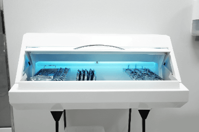
The ultraviolet (UV) sterilizer is a type of
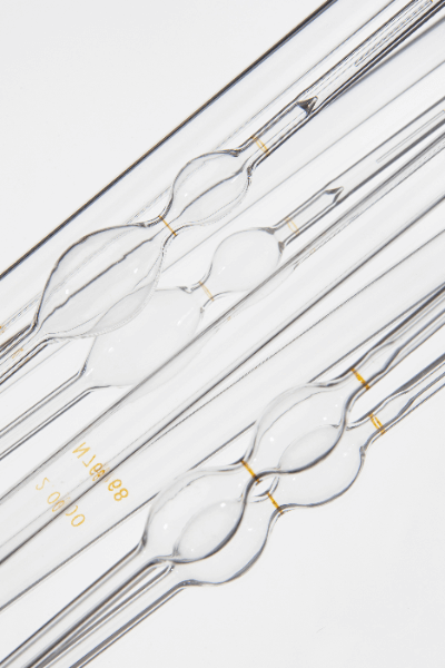
 sterilizer that kills microorganisms (fungi, bacteria, etc.) and viruses.

Ultraviolet rays, which are electromagnetic waves with short wavelengths, damage molecules with their high energy, thereby killing microorganisms and viruses.

In particular, ultraviolet rays with a wavelength of 280 nm or less, known as UV-C, have the highest sterilizing power among ultraviolet rays. Methods combining ultraviolet light and photocatalysts have been developed, and new sterilization methods using ultraviolet (UV) sterilizers are emerging.

Uses of Ultraviolet (UV) Sterilizers

In recent years, demand for sterilization and removal of airborne microorganisms and viruses has been increasing as a countermeasure against infectious diseases. Ultraviolet (UV) sterilizers play an effective role in this regard.

Especially in winter, when viral infections caused by influenza viruses and noroviruses are more prevalent, the use of ultraviolet (UV) sterilizers to sterilize these viruses by installing them indoors is attracting attention.

In addition, sterilization processes are essential for safety reasons in food and pharmaceutical manufacturing. They are widely used in factories to maintain product hygiene.

Thus, ultraviolet (UV) sterilizers are utilized in various places such as homes, factories, and laboratories.

Principle of Ultraviolet (UV) Sterilizers

In general, the shorter the wavelength of an electromagnetic wave, the higher the energy it possesses.

Visible light, which is visible to the human eye, has a wavelength of 400~800 nm, while ultraviolet light has a wavelength of 200~300 nm, which means it has more energy than visible light. Irradiating various materials with ultraviolet rays, which are high-energy electromagnetic waves, can destroy the molecular structures that make up the materials. Microorganisms and viruses are also composed of molecules such as proteins and nucleic acids (DNA and RNA), which are damaged when directly exposed to high-energy electromagnetic waves such as UV light.

DNA has a double helical structure consisting of a series of building blocks called nucleotides, and UV irradiation of DNA damages the nucleotides and breaks the helical structure. Ultraviolet (UV) sterilizers kill microorganisms by damaging their DNA, thereby killing their cells.

This process is not limited to viruses and other organisms, but also to humans and animals. Therefore, it is important to be aware of the risks and characteristics of UV light and to use it correctly.

Other Information on Ultraviolet (UV) Sterilizers

1. Characteristics of Ultraviolet (UV) Sterilizers

Ultraviolet (UV) sterilizers can kill microorganisms and viruses in water and air. Compared to sterilization by chlorine, it can be used to sterilize air and has the advantage of having no odor or irritation. Also, compared to sterilization by ozone, it can be done with simple equipment and does not require toxic gases.

High-temperature, high-pressure sterilization equipment (autoclave) is an effective method for killing microorganisms and viruses, but the treatment time is long and the high temperature and pressure cause denaturation of the material. Ultraviolet (UV) sterilizers, on the other hand, are the sterilization method of choice because they require less time and have minimal impact on the material.

Due to its extremely low environmental impact and high safety characteristics, UV sterilization is expected to be applied in a wide variety of situations.

2. Precautions for Using Ultraviolet (UV) Sterilizers

Since ultraviolet rays exert their sterilizing effect only on directly irradiated areas, sterilization of areas blocked by objects may be inadequate. Therefore, proper irradiation of ultraviolet (UV) sterilizer is important.

In addition, since direct irradiation of ultraviolet rays poses the risk of skin cancer and blindness, great care should be taken to avoid direct irradiation of the human body.

カテゴリー
category_usa

Ultraviolet (UV) Meters

What Is an Ultraviolet (UV) Meter?

Ultraviolet (UV) Meters

Ultraviolet (UV) meters are instruments that measure the intensity of ultraviolet light. Ultraviolet light has a very short wavelength and is invisible to the human eye. Ultraviolet light ranges from 10 nm to 400 nm.

Ultraviolet light is used for sterilization because its short wavelength gives it high energy, making it highly effective for sterilization, and it also interacts with oxygen to produce ozone. On the other hand, DNA has an absorption band at certain wavelengths of ultraviolet light, and when DNA absorbs ultraviolet light, the DNA is damaged, which is harmful to the human body.

It is a very important light source for industrial purposes because of its various other effects. For this reason, it is important to measure UV light, and an ultraviolet (UV) meter is needed to measure its intensity.

Uses of Ultraviolet (UV) Meters

Uses of UV light are wide-ranging. The action of curing resins is done by irradiating them with ultraviolet light to harden them when filling them with resin in the dental office. UV light is also used to cure semiconductor resists. In this process, if the intensity of the UV light decreases due to deterioration of the lamps used for UV irradiation, the resin will not harden properly, so it is necessary to check the intensity periodically with an ultraviolet (UV) meter.

Ultraviolet (UV) meters are also used in laboratories to conduct experiments using ultraviolet light, to evaluate the characteristics of solar cells, to treat vitiligo, and to control light intensity when ultraviolet light is used to sterilize food and other products.

Principle of Ultraviolet (UV) Meters

High-pressure mercury lamps are often used as a source of ultraviolet light. The mercury vapor is excited by glow discharge inside the mercury-filled lamp and emits light, which contains a high percentage of ultraviolet light.

There is another type of lamp called an excimer that emits ultraviolet light by creating an excited dimer. This one is often used as an excimer laser and is characterized by the fact that it produces a single light with a short wavelength, such as ultraviolet light.

Both high-pressure mercury lamps and excimer lamps have one thing in common: they deteriorate with use. As they deteriorate, the intensity of ultraviolet rays decreases, so it is important to periodically check the intensity with an ultraviolet (UV) meter, especially in industries that require strict UV intensity, such as the semiconductor industry.

Ultraviolet (UV) meters use silicon photodiodes, which are excited by ultraviolet light, and the electricity flowing through the silicon photodiode detects and quantifies the UV light.

カテゴリー
category_usa

Precision Machining

What Is Precision Machining?

Precision machining is not defined in any particular way, but it can be defined as machining that is more precise than cutting and drilling with ordinary machine tools.

When machining materials, the term “tolerance” refers to the inevitable errors that occur during the machining process. Precision machining can be defined as machining with a tolerance of a few microns to a few dozen microns.

Precision machining is not only applied to a wide range of metal materials but also ceramics and resins, making it an indispensable technology in today’s industry.

Uses of Precision Machining

Precision machining is used to produce parts for precision instruments.

One of the most demanding industries for precision machining is the aerospace industry, which manufactures rockets and other components.

Rockets, satellites, and space stations have complex mechanisms, and even the slightest deviation in dimensions can affect their overall operation.

Precision machining is also indispensable in the manufacture of robots and medical devices that require precise movements.

Principle of Precision Machining

Precision machining is not a single type of machine tool, but rather a variety of machines used to process materials into various shapes.

In recent years, even traditional machine tools such as lathe turning and milling have become capable of achieving extremely high precision. Other relatively new technologies, such as wire electrical discharge machining using wire electrical discharge machines, which melt materials by discharging wires, can produce very complex shapes with high precision.

Precision machining begins with the design of the part. This design is done using 3D CAD. The designed part shape is loaded into the machine tool and the machine will machine the part according to the dimensions of the part, rather than having a human operator manually machine the part. This is called computer-aided manufacturing, or CAM, and is currently the mainstream manufacturing method.

Because the design is linked to the various machine tools, the result is a precision machined part that is very close to the designed dimensions.

After machining is completed, surface treatment and other finishing processes are required. After machining, burrs and other such defects, which are thin layers of material sticking to the edges of the cut surface, are removed, and polished. If necessary, further fine-tuning is performed to bring the product closer to the designed dimensions.

Types of Precision Machining

Precision machining refers to high-precision removal machining since the precision of forming is lower than that of removal machining.

There are various types of removal processing, including “cutting,” “grinding,” “polishing,” “electrical discharge machining,” and “cutting.”

Among these, cutting, grinding, and electrical discharge machining are those capable of precision machining. Grinding is positioned as a process to produce surface roughness.

1. Cutting

The types of cutting include “milling,” “turning,” and “drilling.”

In cutting, the selection of the cutting tool, coolant, and machining volume must be strictly controlled to achieve high-precision machining. This is due to residual stress and temperature rise during material removal, which leads to deformation after machining.

2. Grinding Process

Grinding is easy to perform high-precision machining because the amount of work is very small and a large amount of coolant is used, resulting in a smaller temperature rise and less residual stress. However, because grinding is performed as if the surface is stroked with a grinding wheel, there are some restrictions on the shape of the workpiece. For example, the corners of a square hole cannot be machined.

3. Electric Discharge Machining

There are three types of EDM: “Die engraving EDM,” which digs into the material in the opposite shape of the electrode; “wire EDM,” which performs contouring; and “small hole EDM,” which creates a small hole by melting and removing the electrode, requiring an EDM machine that is suitable for each processing method.

EDM is a process in which electricity is passed through a thin electrode, causing an electrical discharge between the material and the electrode to remove the material, and the thinner the electrode, the higher the machining accuracy. The thinner the electrode, the slower the processing speed. Today, it is possible to manufacture parts that can be fitted together so precisely that no seams can be seen.

Electrical discharge machining is characterized by its ability to perform more delicate machining than cutting and its ability to process hard materials. Also, since the material is submerged in the machining fluid, heat-induced mutations are less likely to occur, and even materials with complex shapes or thin sheets that are prone to distortion can be machined precisely.

Precision Machining Accuracy

Machining accuracy does not simply depend on the accuracy of the machine, but also on various conditions such as material, machining method, fixing method, temperature, and so on.

For example, when machining two holes on different surfaces, if the first hole is machined, the direction of the material is changed, and the second hole is machined again, the distance between the two holes is the sum of the accuracy of the machine’s movement and the repeatability of the material fixation.

Also, some machining centers can detect a reference (surface, hole, etc.) and machine by the relative distance from the reference, but in such cases, the measurement accuracy of the reference detection is also added.

In this way, the more processes are involved in machining accuracy, the more the error will accumulate. For example, use a machining center equipped with ATC and perform most of the machining in a single chuck.

Furthermore, since the condition of the tool cannot be ignored, various methods are used to improve accuracy, such as measuring the tool’s installation length, outside diameter, runout, etc., and applying compensation.

Currently, high-precision machining is generally limited to an error of a few microns, but sub-micron accuracy is now possible for some products.

カテゴリー
category_usa

Viscometers

What Is a Viscometer?

ViscometersA viscometer is a measuring instrument used to determine the viscosity of a liquid.

Viscometers are used in the chemical industry, for example, to measure the viscosity of adhesives and paints. Viscosity is also very important in the food and beverage industry. Even food products made in the same way may not be viable as products if they have different viscosities, so viscometers are widely used in the food and beverage industries.

Viscometers can be divided into two main types: those that simply measure the time it takes for a liquid to pass from the top to the bottom, and those that use a rotating spindle.

Uses of Viscometers

Viscometers are used in the food, beverage, and chemical industries to measure the viscosity of products.

If the taste is the same, but the viscosity is different, the sensation when pouring into a container or the sensation when actually drinking the product will be different, resulting in a completely different food product. Therefore, viscosity is an important indicator of food products. Viscosity is also an important indicator of the chemical industry. If the viscosity is high, for example, an adhesive applied to a wall will not drip, making it easy to use, but on the other hand, it will be difficult to handle and handle.

Principle of Viscometers

Viscometers are devices used to measure the viscosity of liquids. Viscometers are based on a variety of principles, but the main principles used are as follows:

1. Vibration Damping

The viscosity of a liquid is measured by measuring the damping of vibration by a vibrating body. When a vibrating body vibrates in a liquid, the vibration is damped by the viscous resistance generated in the liquid. By measuring the degree of damping, the viscosity of the liquid is calculated.

2. Pressure Loss

Viscosity of a liquid is measured by measuring the flow velocity and the pressure drop of the fluid as it flows through a pipe. Liquid is poured into a pipe set to flow at a constant flow rate and the pressure drop is measured. If the viscosity of the liquid is high, the pressure drop will be large, and thus viscosity can be measured.

3. Falling Velocity (Time)

Viscosity of a liquid is measured by measuring the speed of a small sphere falling into the liquid and the time taken by the fluid to flow down. Since the speed of a falling sphere and the time it takes for the fluid to flow depend on the viscosity of the liquid, the viscosity of the liquid is calculated by measuring these speeds.

Types of Viscometers

The method of measuring viscosity varies from device to device, with different characteristics and measurement ranges. The main types of viscometers are capillary viscometer, falling-ball viscometer and rotational viscometer.

1. Capillary Viscometer

A capillary viscometer is one of the simplest and most straightforward methods of measuring viscosity. A fluid is poured into a capillary tube at a constant temperature and the time taken for the fluid to pass through the capillary tube is measured. It is very simple, but if the viscosity is too high, the fluid will take a very long time to pass through the container, or will not flow at all due to pressure loss. Depending on the shape, there are the Canon-Fenske, Ueberode, and Ostwald types.

2. Viscosity Cup

Similar to the capillary viscometer, the viscometer cup measures the outflow time of the fluid flowing from the cup. Each cup has a specific viscosity range and can measure almost any viscosity, but the disadvantage is the large measurement variation.

3. Falling-Ball Viscometer

A falling-ball viscometer, such as the Heplerian falling-ball viscometer, fills a container with fluid and measures the time taken for the pebbles to fall between the lines. Viscosity is determined by Stokes’ equation. The viscosity range is wide, but it cannot measure paint or ink, for which the pebbles are not visible.

4. Type B Viscometer

The B-type viscometer is the most commonly used rotational viscometer in industrial applications. It rotates a rotating body called a spindle in a liquid and converts the torque into a viscosity value. It is very easy to use, but there is a possibility of a slight error due to the thickness of the spindle.

5. Tuning-Fork Viscometer

A tuning-fork viscometer is another type of viscometer. The tuning-fork vibrometer resonates an oscillator in a liquid and determines viscosity from the excitation force required to move the oscillator at a constant amplitude. The tuning-fork vibration method is very sensitive and can be used when precise measurement is required.

Tuning-fork vibrometers can also be used to measure viscosity in-line, detecting changes in vibration as viscosity. Inline viscometers can continuously measure viscosity in flowing fluids, so they are used in lines and tanks where constant viscosity measurement is required.