カテゴリー
category_usa

Conductive Paints

What Is a Conductive Paint?

Conductive paints contain conductive materials like metal powder or carbon, mixed into a resin base. These paints are applied to various surfaces, including electrodes, electronic substrates, capacitors, and insulators, forming a conductive film that helps suppress static electricity. They offer stable conductivity and durability without peeling over time.

Conductive paint is beneficial for heat-sensitive materials, as it eliminates the need for high-temperature processes like soldering.

Uses of Conductive Paints

These paints are widely used in the industrial sector for creating conductive circuits on electronic components, such as circuit boards and displays, and for applying on stretch-resistant films. Additionally, they are crucial in preventing static electricity-related malfunctions in electronic devices and are applied to various materials, including construction materials and fibers, for anti-static treatment.

Principles of Conductive Paints

Conductive paints typically contain conductive fillers like carbon or metal powders and surfactants. While carbon and metal fillers are common, tin oxide (SnO2) is used for transparent paints. The paints also include cationic, anionic, and nonionic surfactants, with cationic being the most common. Surfactants’ conductivity varies with humidity and temperature, so they are often mixed with conductive fillers. For optimal conductivity, these fillers are finely and uniformly dispersed using tools like a ball mill.

Types of Conductive Paints

Different types of conductive paints are tailored for specific applications, with characteristics varying based on the surface being painted. For instance, nickel-based paints are durable and heat-resistant up to 80°C. Silver paints offer the highest conductivity, adhering well to glass, polyethylene, and general resins, withstanding temperatures up to 130°C. Silver-copper materials offer high conductivity but may discolor, with a heat resistance of about 80°C. These are also available in spray forms, suitable for coating flexible materials. Pen-type conductive paints are ideal for small-scale applications, such as repairing remote controls and precision equipment.

Conductive Paints for Repairing Remote Controls

Conductive paints are particularly useful for fixing unresponsive buttons in remote controls. By applying the paint to the conductive rubber that contacts the base inside, conductivity is restored. Cleaning the surface with ethanol before painting is essential to remove any dirt and ensure effective conductivity restoration. This application is also beneficial for repairing PCs and other precision devices, where small, pen-type conductive paints can be used for precise application.

カテゴリー
category_usa

Ultrasonic Cleaners

What Is an Ultrasonic Cleaner?

There are two types of cleaning: chemical cleaning using detergents and solvents, and physical cleaning, using vibrations and mechanical energy.

Ultrasonic cleaners are devices that utilize the synergistic effects of both of these.

These devices are available in various sizes.

Small devices include inexpensive household devices used to clean eyeglasses and accessories, etc., those with built-in ultrasonic oscillators such as those used in laboratories to clean instruments and adjust chemicals, and those in which the ultrasonic oscillator is placed in a container of your choice (throw-in type).

Large-scale devices are mainly for industrial use, such as those incorporated into factory manufacturing processes.

The cleaning power varies depending on the ultrasonic waves generated, so it is necessary to select the frequency and detergent according to the application.

The Radio Law may regulate ultrasonic cleaners, so please follow the appropriate procedures according to the output, etc., when installing the device.

(Basically, ultrasonic cleaners with an output of 50 W or more require an application for a permit for high-frequency use equipment.)

Uses of Ultrasonic Cleaners

Ultrasonic cleaners are mainly used for industrial purposes.

Primary applications include degreasing and cleaning metal parts and resins, removing abrasive particles and dust, cleaning precision metal parts, optical disks, and hard disk heads, final cleaning of glass substrates, and cleaning silicon wafers.

Ultrasonic cleaning is performed at low frequencies for metal parts and at high frequencies for silicon wafers.

Ultrasonic cleaners are also used for defoaming, degassing, dispersion, agitation, and crushing.

Principles of Ultrasonic Cleaners

Sound is generated by vibrating objects.

When electrical energy is applied to unique ceramics called piezoelectric ceramics, the ceramics expand and contract.

The vibrations generated at this time are converted into sound.

If the frequency of this sound is set to 20 kHz or higher, ultrasonic waves are generated.

The ultrasonic vibration is applied to the sample to generate bubbles. When the bubbles burst, the microjet water flow generated by the impact (cavitation) is used to clean the sample.

Low-frequency ultrasonic waves are used to degrease and clean metal parts, resins, and precision metal parts.

The shock waves from cavitation can clean even stubborn dirt.

High-frequency ultrasonic waves are used to clean semiconductors and silicon wafers.

Cavitation is generated in different ways depending on the depth of the liquid and the type of liquid.

For ultrasonic cleaning, control of these factors is also essential.

Insufficient control may cause the diaphragm to deteriorate.

Manufacturers for sale include Honda Electronics, Nihon Seiki Seisakusho, SND, and KAIJO.

There are also used products available for purchase or rental.
カテゴリー
category_usa

Crimping Machinery

What Is Crimping Machinery?

Crimping Machinery

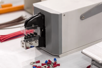
Crimping machinery is a tool used to perform a process called “crimping,” which is used to join metal terminals and wires.

Crimping refers to the process of electrically joining wires and crimp terminals by crushing them with a special caulking die. Crimping machinery is used to crush the wire and crimp terminal by placing a special crimping die on the top and bottom of the wire and crimping the terminal between the wire and terminal.

The crimping part of the crimping machinery looks like a pair of pliers, and the application of force causes plastic deformation on the crimping terminal side, causing the terminal to bite into the wire, thereby binding it.

There are both manual and electric crimping machines, and they are used in different ways depending on the application. The electric type is mainly used for thick wires in particular. The reason for this is that the size of the crimp terminal increases proportionally with the size of the wire, making it difficult for the terminal to undergo plastic deformation during crimping, and therefore greater force is required to crimp the terminal, which cannot be handled by human power in some cases.

Uses of Crimping Machinery

Crimping machinery is used to crimp wires in various places.

Examples include automobiles and home appliances. In order to enable the use of various functions, many wires are wired inside these products, and each wire and crimp terminal is inserted into the connector, which is the joint between the wires, in a pair. By using crimping machinery to crimp these wires and terminals, a highly reliable electrical connection can be achieved.

The specific procedure for the crimping operation is to strip the wire coating to expose the inner core wire, and then set the wire on the crimping terminal with the wire overlapping the terminal. The wires are then clamped from the top and bottom with a special crimping machine, and force is applied to cause plastic deformation of the terminals and bond them together.

Crimping is also used for parts that are sensitive to heat or chemicals. In addition to crimping, soldering can also be used to electrically bond wires, but soldering requires the application of heat, making soldering difficult in some cases. In contrast, crimping does not require heat or chemicals, so it is used for many wires because of its high speed and reliability of electrical connection.

Principle of Crimping Machinery

Crimping machinery is a tool to join wires and crimp terminals by applying a load and crushing them with a special caulking die.

There are both manual and electric crimping machinery, and here we introduce the principle and features of these two types of crimping machinery.

1. Manual Crimping Machinery

The crimpers are shaped like pliers and are hand held by a person. The wire and crimp terminal are set, and the crimp is made by crushing the wire between the terminals.

The advantage is that because the crimping is performed by human hands, the work can be easily performed anywhere, and the crimping can be done mechanically and electrically with a high degree of reliability.

The disadvantage is that the load applied during the operation is limited due to the fact that it is manually powered. Therefore, especially in the case of thick wires, the crimping may not work well because of the force that tries to undo the deformed crimp terminal when load is applied.

2. Electric Crimping Machinery

Crimping is performed in the same way as with manual crimping machinery, but the crushing operation is performed electrically.

The advantage of the electric crimping machine is that it can crimp even thick wires. The thicker the wire, the larger the crimp terminal becomes in proportion to the wire size, so a large amount of force is required to generate plastic deformation in the terminal. However, with electric crimping machinery, the load applied can be easily controlled, so even thick wires can be joined.

Electric crimping machinery is used especially for wires in areas where large currents are flowing, because very thick wires are used due to heat resistance.

The disadvantage is that they cannot be easily installed anywhere. Because they are electrically powered, they require batteries or a power source to operate, making outdoor use difficult. They are also heavy and difficult to miniaturize, and the price of the main unit is high.

カテゴリー
category_usa

Fixed Attenuators

What Is a Fixed Attenuator?

Fixed Attenuators

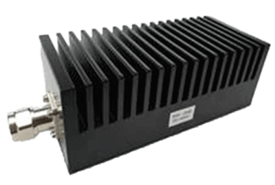
A fixed attenuator is a circuit or device designed to reduce the strength of an incoming signal to a specified level, typically measured in decibels (dB).

The most common type of attenuator features male and female BNC or F-type connectors on both ends, with the attenuator body sandwiched between the connectors. These attenuators are compact and roughly the same size as the connectors in terms of thickness.

Some types of fixed attenuators allow for switching between various attenuation levels.

Fixed attenuators are used not only for electrical signals but also for measurements involving physical quantities, such as light.

Uses of Fixed Attenuators

Fixed attenuators serve several purposes, including adjusting the output signal level in relation to the input signal, achieving impedance matching between the receiving and transmitting sides to obtain the desired output, and preventing unwanted reflections in a circuit. They are also used to minimize the generation of unwanted reflected waves in a circuit.

While fixed attenuators reduce signal strength, boosters, which are circuits or devices that amplify input signals to the desired level, are employed when input signal levels are too low. For instance, boosters are used in areas with weak reception to enhance the performance of TVs and radios by amplifying incoming signals.

Principles of Fixed Attenuators

Fixed attenuators consist of resistors arranged in a T-shape or π-shape configuration.

The level of attenuation can be precisely controlled by adjusting the resistor values and the number of stages in the T- or π-shaped circuit.

Fixed attenuators are predominantly used in audio equipment and various broadcasting equipment, such as TV broadcasting.

In audio equipment, user-defined effects are added to the input audio signal within the internal circuitry before it is transmitted to the loudspeakers. Many of these effects have independent circuit configurations. If a circuit enhances low-frequency characteristics, the signal is passed from the output to the next stage of the circuit.

In such cases, it is crucial to maintain the output signal level within an optimal range. If the output signal level is expected to be too high, a fixed attenuator should be introduced into the circuit.

Excessive signal levels sent to the loudspeaker can result in distorted audio quality. Conversely, if the circuit configuration suggests that the output signal level will be too low, an amplifier circuit (booster) should be incorporated.

When receiving broadcast signals, like TV and radio, there are instances where the input signal level is exceptionally high. For example, signals may be received in close proximity to the broadcast transmitter. In such scenarios, a fixed attenuator should be placed before the antenna input terminal to reduce the incoming signal level to the desired level. Failure to do so may result in unwanted noise contaminating the reproduced video or audio.

カテゴリー
category_usa

Liquid-Solid Separators

What Is a Liquid-Solid Separator?

Liquid-solid separator devices are used to separate and remove solids from liquids. They are primarily employed in the field of sewage treatment.

Sewage treatment involves two stages: the separation of solids from sewage and the treatment of pollutants dissolved in the water. The former is accomplished through the use of liquid-solid separators, which are a more cost-effective solution. The latter is challenging to address with liquid-solid separators, and biological treatments such as activated sludge are generally employed. If pollutants persist in the liquid, the accumulation of excess sludge after biological treatment can increase, leading to a deterioration in treatment efficiency.

Uses of Liquid-Solid Separators

Liquid-solid separators find applications in the pretreatment of sewage and in the dehydration and concentration of sludge. The choice of equipment varies based on the dewatering method employed and whether a coagulant is added.

Equipment that removes solids through screens, among other methods, is utilized for sewage treatment. Examples include screw presses, roller presses, and belt screens. Equipment used for sewage treatment can operate without the addition of flocculants.

For sludge treatment, vacuum dehydrators, pressure dehydrators, belt presses, screw presses, and centrifugal dehydrators are commonly used. These sludge treatment devices primarily rely on the use of flocculants.

Principles of Liquid-Solid Separators

Liquid-solid separators are mainly employed for dewatering through filtration or centrifugal force. Since the moisture content of the cake after treatment differs between these two types of methods, the choice depends on the nature of the sludge being treated.

Typical examples of filtration-type dewatering equipment include pressure dehydrators and belt presses. In a pressure dehydrator, a pressurizing pump forces the sludge into a filter chamber for dewatering. Although there are some drawbacks, such as the need for cake discharging and assembly after each dewatering cycle, the advantage is the ability to apply a significant amount of filtration pressure.

In the case of the belt press, sludge is coagulated using a polymer coagulant and then dewatered using a belt-shaped filter cloth. Liquid sludge is pre-concentrated by gravity and then pressed using rolls because it seeps from between the belts. Pressurized dehydrators have traditionally been the primary choice for filtration systems, but belt presses are gradually gaining popularity.

Centrifugal dehydrators dewater the sludge by utilizing centrifugal force. Centrifugal dehydrators harness the centrifugal force generated by high-speed rotation and can be classified into cylindrical and conical types based on the shape of the rotating body. The cylindrical type is suitable when maintaining the clarity of the liquid is crucial, whereas the conical type is preferred when reducing the moisture content of the cake is the primary objective.

カテゴリー
category_usa

Frequency Converters

What Is a Frequency Converter?

A frequency converter is a device designed to convert an input frequency to an arbitrary output frequency.

Frequency, also referred to as the frequency of oscillation, represents the number of times an electric current or radio wave completes a full cycle per second. Electric currents can be either direct current (DC) or alternating current (AC). Typically, power sources in homes and factories supply AC at a fixed frequency.

However, there are situations where specific machines or equipment require a different frequency than what the power supply provides. In such cases, frequency converters are employed to transform the incoming current to the desired frequency.

Applications of Frequency Converters

Frequency converters find applications when there is a need to modify frequencies. For instance, this is relevant in home appliances and industrial settings.

Regions around the world may have different standard frequencies for their power supply. For example, Eastern Japan uses a 50 Hz frequency, while Western Japan uses 60 Hz. To ensure compatibility, frequency converters are installed to enable the use of electrical devices in regions with different frequency standards.

Furthermore, certain machine tools may require power supplies with lower or higher frequencies than the standard 50 Hz or 60 Hz, necessitating the use of frequency converters.

Principle of Frequency Converters

Frequency converters achieve their function by utilizing both inverters and converters.

An inverter is a device that transforms DC into AC, while a converter is a device that changes AC into DC.

1. Converter Circuit

The converter circuit initially converts the incoming AC into DC. Since AC is a sinusoidal wave with positive and negative values, the converter circuit uses diodes to perform full-wave rectification, ensuring that both positive values are extracted.

Next, the extracted current passes through a capacitor. The capacitor’s role is to smooth the current by repeatedly charging and discharging, resulting in a continuous and stable DC.

2. Inverter Circuit

Subsequently, the current proceeds through an inverter circuit, which generates an AC with the desired frequency. This is achieved through the use of transistors within the inverter circuit, allowing for the adjustment of the ON/OFF switching interval, which, in turn, varies the output frequency.

Pulse Width Modulation (PWM) is a common technique employed in inverter circuits. PWM controls the output by managing the ON/OFF ratio of switches, offering advantages such as reduced power consumption and compactness. In an inverter circuit, the direction of current flow through the load is reversed when the switch is toggled ON/OFF. This technology, known as switching technology, is essential for generating alternating current.

3. PWM (Pulse Width Modulation)

One of the PWM control methods involves triangular wave comparison. In this method, a sine wave of the desired frequency (AC) is compared with a high/low triangle-shaped wave known as a carrier, using an operational amplifier. When the sine wave exceeds the carrier, the switching control signal is set to ON. Conversely, when the sine wave falls below the carrier, it switches to OFF. This comparison is repeated to produce a switching control signal, resulting in a pulse wave output.

AC voltage is supplied by switching DC using semiconductor switching devices like thyristor.

Other Information on frequency converters

1. Thyristor

The thyristor, also utilized in frequency converters, consists of a diode with a gate terminal. The diode permits the flow of electricity in one direction only.

The gate terminal’s role is to control the opening and closing of the electrical circuit. When combined with a diode, it enables control over the direction and output of the current.

2. Thyristor valve

A device capable of withstanding high voltages and possessing the required electrical capacity is known as a valve or rectifier. It is created by connecting several thyristor elements in series or parallel.

While earlier thyristor valves used air-insulated wind-cooling or oil-insulated oil-cooling systems, modern systems often employ air-insulated water-cooled systems, which use large-capacity thyristor elements to efficiently handle high-power applications.

カテゴリー
category_usa

Bench Lathes

What Is a Bench Lathe?

First of all, a lathe is a machine that rotates metal or other material to be processed and slowly applies a metal cutting tool (bite) to its surface to cut it into a cylindrical shape.

Since commercial lathes are large and expensive, Bench lathes are small and can be used as table-top lathes.

Bench lathe consists of a bed, spindle head, tool rest, and tailstock.

The spindle in the spindle head holds the material and rotates it at a constant speed. The tool rest holds the metal blade for cutting.

In addition, the tailstock is installed opposite the spindle head, and by changing the tip, drilling holes can be processed.

Uses of Bench Lathes

Bench lathes are often used to process hard materials, such as metal, because they can cut a rotating material with a tool.

Bench lathes are easily handled by individuals and are available from a variety of manufacturers.

Like ordinary lathes, they excel at machining cylindrical shapes. Bench lathes are very useful when drilling holes or machining screws.

Bench lathes were originally used for manufacturing machinery such as automobiles, aircraft, and construction equipment, but with the advent of bench lathes, machining can now be performed in more familiar settings.

Principles of Bench Lathes

Let’s take a closer look at the characteristics of lathes. Bench lathes can be considered in the same basic way.

Depending on the structure of the lathe, there are vertical lathes and horizontal lathes, and these can be distinguished according to the direction of the spindle.

In the former, the spindle is vertical, while in the latter, it is horizontal.

The vertical lathe has the spindle at the bottom and the tool post at the top, and is suitable for heavy vertical machining.

The advantage is that gravity and centrifugal force are evenly applied to the object, resulting in better machining accuracy.

On the other hand, because it is vertical, it is difficult to machine objects that are too long, and conversely, it takes more time and effort to machine a small object.

The horizontal lathe has a spindle positioned horizontally, which makes machining easier than with a vertical lathe.

It is easy to process long materials, which is difficult with a vertical lathe, and it is also characterized by its superior dust emission during cutting.

One demerit is that it is somewhat more difficult to perform high-precision machining than with a vertical lathe.

How to Use Bench Lathes

Because they are small and not equipped with a CNC control system, they are not suitable for mass production. Therefore, they are suitable for machining one-off, small parts, such as custom-made jigs and prototype tools.

The same basic operations as those for a general-purpose lathe are to mount the workpiece (blade) on the tool rest, align the height of the workpiece by placing a plate between the workpiece and the tool rest so that the center of the workpiece is near the center, and fix the workpiece in the chuck. However, because it is smaller than a general-purpose lathe, if too much is cut at once during roughing, the spindle will stop rotating, so it is necessary to process with a smaller amount.

Bench lathes can be used not only for business, but also for home use.

What a Bench Lathe can do

Although small in size, like a general-purpose lathe, a bench lathe can perform basic cylindrical workpiece external diameter machining, boring to machine the inside shape, drilling with a drill or reamer attached to the centerstock, thread cutting, and plunge cutting to cut materials.

A woodworking bench lathe can be used to make wooden tableware, and metalworking can be used to make die holders and small-diameter shafts. Bench lathes are attractive because they are light, take up little space, and can be powered by a household power source, making it easy to process small parts for a variety of uses.

Bench lathes can be used not only for industry but also for hobbies, such as making plastic model parts and crafts, because they can process not only steel and wood but also plastic, aluminum, and brass materials.

On the other hand, the rigidity of the machine does not allow for the machining of large-diameter workpieces, tool steel, or hardened steel, and the lack of CNC control makes mass production impossible, so it is not suitable for serious parts manufacturing.

カテゴリー
category_usa

Desktop CNC Machines

What Is a Desktop CNC Machine?

Desktop CNC machines are miniaturized table-top versions of the milling machines normally used in factories.

As with ordinary milling machines, a cutting tool (milling machine) attached to a rotating spindle is used to cut materials.

While commercial milling machines are large and expensive, desktop CNC machines make it easy for home users to engage in craftwork.

Desktop CNC machines consist of a spindle, column, and saddle. They are classified into vertical and horizontal types according to the direction of the spindle.

Uses of Desktop CNC Machines

Desktop CNC machines are mainly used for cutting hard metals.

Due to their cutting characteristics, they are suitable for making flat or curved surfaces, grooves, etc., on metal materials.

It can be used at home or in the office, and materials can be easily processed.

On the other hand, there are some materials that are difficult to mill. For materials with corners, it is difficult to make right angles on all sides because of the curvature in milling.

In such cases, the milling machine can either leave the curvature at the corners or widen the corners slightly.

Principles of Desktop CNC Machines

Let us take a closer look at the characteristics of milling machines. The same can be applied to table-top milling machines.

Depending on the construction of the milling machine, there are two types of milling machines: one with an up-and-down table and one with an up-and-down spindle. They are called “knee type” and “bed type,” respectively.

In the knee type, the table is moved up and down, allowing easy machining even if the shape of the workpiece is different.

Depending on the orientation of the spindle, there are vertical and horizontal types, but the vertical type is currently the most common.

This is because the main method is to use a tool similar to a drill, called an end mill, to cut with the side edge.

Another method called face milling, in which the material is cut in a flat shape, is also often used in the vertical form.

On the other hand, in the bed type, the spindle can be moved up and down to enable powerful cutting. As with the knee type, there are vertical and horizontal types.

Since the table does not move, both types have advantages over the knee type in terms of maintaining accuracy and loading weight.

カテゴリー
category_usa

Kinematic Viscometers

What Is a Kinematic Viscometer?

A kinematic viscometer is an essential measuring instrument used to determine the kinematic viscosity of a fluid.

Kinematic viscosity, often referred to as “kinematic viscosity count,” quantifies how resistant a fluid is to flow. It’s important to distinguish kinematic viscosity from “viscosity,” which measures the stickiness or thickness of a fluid. While viscosity assesses how objects move within a fluid, kinematic viscosity assesses the fluid’s inherent resistance to movement. Kinematic viscosity is defined as the viscosity divided by the density of the fluid in the same viscosity state, and a kinematic viscometer is the instrument used to measure it.

Both viscosity and kinematic viscosity are measured using six types of viscometers.

Applications of Kinematic Viscometer

Kinematic viscometers find extensive use in the inspection and development of fluid products because kinematic viscosity is a critical parameter that affects material handling and properties. For example, in the food industry, variations in viscosity impact the drinkability of beverages, and creamy food products are influenced by their ease of handling and melt-in-your-mouth characteristics.

Additionally, kinematic viscometers play a crucial role in quality control, inspection, and product development across various industries, including petrochemicals, pharmaceuticals, paints, and industrial oils.

Principle of Kinematic Viscometer

Kinematic viscometers measure kinematic viscosity using various methods. These methods include the capillary viscometer, falling-ball viscometer, concentric double-cylinder rotational viscometer, single-cylinder rotational viscometer, flat-plate rotational viscometer, and oscillating viscometer.

All these methods evaluate kinematic viscosity by deforming a fluid, such as rotating it, passing it through a narrow tube, immersing a ball, or vibrating it, and then assessing the changes induced by these actions.

Types of Kinematic Viscometers

There are four typical types of kinematic viscometers, except for the capillary viscometer, which directly measures viscosity. To obtain kinematic viscosity, one must divide viscosity by the density of the fluid.

1. Capillary Viscometer

The capillary viscometer calculates kinematic viscosity by passing a fluid sample through a small tube and measuring the time it takes to flow through. Unlike other methods, the capillary viscometer directly determines kinematic viscosity. It is a cost-effective and long-established technique.

2. Falling-Ball Viscometer

Falling-ball viscometers determine viscosity by dropping a ball into a fluid and measuring the time it takes for the ball to descend. This method is suitable for a wide range of viscosities in Newtonian fluids, which maintain constant viscosity regardless of shear rate.

3. Rotational Viscometer

Rotational viscometers gauge viscosity by measuring the torque exerted on a cylindrical surface when a cylindrical rotor rotates within a fluid sample at a consistent speed. There are several types of rotational viscometers, including the coaxial double-cylinder type, single-cylinder type, and cone-plate type. The cone-plate type is particularly useful for investigating the fluid properties of non-Newtonian fluids by varying the rotation speed.

4. Vibro Viscometer

Vibro viscometers evaluate the viscous resistance of a vibrating component immersed in a sample subjected to specific vibration frequencies. An advantage of vibro viscometers is their ability to measure viscosity even when the fluid is in motion.

Additional Information on Kinematic Viscometer

1. Kinematic Viscosity Units

The SI unit for kinematic viscosity is m²/s. In the past, the unit St (Stokes) = cm²/s was used, with 1 m²/s equating to 1 cSt (centistokes). Viscosity is measured in Pa-s in SI units and P (Poise) or cP (centipoise) in the old units.

2. Difference from Viscosity

It’s crucial to recognize that kinematic viscosity and viscosity exhibit a significant difference in their relationship with density. When comparing kinematic viscosity and viscosity of different fluids, their relationship changes significantly. For example, comparing water and dry air, dry air has a kinematic viscosity about 15 times that of water, while its viscosity is only approximately 1/55th that of water. These differences are largely influenced by the substantial difference in density between water and dry air. In the case of viscous fluids like gear oil, both kinematic viscosity and viscosity are significantly higher than those of water.

カテゴリー
category_usa

Spectroscopic Analyzer

What Is a Spectroscopic Analyzer?

Spectrometers

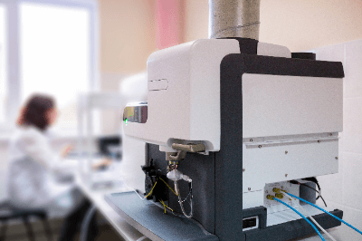
A spectroscopic analyzer is a versatile analytical instrument used to examine the spectrum of light emitted or absorbed by substances. These devices typically consist of a light source, a spectroscopic section, a sample section, and a detector.

Spectroscopic analyzers are categorized based on their light source and operational mechanism. Notable types include ultraviolet-visible spectrophotometers (UV-Vis), infrared spectrophotometers (IR), inductively coupled plasma atomic emission spectrometers (ICP-AES), atomic absorption spectrometers (AAS), fluorescent X-ray spectrometers (XRF), and X-ray photoelectron spectrometers (XPS). Each instrument serves specific analytical purposes due to its distinct capabilities.

These analyzers are indispensable tools for both qualitative and quantitative analysis of samples in various fields, including research, quality control, and chemical analysis.

Types of Spectroscopic Analyzers

Spectroscopic analyzers can detect the light emitted or absorbed by substances, enabling a wide range of analyses. Here are six representative types of spectroscopic analyzers:

1. Ultraviolet-Visible Spectrophotometer (UV-Vis)

This instrument utilizes ultraviolet or visible light sources to examine light transmitted through or reflected from a material. It facilitates qualitative and quantitative analysis of sample components.

2. Infrared Spectrophotometer (IR)

IR spectrophotometers employ infrared light sources to study light transmitted through or reflected from materials. They are used to estimate molecular structures and perform quantitative analysis of sample components.

3. Inductively Coupled Plasma Atomic Emission Spectrometer (ICP-AES)

This device detects luminescence generated when a sample is introduced into an inductively coupled plasma. It offers exceptional sensitivity and is ideal for qualitative and quantitative analysis of trace elements.

4. Atomic Absorption Spectrometer (AAS)

AAS instruments perform qualitative and quantitative analysis of trace elements by measuring the absorption of specific wavelengths of light by atoms.

5. X-Ray Fluorescence Analyzer (XRF)

XRF analyzers conduct elemental analysis of materials using X-rays as the light source. They identify qualitative and quantitative characteristics by observing the fluorescent X-rays specific to each element.

6. X-Ray Photoelectron Spectrometer (XPS)

XPS devices employ soft X-rays as the light source to gather information about the atoms and molecules on the surface of a solid material.

Spectroscopic Analysis

Spectroscopic analysis involves the examination of a substance’s properties by shining light on it and observing its response to the light. The fundamental principle behind this analysis is that materials interact with light in specific ways, allowing us to gather information about them.

For instance, when light illuminates a substance, it can be absorbed, reflected, or emitted at specific wavelengths. Spectrometers are designed to capture and analyze these interactions. By studying the resulting data, various types of information can be extracted, including qualitative and quantitative analysis of samples, molecular structure evaluation, and material property assessment.

The key examples include:

  • The evaluation of the electronic states of molecules using ultraviolet and visible wavelengths.
  • The determination of atomic and molecular arrangements on the surface of solids using X-ray spectra.
  • The analysis of vibrational states between atoms in organic compounds through infrared spectra.

Spectrum in Spectroscopic Analysis

In spectroscopic analysis, the spectrum is a crucial element that provides material information. It is obtained by recording the light intensity at various wavelengths using a spectrometer. The resulting spectrum consists of peaks and troughs, each with a specific meaning depending on the type of spectrometer used.

1. UV-Visible Spectrophotometer

The spectrum often appears as a mountain-shaped curve, with peaks indicating the wavelengths at which electrons enter excited states.

2. Infrared Spectrophotometer

The infrared spectrum can exhibit both broad peaks and sharp lines. The presence of specific peaks reveals the vibrations between atoms in organic compounds.

3. Inductively Coupled Plasma Emission Spectrometer

This instrument detects luminescence emitted when a sample is exposed to inductively coupled plasma. The emitted energy, converted to wavelengths, appears as peaks in the spectrum.

4. Atomic Absorption Spectrometer

Atomic absorption spectrometers identify specific wavelengths of light absorbed by atoms in primarily inorganic substances. These absorbed wavelengths are evident as peaks in the spectrum.

5. X-Ray Fluorescence Analyzer

Similar to luminescence, XRF analyzers record the wavelengths of fluorescent X-rays emitted when electrons return to their ground state following X-ray irradiation, representing peaks in the spectrum.

6. X-Ray Photoelectron Spectrometer

XPS instruments utilize soft X-rays to ionize atoms or molecules on a solid surface, and the emitted electrons’ energy is detected as peaks in the spectrum.