カテゴリー
category_usa

Differential pressure flowmeters

What Is a Differential Pressure Flowmeter?

A differential pressure flowmeter is a flowmeter that measures fluid flow rate by detecting the pressure difference created as the fluid passes through a conduit. This pressure difference, typically generated across a constraining structure like an orifice plate, is used to calculate the flow rate. Differential pressure flowmeters offer a cost-effective solution compared to other flowmeter types and are suitable for high-temperature and high-pressure environments. However, they can have a limited measuring range and may incur high-pressure loss.

Uses of Differential Pressure Flowmeters

Differential pressure flowmeters are versatile tools employed in various fields:

  • Environmental Measurement: For monitoring industrial furnace exhaust gas flow rates.
  • Power Plants: In hydroelectric plants for measuring water flow rate, and in thermal power plants for monitoring steam in boiler and turbine systems.
  • Leisure Facilities: Such as hot spring resorts, to control steam flow rate for heating efficiency.

Principle of Differential Pressure Flowmeters

The operational principle is based on Bernoulli’s theorem. A constraining structure, like an orifice, is installed in the pipeline, causing a velocity increase and pressure decrease in the fluid. Pressure sensors measure the differential pressure upstream and downstream of the structure. This differential pressure, proportional to the square root of the flow rate, allows for flow rate estimation.

Stable flow before the orifice is essential for accurate measurement, requiring a straight pipe length of 5 to 10 times the pipe diameter before the orifice.

Differential Pressure Flowmeter Types

Differential pressure flowmeters come in various forms:

  • Orifice Plate Flowmeter: Uses an orifice plate with circular or oval holes to measure fluid flow rate, commonly used for steam and exhaust gas measurement.
  • Venturi Meter: Features a conical constricted section, offering high accuracy and suitability for a wide range of flow rates.
  • Pitot Tube Flowmeter: Utilizes a conical probe to measure pressure differences caused by fluid velocity changes, especially effective for gas flow rate measurement.
カテゴリー
category_usa

Hydraulic Data Loggers

What Is a Hydraulic Data Logger?

A humidity logger is a device that records humidity at user-specified regular intervals and analyzes the measured data.

The relative humidity unit (relative humidity) is expressed as %RH.

Relative humidity is the moisture content of air at a given temperature compared to the maximum moisture content of air (saturated water vapor).

Relative humidity (%RH) = water vapor content/saturation water vapor content x 100.

Temperature and humidity are usually measured as a set due to the close relationship between temperature and humidity.

The lower the temperature, the less water vapor can be contained in the air. Likewise, the higher the temperature, the more water vapor can be contained.

Uses of Hydraulic Data Loggers

Humidity is an important item in quality control.

Humidity loggers are used for humidity control, which is one of the requirements of the ISO 9001 quality management system.

They are used for temperature and humidity control in museums to prevent mold formation due to high temperature and humidity and damage to works of art due to dryness.

Suitable for temperature and humidity control in warehouses, logistics, hospital environments, civil engineering and construction, and vinyl greenhouses.

There is a wide range of equipment types, including separate sensor types, sensor-integrated types, analog types that constantly record on paper, and multi-loggers for multi-point measurement.

Principle of Hydraulic Data Loggers

Humidity loggers are classified into two types: electrical resistance and capacitance.

The electrical resistance and capacitance types use a moisture-sensitive material that absorbs and dehumidifies moisture and is sandwiched between electrodes.

The capacitance type is the mainstream, can measure humidity even at 20% or less, and has the advantage of a fast response time.

The electrical resistance type is resistant to noise, and the sensor part can be smaller.

Hydraulic data loggers have made it possible to take long-term measurements at user-specified intervals and, depending on the device, to take simultaneous measurements at multiple points or over a wide area simultaneously via wireless communication.

Simultaneous measurement of recorded humidity and temperature, and even impact degree depending on the device, is now possible. Anyone can easily measure and analyze the data on a PC application.

Constant wireless monitoring is especially suitable for preserving artworks and optimizing the environment.

High temperature and humidity can cause damage and deterioration of artwork, so environmental control is essential. The previous analog Hydraulic data logger has been replaced by a wireless Hydraulic data logger, which eliminates the time and effort of opening the display case to collect data. Most importantly, it eliminates environmental changes inside the case.
カテゴリー
category_usa

Mass Flowmeters

What Is a Mass Flowmeter?

Mass Flowmeters

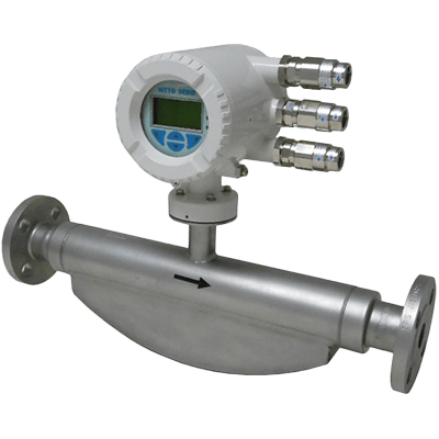
A mass flowmeter is a device designed to measure the mass flow rate of liquids or gases in a fluid stream. Unlike volume flowmeters that measure the volumetric flow, mass flowmeters directly quantify the mass of the fluid passing through them over time. Suitable for both liquid and gaseous fluids, these meters are key in various applications but tend to be more costly than volumetric flowmeters and may require specialized knowledge for installation and operation.

Uses of Mass Flowmeters

Mass flowmeters are employed across different industrial sectors:

  • Oil and Gas Industry: For mixing liquids and gases in refining and gas processing, where varying gas compositions and densities are common.
  • Chemical Plants: In chemical manufacturing, for accurate feeding of raw materials and reactants, and measuring product output.
  • Power Plants: To measure fuel supply and exhaust gases, aiding in efficient power generation and ensuring compliance with environmental standards.

Principle of Mass Flowmeters

Mass flowmeters operate based on principles that leverage physical changes or effects related to fluid mass. They measure mass flow directly, utilizing various physical properties of the fluid. For example, in Coriolis effect-based meters, the fluid mass affects the vibration’s phase difference and displacement. In thermal conduction meters, the mass flow rate is related to the fluid’s thermal conductivity.

Types of Mass Flowmeters

The most commonly used mass flowmeters include Coriolis and thermal types:

1. Coriolis Flowmeter

Coriolis flowmeters measure the mass flow rate by utilizing the Coriolis effect. They feature oscillating tubes through which the fluid flows. The Coriolis force generated affects the tubes’ vibration, and the resulting phase difference and displacement allow for accurate mass flow rate calculation. These meters are highly accurate and versatile, suitable for various fluids, but can be sensitive to external vibrations and challenging to clean.

2. Thermal Flowmeter

Thermal flowmeters use heat transfer principles to measure the mass flow rate, particularly effective with gases. They calculate flow by detecting temperature differences, allowing estimation of mass flow rate based on changes in thermal energy and conduction velocity. These meters are notable for their wide temperature measurement range and low-pressure drop, but they can be affected by contamination, making them less suitable for gases containing oil mist.

カテゴリー
category_usa

Crystallizers

What Is a Crystallizer?

Crystallization is the process of forming solid crystals from a liquid or gas. It is a long-used technique, notably in salt production and the pharmaceutical industry.

The solubility of a solute in a solvent depends on temperature. At saturation, the solute is maximally soluble. Cooling, evaporation, solvent changes, and reactions can decrease solubility, causing some solutes to precipitate as crystals.

Uses of Crystallizers

Crystallizers produce different crystal shapes, with two common types:

  • Crystal Oslo Type: Separates solvent evaporation and crystal growth, using external heat in the evaporation part to precipitate crystals. Its advantage is less crystal fracturing in the growth section due to no circulation by the pump. However, it requires larger equipment due to the need for lower solution concentration. Example: Production of Sodium cyanide used in plating.
  • Inverted Cone Type: Utilizes an inverted cone to separate solvents, exploiting the slower sedimentation rate of larger crystals. This method produces crystals with varied grain sizes. Example: Production of Alum used as a food additive.

Principles of Crystallizers

Crystallization involves the formation and growth of crystal nuclei:

  • Generation of Crystal Nuclei: Under varying pressure and temperature, the solid phase may be more energetically stable than liquid or gas phases. This stability leads to the generation of nano-sized crystal nuclei. Primary nucleation occurs spontaneously from the solution, while secondary nucleation happens when a nucleus detaches from a larger crystal due to an applied force. Primary nucleation is common in laboratory settings, whereas secondary nucleation is prevalent in industrial processes.
  • Crystal Growth: Occurs when atoms and molecules attach to a crystal nucleus’s surface. The crystal surface has steps where atoms and molecules incorporate into kinks, leading to crystal layer thickening and growth. This process is complex and not yet fully understood.
カテゴリー
category_usa

Vacuum Switches

What Is a Vacuum Switch?

A vacuum switch is a device that activates or deactivates an electrical circuit by detecting pressure levels below atmospheric pressure. It operates based on vacuum pressure changes, controlling fluid flow or activating safety mechanisms when specific pressure thresholds are reached. Its unique feature of preventing arcing due to the absence of air makes it ideal for high-voltage electric power applications, where the switch mechanism operates within a vacuum to enhance safety and reliability.

Uses of Vacuum Switches

Vacuum switches have a broad range of applications, including:

1. For Automation Control

They are integral to the safety, protection, and control circuits of automated vacuum equipment. Uses span semiconductor manufacturing, chemical analysis, vacuum deposition, and pressure control systems, benefiting from the compatibility of silicon and stainless steel with various fluids.

2. For Electric Power

High-voltage circuit breakers utilize vacuum switches for reliable power transmission in buildings, factories, and railways. They ensure circuit interruption during malfunctions, with some designed as vacuum electromagnetic contactors for large motor control, primarily in 6kV and 3kV high-voltage circuits.

Principle of Vacuum Switches

Vacuum switches operate by sensing pressure changes and actuating a switch to open or close an electrical circuit. They consist of a sensor and a switch mechanism, which may be electric, pneumatic, mechanical, or electronic. The sensor detects vacuum pressure levels and triggers the switch based on preset limits, ensuring safe operation in various environments. For electric power applications, they interrupt current flow in case of system malfunctions, utilizing a vacuum valve construction to diffuse and quench arcs efficiently.

Features of Vacuum Switches

Key features include:

1. Wide Setting Range

They offer a broad vacuum pressure setting range, accommodating various operational needs.

2. Long Life

Designed for durability, vacuum switches boast a long lifecycle with minimal setting errors, often exceeding 1 million cycles.

3. Compatibility With Various Media

Constructed mainly from stainless steel, their welded seals are compatible with a wide array of gases.

4. Single-Pole, Two-Headed Contact

Many models feature a single-pole, dual-headed contact for precise ON/OFF control at set pressure limits.

Other Information on Vacuum Switches

Vacuum switches are also crucial in managing shock currents in electric power systems and high-temperature plasma experiments, effectively preventing overvoltages and ensuring circuit safety during large current accidents.

カテゴリー
category_usa

Vacuum-Forming Machinery

What Is Vacuum-Forming Machinery?

Vacuum-forming machinery is a type of equipment that heats a plastic sheet and then molds it over a form using a vacuum to ensure the material precisely adheres to the mold. This process eliminates excess air, resulting in the desired shape. After forming, the product is cooled and extracted from the mold. This technology is especially effective for producing thin-walled and large items, offering a cost-effective alternative to injection molding for both small and large production runs.

Uses of Vacuum-Forming Machinery

This machinery is versatile, supporting a range of applications:

1. Molding Plastic Products

Commonly used for creating plastic bottles, food containers, toys, and cosmetic containers.

2. Production of Plastic Sheets and Films

Shapes plastic into sheets or films, suitable for producing sheet materials and laminated films.

3. Packaging Materials for Medical and Pharmaceutical Products

Crafts packaging to protect and seal medical devices and pharmaceuticals, and is also useful for producing sanitary products.

4. Food Preservation

Creates containers and bags for food storage and cooking purposes.

5. Automotive, Home Appliances, and Furniture Manufacturing

Manufactures interior parts for vehicles, appliance housings, and furniture components.

6. Other Applications

Produces filters, pumps, electronic component cases, construction panels, and stationery.

Features of Vacuum-Forming Machinery

Advantages

Offers high precision through specialized molds and heating, with the flexibility to produce various products by changing the mold. It can be integrated into automated lines for efficient production, forming multiple items simultaneously using cost-effective materials.

Disadvantages

The heating, vacuuming, and cooling process may be time-consuming. Initial costs can be higher compared to injection molding, with the potential for lower accuracy if parameters like melting point and vacuum degree are not precisely controlled.

How to Use Vacuum-Forming Machinery

The operation involves heating, molding, and cooling thermoplastic resin:

1. Heating

Thermoplastic resin is heated to soften, using electric or infrared heating methods.

2. Molding

The softened resin is sucked into a special mold using a vacuum, conforming to the mold’s shape.

3. Cooling

Post-molding, the resin is cooled to solidify and maintain its shape, using water or air cooling methods.

Other Information on Vacuum-Forming Machinery

About Vacuum-Packed Bags

Vacuum forming is also used to produce vacuum-packed bags for food, metal, electronics, pharmaceuticals, and cosmetics. These bags, made from materials like polyethylene and nylon, offer protection against oxidation, moisture, and bacteria, extending the shelf life of their contents.

カテゴリー
category_usa

Vacuum equipment

What Is Vacuum Equipment?

Vacuum equipment

Vacuum equipment is equipment that creates a vacuum using a certain power source.

There are three main types of vacuum equipment: ejectors, vacuum pumps, and vacuum blowers. Each is used for different purposes. The main applications of a vacuum include adsorption by suction pads and degassing by reducing the pressure in the system.

Among vacuum equipment, ejectors are very useful because they can be used in areas where hazardous materials are used by using air as the driving force. Vacuum pumps and blowers, on the other hand, are electrically driven and can efficiently create a vacuum.

Uses of Vacuum Equipment

One application of a vacuum is suction with suction pads. This is used to lift a workpiece by adsorbing it when it is transported by a robot or other equipment.

It is also used for degassing by reducing the pressure in a system. For easily oxidizable materials, it prevents oxidation by removing air (oxygen). They can also be used to separate or concentrate liquids by evaporating unwanted water from mixtures or chemicals.

Among vacuum equipment, ejectors use air and are used to generate vacuum inexpensively due to their small size and simplicity. Vacuum pumps are used to create a high vacuum, while vacuum blowers are used to vacuum vented workpieces.

Principle of Vacuum Equipment

Ejectors use the Venturi effect to create a vacuum. The inside of the ejector has a partially constricted structure that allows air, the driving fluid, to pass through at high speed. The area where the air passes through at high speed becomes partially vacuumed. Because of this principle, the driving source is a fluid, and there is a wide variety. Various fluids, such as steam, air, water, etc., can be used.

The vacuum pump rotates the vanes as the motor rotates, and the gas inside the casing is discharged while being sealed. Since the gas is continuously discharged and the motor can be used as the power source, high vacuum and pumping speeds can be achieved. They are also used as pressure reducing equipment to lower the boiling point.

Vacuum blowers use a motor to rotate the built-in blades. As the blower blades rotate, gas is drawn in. By drawing in gas, the gas is compressed to create a vacuum. The feature of the vacuum blower is its large suction volume. However, due to its principle, it can be used more efficiently if the workpiece to be adsorbed has air permeability.

Structure of Vacuum Equipment

Vacuum equipment has different functions depending on the equipment, but the common unit consists of a vacuum pump (ejector, vacuum blower), vacuum chamber, vacuum valve, and vacuum gauge.

1. Vacuum Pump

A vacuum pump is a machine that releases the air in a vacuum chamber to the outside and maintains a low pressure, or vacuum, below atmospheric pressure. The type of vacuum pump used depends on the degree of vacuum required and the composition of the gas to be evacuated. The most common type of vacuum pump is the rotary pump, which is superior in terms of displacement volume, pressure limits, and cost.

2. Vacuum Chamber

A vacuum chamber is a container for creating a vacuum. The vacuum chamber uses a vacuum pump to expel air, which causes the pressure inside the container to drop. When the pressure drops, the vacuum chamber is subjected to pressure from the outside because the outside air pressure is greater than the air pressure inside the vacuum chamber. Therefore, if the vacuum chamber itself cannot withstand the pressure generated, it will not be able to maintain its shape, so care must be taken in selecting the strength of the vacuum chamber.

3. Vacuum Valve

A vacuum valve is a unit that shuts off the different pressures between the vacuum chamber and the vacuum pump. There are different types of vacuum valves, such as the gate bubble, the L-shaped valve, and straight bubble, and the vacuum valve to be used must be selected according to the pressure.

4. Vacuum Gauge

A vacuum gauge is a device that measures the pressure inside a vacuum chamber. Different types of vacuum gauges can measure different amounts of pressure, so it is necessary to use a vacuum gauge that is appropriate for the pressure of the vacuum equipment to be used.

カテゴリー
category_usa

Precision Levels

What Is a Precision Level?

Precision Levels

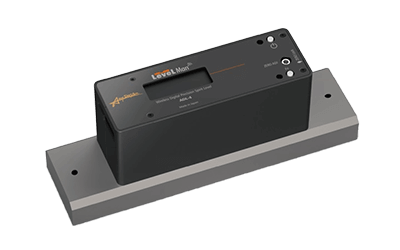
Precision level is used to check the level in the manufacturing process of precision instruments that require a high-level standard. The accuracy of precision levels is strictly defined by the JIS standard. Precision levels that measure the position of bubbles with a sensor to obtain the degree of inclination as a digital signal are also available.

Uses of Precision Levels

Precision levels are used at manufacturing sites where high precision is required, such as in producing precision instruments, semiconductors, and displays. They are used before operating or installing machine tools and manufacturing equipment. They may also be mounted on equipment that requires a high degree of leveling for each operation. When selecting a precision level, it is necessary to consider measurement accuracy, resistance to vibration, whether it is a digital or analog type, suitability for the environment in which it will be used, ease of measurement, size, and other factors.

Principles of Precision Levels

This section describes the measurement principle of a precision level. Precision levels consist of a container, which is precisely calibrated and guaranteed to be level, and a precision enclosure to which the container is attached. The container is slightly curved and contains a defined amount of liquid and gas. In the case of the digital type, an image sensor is built into the area where the bubbles are observed.

When measuring visually, the inclination of the area where the precision level is located is measured by visually checking where the bubbles are located on the scale on the container. In the case of the digital type, by processing the image acquired from the sensor, the degree of inclination is calculated by the built-in control board and shown on the display. It can also function as a sensor to maintain the level by transmitting the degree of inclination as an electrical signal to other connectable devices, performing feedback control, etc. Due to its mechanism, it may not function correctly in environments with a lot of vibration or high temperatures.

Types of Precision Levels

The structure and accuracy of precision levels are determined by the Japanese Industrial Standards (JIS).

Precision levels are classified into three types according to their sensitivity. JIS defines the sensitivity of a level as one type (0.02 mm/m, approx. 4 seconds), two types (0.05 mm/m, approx. 10 seconds), and three types (0.1 mm/m, approx. 20 seconds). Sensitivity refers to the inclination angle required to move a bubble one scale interval, and the sensitivity indication is based on the height relative to 1 meter of the base.

For example, in the case of Type 1, a height of 0.02mm per meter of the base is detected on a single scale, and if a bubble moves one scale using a 300mm size level (Type 1: sensitivity 0.02mm/m), there is a difference in height of 6μm from one end of the level to the other.

Sensitivity is also expressed in terms of tilt angle (seconds). An angle of 1 second is 4.85 µm per meter.

Class 1 0.02mm/m = Angle 4 seconds = 0.00111°.

Class 2 0.05mm/m = Angle 10 seconds = 0.00277°.

Class 3 0.1mm/m = Angular degree 20 seconds = 0.0055°.

Precision Level Grades

JIS classifies precision levels into Class A and B according to their performance (accuracy). The intersection of each performance is as follows. Accuracy is the overall goodness, including accuracy and precision (small degree of variation) of the value or measurement result expressed by the measuring instrument, and is the measurement variation. When a measurement is made, it takes the form of a measured value ± precision, with the actual value of the measurement objective included in the ± accuracy.

According to JIS, the accuracy is as follows.

  • Full range accuracy (Class 1): Class A ±0.5 graduation, Class B ±0.7 graduation
  • Accuracy over the entire range (Class 2 and Class 3): Class A ±0.3 graduation, Class B ±0.5 graduation
  • Adjacent accuracy (Class 1, 2, and 3): Class A, 0.2 graduation. Class B, 0.5 graduation
カテゴリー
category_usa

ESD Simulators

What Is an ESD Simulator?

ESD simulators evaluate the discharge phenomenon commonly referred to as “static electricity,” or the electrical energy generated when charged particles or objects are discharged into electronic equipment. Static electricity testing is one of the most essential items in the EMC testing of IEC (International Electrotechnical Commission) standards for evaluating noise immunity, called ESD (electrostatic discharge) testing. The actual output voltage of the testing machine varies depending on the device, and we select a testing machine suitable for testing per various standards for each product.

Uses of ESD Simulators

In Japan, there are no specific standards for electrostatic discharge testing. However, the IEC international standard includes an “Immunity Test Method for Electrostatic Discharge,” and the European EMC standard EN55014-2 and EN61000-4-2 include electrostatic discharge testing as a test condition, making this test an essential item as an international standard.

The international standard for electrostatic testing classifies the degree to which equipment can withstand static electricity into multiple levels. In the case of contact discharge electrostatic testing, the first level is 2kV, the next is 4kV, the next is 6kV, and the next is 8kV. ESD simulators are used in these tests.

Principles of ESD Simulators

ESD simulators use a contact-type discharge method, which is different from the discharge of electricity charged on the human body in the atmosphere because it is a stable discharge.

In contact-type equipment, a high-voltage relay inside the ESD simulator’s gun is applied via a discharge resistor to a discharge electrode previously in contact with the ESD simulator using an electric charge from an energy-storing capacitor. Compared to the in-air discharge method, which discharges like fireworks in the air, this contact-type discharge is via a mechanical contact point using a high-voltage relay enclosed in inert gas at high pressure, enabling highly accurate discharges.

Currently, mainstream ESD simulators use the contact discharge method. The IEC standard specifies the current waveform to be applied at the time of discharge in contact-type discharges, which are highly reliable. The current waveform applied during discharge can be measured as a voltage drop (current) across a resistor using an oscilloscope or similar device, allowing measurement in compliance with the regulations by checking the waveform before testing.

カテゴリー
category_usa

Insulated Terminals

What Is an Insulated Terminal?

Insulated Terminals

An insulated terminal is a component featuring an insulation coating at the root of the bare crimp terminal. These terminals are installed at the ends of wires to connect them to electronic devices and circuits, with the insulation coating providing electrical insulation and reducing risks like short circuits, electrical leakage, and electric shock.

The insulation sheath also protects wire ends from external damage, ensuring durability against physical shocks and vibrations. However, proper installation tools and techniques are essential to maintain connection reliability and safety.

Uses of Insulated Terminals

Insulated terminals are widely used in various industries, specifically for electrical wiring connections in:

  • Buildings: In wiring connections and branching points, such as for wall outlets and switches.
  • Home Appliances: Connecting wires in devices like air conditioners.
  • Automobiles: In automotive harnesses for wiring electrical systems in vehicles.
  • Industrial Equipment: Electrical wiring of control systems and motors in industrial machinery.

Principle of Insulated Terminals

Insulated terminals consist of an insulation coating, terminal body, and wire connection part:

  • Insulation Coating: Protects the wire with materials like polyvinyl chloride or nylon, chosen for heat resistance and insulation performance.
  • Terminal Body: Made of conductive metals like oxygen-free copper for signal and power transmission.
  • Wire Connection Part: Securely connects the wire to the terminal through crimping, ensuring direct contact between conductors.

Types of Insulated Terminals

Common types of insulated terminals include:

  • Ring Terminals: Widely used terminals with a circular shape, suitable for mounting on screws.
  • Bar Terminals: Straight-shaped terminals, prevalent in Europe, used in wiring junctions and electrical panels.
  • Y-Type Terminals: Y-shaped terminals for easy attachment to bolts or screws, allowing for quick connection and disconnection without complete screw removal.

While Y-type terminals offer installation convenience, there is a risk of loosening. Thus, many manufacturers recommend ring terminals for more secure connections.