カテゴリー
category_usa

RF Filter

What Is an RF Filter?

A filter is an element or circuit that discriminates frequencies, allowing only signals in the required frequency band to pass through and blocking other signals.

An RF filter is a filter for broadcasting wireless communication signals using radio frequency (RF).

In the case of digital terrestrial broadcasting, signals in the 80 to 800 MHz frequency band are used. For cell phones such as smartphones, signals in the 800-3500 MHz frequency band are used. Therefore, an RF filter is used to block signals outside of these frequency bands when they are mixed in.

Uses of RF Filters

The frequencies used for broadcasting and communications are regarded as a finite national asset, and the frequency bands used for each service are determined to use them effectively.

It is necessary to take measures to prevent interference between the two services from adversely affecting each other’s services. RF filters are effective for this purpose.

For example, RF filters are used to receive digital terrestrial broadcasts, allowing only the 80 to 800 MHz broadcast signals to pass through and blocking signals outside this range.

RF filters are available in a compact size and are as thick as an antenna cable, and are used by connecting them vertically to the antenna cable.

Principles of RF Filters

As mentioned above, RF filters are used for TV reception, cellular phones, and other industrial equipment.

Television broadcasting frequencies range from 80 to 800 MHz, while cellular phone communication frequencies are on the upper end of that range, from 800 to 3500 MHz. The frequency bands used by the two are separated, so problems should not occur.

However, if the frequencies handled by the internal circuits of the cellular phone step into the frequency band of the TV due to some trouble or equipment design problem, for example, there is a possibility that the image and sound on the TV side may be affected as noise.

In such a case, RF filters that allow only the signals in the frequency band of the TV set to pass through can be inserted in the TV set to prevent the problem.

Although this level of support may not be necessary when watching TV in the home, it is a possible safety measure to avoid problems due to noise contamination during the viewing process when using TVs for business purposes.

Industrial equipment requires more precise operation than consumer equipment, and it is necessary to eliminate as much as possible the reception of unnecessary radio waves that could cause malfunctions.

A special example of semiconductor manufacturing equipment, for example, is required to operate at 13.6 MHz, 27.1 MHz, and 40.7 MHz due to the product’s characteristics.

RF filters pass only signals in the frequency range of around 13.6MHz, 27.1MHz, and 40.7MHz.

For this reason, a variety of RF filters are available. Some filters can extract only specific frequency bands, while others can be configured to change the frequency bands that can be removed.

カテゴリー
category_usa

Feedthrough Capacitor

What Is a Feedthrough Capacitor?

A feedthrough capacitor is a type of filter element used in electronic circuits. A feedthrough capacitor is a capacitor with a feedthrough connection. A feedthrough connection is a method of cutting the line pattern from which noise is to be removed and inserting a component in between, and it is often used as a noise countermeasure over a wide range of frequencies.

Field-through capacitors are generally three-terminal and are available in leaded and chip types. They are also called feedthrough capacitors or EMI filters.

Uses of Feedthrough Capacitors

Feedthrough capacitors are used as noise-cutoff filters and are often used in electronic equipment’s power supply lines. In recent years, electronic equipment has become increasingly low-voltage and high-frequency due to power saving, and noise countermeasures have become more critical.

Feed-through connections are generally made by connecting feedthrough in series with the power supply line. However, the disadvantage is that current flows directly into the chip, so the device’s rated current is limited.

Principle of Feedthrough Capacitors

One of the most commonly used capacitors is a chip multilayer ceramic capacitor, generally a two-terminal capacitor. The internal structure consists of a thin dielectric sheet sandwiched between layers of electrodes. Although the structure ensures capacitance, a slight inductance component remains inside. Therefore, the residual inductance at higher frequencies becomes non-negligible, resulting in a degradation of high-frequency characteristics.

In contrast, a three-terminal capacitor, such as a feedthrough capacitor, has ground terminals on both sides of the component in addition to the regular capacitor and has a structure that alternately stacks the directly connected electrode and the ground electrode across the dielectric. This structure results in an LC T-type filter configuration, where the ground electrodes are connected over a short distance, thus reducing the effect of the inductance component.

Therefore, compared to general capacitors, the effect of the inductance component is smaller, so the performance does not deteriorate up to the high-frequency range. The component structure is suitable for removing noise up to high frequencies.

カテゴリー
category_usa

Fixed Resistor

What Is a Fixed Resistor?

Fixed Resistors

A fixed resistor is one of the basic electronic components that prevents electricity from flowing.

It regulates the amount of current flowing in a circuit, divides (voltage divider) the voltage, and sets the time constant required for circuit operation. Fixed resistors are basic elements that play a variety of roles in a circuit.

A fixed resistor is a resistor whose resistance value cannot be changed, while variable resistor can be freely changed and semi-fixed resistors whose resistance value can be adjusted.

Usage of Fixed Resistors

The basic use of fixed resistors is to control the current flowing in a circuit. If there were no resistors in a circuit and all components were directly connected, unlimited current would flow through the circuit, and as a result, circuit components would burnout due to the flowing current.

In avoiding such a situation, resistors play a role in regulating the appropriate current in the circuit. In addition, fixed resistors can be combined to form various other circuits, such as a voltage divider circuit to obtain a desired voltage.

Principle of Fixed Resistors

The unit of resistance value to express the magnitude of resistance is expressed in ohms (Ω). This resistance is defined as 1Ω when the current flowing when a voltage of 1V is applied is 1A. Materials are classified into conductors, semiconductors, and insulators. Conductors are materials that conduct current well, such as iron, which has a very low resistance component; insulators are materials that conduct little current, such as plastics; and semiconductors are materials in between these three.

Resistors are materials with relatively high resistance values among conductors, such as carbon film resistors using carbon as a resistive element and metal film resistors using thin metal. Fixed Resistor has a fixed resistance value, but in circuit design, a variety of resistance values are required. On the other hand, considering productivity, it is necessary to consolidate them into several types.

Therefore, JIS and ISO have set a numerical value to consolidate and standardize resistance values. This is called the E series, and there are several types, the most representative of which are the E6 series, E12 series, E24 series, and E48 series.

The E6 series is specified based on six different values: 1.0, 1.5, 2.2, 3.3, 4.7, and 6.8. The E12 series/E24 series/E48 series specify resistance values in detail using 12, 24, or 48 different values. The E12 series, E24 series, and E48 series use 12, 24, or 48 different values to define resistance values in detail.

Types of Fixed Resistors

Fixed Resistors can be roughly classified by shape and material. 

1. Classification by Shape

Fixed Resistors can be classified by shape into two types: leaded type and surface mount (chip) type.
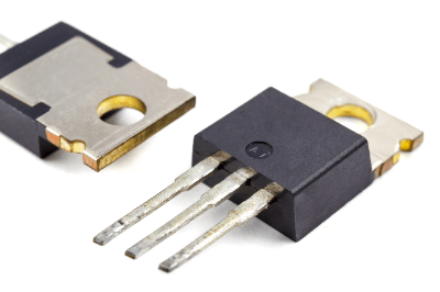
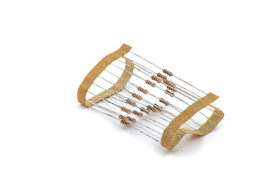
Lead Type
This type of resistor has a lead wire (metal wire). They are designed to be inserted into a hole in a board and soldered, and were once the main type of resistors.

Surface Mount Type
This type of resistor is mounted directly on the board surface. Most of the resistors currently used in circuit boards of electronic devices are of this type, and nearly 90% of them are chip resistors in the shape of a small rectangular plate. In addition, cylindrical resistors called MELF type are also used, although only a few of them are used. 

2. Classification by Resistive Element Material

Resistors can be classified into three main types according to their materials: carbon, metal, and metal-glaze.

Carbon Type
Resistors can be further classified into carbon film resistors (carbon resistors) and solid resistors. Carbon film resistors are the most commonly used low-power resistors because they are very inexpensive and can be used in a variety of cases. In most cases, the term “resistor” refers to carbon film resistors, which have an error margin of ±5%. Therefore, they are not suitable for applications that require high precision.

Metallic Type
Resistors are further divided into metal film resistors and metal oxide film resistors. Metal film resistors are resistors that use metallic materials such as nickel-chromium alloys for the film portion. Compared to carbon film resistors, metal film resistors are characterized by higher resistance accuracy and better temperature characteristics, but are more expensive.

Similarly, metal oxide film resistors use metal oxide, such as tin oxide, for the film portion. They are used for medium-power applications because of their high heat resistance.

Metal Glaze
Metal oxide or metal and glass are mixed and sintered at high temperature on an alumina substrate or similar material. It is extremely resistant to corrosion and has outstanding stability, with almost no degradation over time.

Other Information on Fixed Resistors

Lead Type Resistors

Lead type resistors are generally marked with four or five colors to indicate their resistance and tolerance. The colors correspond to numbers, e.g., 1 for brown, 2 for red, 3 for orange, and so on. T

In the Case of 4-Color Lines
The first number, second number, multiplier, and tolerance are in order from the first to the fourth line. For example, if the wire is “red-black-red-gold,” according to the color code, red is 2, black is 0, red indicating the multiplier is 10 squared, and gold represents the error ±5%. Thus, 2.0 kΩ ±5%.

In the Case of 5-Color Wire
The first number, second number, third number, multiplier, and tolerance are in order from the first to the fifth wire. If the color of the wire is “brown-green-black-black-brown,” according to the color code, brown is 1, green is 5, black is 0, black indicating the multiplier is 10 to the 0th power, so x1, and brown indicating the tolerance is ±1% error. Thus, 150Ω ±1%.

カテゴリー
category_usa

Vacuum Tank

What Is a Vacuum Tank?

A vacuum tank is a container designed to maintain a vacuum inside it.

Also known as a vacuum chamber, it is constructed from thick-walled stainless steel to withstand external atmospheric pressure, given the reduced internal pressure. These tanks are effective in minimizing heat transfer, thereby reducing heat ingress from outside and preventing heat escape from within. They are commonly used as refrigerators or insulated containers, providing excellent thermal insulation.

Vacuum tanks also isolate internal gases and liquids from the external environment, preserving them from evaporation and oxidation. This feature is beneficial for storing cooling materials and special chemicals like liquid nitrogen and liquid oxygen.

Maintaining airtightness is crucial for vacuum tanks, requiring regular maintenance and monitoring to preserve the vacuum. Timely detection and repair of any airtightness degradation or leakage are essential.

Uses of Vacuum Tanks

Vacuum tanks have diverse applications, including:

1. Semiconductors

In electronics and semiconductor manufacturing, vacuum conditions are essential for creating a contaminant-free environment. Vacuum tanks are instrumental in these processes for separating and removing gases and liquids, thus enhancing process efficiency and product quality.

2. Medical Field

Vacuum tanks are widely used in the medical industry, particularly in pharmaceutical manufacturing and storage, where certain drugs are sensitive to oxygen and moisture. They are also used in medical devices and surgical procedures for draining blood and body fluids and wound treatment.

3. Space Exploration

In space exploration, vacuum tanks are critical for safeguarding spacecraft and satellite interiors from external heat and radiation. They also serve as storage for fuel and coolant in space.

Principle of Vacuum Tanks

Vacuum tanks, designed to maintain reduced internal pressure, are typically made of thick-walled stainless steel and often equipped with exhaust and leak detection lines, sometimes including observation windows.

These tanks create a vacuum by maintaining an internal pressure lower than the atmospheric pressure outside. Airtight construction using appropriate materials and joints is essential to minimize gas leakage.

How to Select a Vacuum Tank

Key considerations when selecting a vacuum tank include its vacuum level and capacity.

1. Degree of Vacuum

For applications requiring ultra-high vacuum, check the tank’s maximum vacuum and leakage rate specifications before selection.

2. Capacity

Choose a tank based on the volume of material or liquid to be stored. Ensure the tank’s capacity is sufficient for your requirements.

Other Information About Vacuum Tanks

How to Use a Vacuum Tank

Before using a vacuum tank, inspect it for any cracks or leaks that could compromise vacuum maintenance or result in equipment damage. Ensure airtight closure of the tank, using clamps if necessary, to maintain the vacuum.

In environments where moisture and gases could adhere to the tank’s inner surface, consider pre-use procedures like heating and vacuum drying to remove these substances, as they might not desorb under vacuum conditions alone.

カテゴリー
category_usa

Sense Amplifier

What Is a Current Sense Amplifier?

A current sense amplifier is a device element that detects the value of the current flowing in an electric circuit. The current can be calculated by measuring the voltage at both ends of a shunt resistor used to detect the current. Since the voltage drop across both ends of the shunt resistor is amplified by an operational amplifier, even a slight potential difference can be seen as a large voltage. In addition, since a fixed gain is configured from the built-in resistor, it is not easily affected by temperature changes or external influences, enabling highly accurate measurements.

Uses of Current Sense Amplifiers

Current sensing is essential for safe and efficient system operation in many machines. Current sense amplifiers are used to measure the currents flowing in various machines. An example is the current flowing in electric vehicles. Standard current sensing in electric vehicles with high voltages is complex but can be measured using current sense amplifiers. Operational amplifiers usually cannot accept input voltages above the supply voltage, but current sense amplifiers can support input voltages due to their sizeable common-mode voltage range.

Principles of Current Sense Amplifiers

Current sense amplifiers are excellent device elements that measure currents flowing in various machines. Here we introduce its principle and features.

Current sense amplifiers measure the value of the flowing current by estimating the potential difference between resistors through which the current flows. This resistance is called a shunt resistor and is calculated based on a simple principle based on Ohm’s law. Even if the potential difference between the two ends of the shunt resistor is slight, it can be sufficiently measured by amplifying it with an operational amplifier. The characteristics of the shunt resistor vary depending on the position where it is placed.

  • Low-side amplifier – A shunt resistor is placed between the load and ground in a circuit. The most significant advantage of low-side current detection is that the standard code voltage is close to zero. This allows for simple implementation without the need for complex circuit design.
  • High-side amplifier – A shunt resistor is placed between the circuit’s power supply and the load. The advantage of detecting current on the high side is that it is not affected by the ground.

How to Determine the Current Sensing Resistor

One of the most critical decisions in current sensing is the selection of a current sense resistor (shunt resistor). The resistance value and wattage should be determined to obtain the desired maximum operating voltage from the maximum current that can generally be expected. When necessary, it is also essential to consider the resistor’s power dissipation before selecting the resistor’s value.

Once the current-sense resistance and wattage are determined, consider the effect of resistor tolerance. Tolerances directly affect the accuracy of the voltage and current measurements that can be taken. Also often overlooked is the temperature drift coefficient of the resistor tolerance.

Also, care must be taken in how the printed pattern is drawn from the shunt resistor to the current sense amplifiers. Since shunt resistors are usually low resistance, depending on how the pattern is drawn, the voltage drop due to the copper resistance of the pattern may also be detected, resulting in a significant error. The pattern should be separated from the shunt resistor and routed to the current sense amplifiers. In addition, the current path and voltage detection should be routed separately to eliminate errors caused by the resistance of the current path.

How to Select a Current Sense Amplifier for Current Detection

Two main types of current sense amplifiers are high-side amplifiers and low-side amplifiers. Each has its advantages and disadvantages. High-side amplifiers measure the current between the power supply and the load, so a DC voltage higher than the power supply voltage may be applied. Low-side amplifiers, in contrast, measure the current between the load and ground, so a voltage close to ground level is applied to the input pins.

When selecting current sense amplifiers, determine whether high-side or low-side current sensing will be used. For high-side current sensing, select current sense amplifiers based on the maximum advisory mode voltage required for the application and the supply voltage used. For low-side detection, select a current sense amplifier that operates at an advisory mode voltage close to 0V.

In addition, consider the direction of current detection in the system. Is recent detection limited to one direction, or does the design need to consider bi-directionality? Considering offset and gain accuracy errors based on the shunt resistance and measured current range is also essential.

カテゴリー
category_usa

Jig Grinding

What Is Jig Grinding?

Jig Grinding

A jig grinding tool is a tool used for cutting, drilling, and other machining operations. It is essential for holding the workpiece firmly during machining or guiding the cutting position.

The purpose of jig grinding is to improve processing quality, achieve uniform processing among different operators, and enhance productivity by increasing efficiency in operations.

Uses of Jig Grinding

Devices like vices, commonly employed in jig grinding, secure workpieces during cutting and drilling. For shaping materials such as sponge or plastic, jig grinding guides the cutter along a tool matching the workpiece shape, ensuring uniform processing and allowing anyone to easily and quickly work on the piece. The increasing automation in machining has led to more widespread use of jig grinding machines, including industrial robots for efficient loading and unloading of workpieces.

Principles of Jig Grinding

Jig grinding encompasses a variety of tools, from high-end and expensive models to simple and affordable jigs like those used for cutting tape. These tools are not only for holding objects but also for precise positioning and quick fixing. Modern robot-based jig grinding systems incorporate various functions to boost productivity. They may use vision cameras for workpiece inspection, input necessary machining operations, and visually inspect parts post-machining. Robots equipped with force sensors, 3D vision cameras, and artificial intelligence can perform repetitive tasks with high accuracy, handling heavy workpieces and tasks that are challenging for humans.

カテゴリー
category_usa

Linear Sensor

What Is a Linear Sensor?

A linear sensor, also known as a position sensor, measures linear displacement. These sensors come in various forms including laser sensors, wire encoders, linear encoders, and more, differentiated by their measurement principles such as laser displacement, eddy current, and electromagnetic induction.

Applications of Linear Sensors

Linear sensors are utilized across diverse sectors such as semiconductor and LCD production, electrical machinery, home appliances, the automotive industry, construction machinery, automated warehouses, and the fields of medicine, food processing, and packaging. They play critical roles in:

1. Semiconductor and LCD Manufacturing Equipment

Encoders and camera-based sensors in these industries detect the position of drive stages.

2. Food Manufacturing Plants

Encoders monitor processed food quantities and the height of molded products.

3. Construction Machinery and Automated Warehouses

These sensors provide precise positioning capabilities.

4. Medicine and Other Fields

They measure the opening degree in drainage facilities and ensure accurate positioning for medical equipment like CT scanners and operating tables.

Principle of Linear Sensors

Linear sensors operate on various principles, categorized mainly into non-contact and contact measurements:

1. Non-Contact Displacement Measurement

These include magnetostrictive sensors, laser sensors, linear encoders, and camera-based sensors, each utilizing different technologies to measure displacement without physical contact.

2. Contact-Type Displacement Measurement

Contact-type sensors like linear potentiometers and wire encoders directly measure displacement through mechanical contact.

Features of Linear Sensors

Linear sensors are distinguished by their operational type and specific features:

1. Non-Contact Type Linear Position Sensor

These sensors offer longevity, high accuracy, and speed due to the absence of mechanical wear.

2. Contact-Type Linear Position Sensor

While cost-effective, the mechanical contact leads to shorter lifespans due to brush wear.

3. Laser Sensor

Laser sensors provide high-speed, precise measurements in a compact form, though they struggle with reflective or transparent objects and environmental interference.

4. Wire Encoder

Wire encoders are durable against environmental factors but require maintenance when the wire wears out.

5. Linear Encoder

Offering high precision and speed, optical linear encoders can be affected by dirt and other contaminants.

カテゴリー
category_usa

Field Effect Transistors (FET)

What Is a Field Effect Transistor (FET)?

Field Effect Transistors (FET)

Field effect transistors (FETs) are semiconductor devices in which the current flowing between source and drain is varied by applying a voltage to the gate electrode and controlling the flow of electrons or holes through the electric field of the channel.

Field effect transistors (FET), like bipolar transistors, have three electrodes: the terminal corresponding to the base is the gate, the terminal corresponding to the collector is the drain, and the terminal corresponding to the emitter is the source, The terminal corresponding to the collector is the drain, and the terminal corresponding to the emitter is the source.

Uses of Field Effect Transistors (FETs)

Field effect transistors (FETs) are used in a wide variety of circuit fields. In digital circuits, FETs are used as elements in logic circuits. In analog circuits, they are often used in analog switches and electronic volume circuits, in addition to general amplifiers.

In particular, MOSFETs are suitable for integrated circuits because, in addition to their extremely low gate current, their structure is planar, and their manufacturing process is simpler and consumes less power than that of bipolar transistors. Large-scale digital integrated circuits, such as microcontrollers, are often composed of MOSFETs.

Field effect transistors (FETs) are also used as current switching elements in power electronics such as power supplies because of their low on-resistance and fast ON/OFF switching speed.

Principle of Field Effect Transistors (FETs)

The operating principles of JFETs and MOSFETs are different. In the following, the N-channel type is used as an example, but the P-channel type can be handled in the same way by reversing the polarity of the voltage applied to each electrode.

1. JFET

In the N-channel type, where the drain and source electrodes of the N-type semiconductor are connected to the gate electrode of the P-type semiconductor, applying a reverse voltage VGS (the gate electrode side is negative) to the PN junction between the gate and source electrodes causes a depletion layer to expand within the N-type region. Since there are no carriers in the depletion layer, the width of the current flow path (channel) in the N-type region narrows and the current ID flowing from drain to source decreases.

Based on this principle, ID can be controlled by changing the magnitude of VGS. Note that in this usage, the gate current hardly flows because of the inverse method voltage between the gate and the source. In other words, the input impedance is large.

2. MOSFET

MOS stands for metal-oxide-semiconductor. It has a three-layer structure consisting of a base semiconductor, an oxide layer as an insulating layer, and a metal electrode on top of the oxide layer. As mentioned in the previous section, there are two types of MOSFETs: enhanced type and depletion type.

In an N-channel enhancement type MOSFET with two N-type semiconductor regions in a P-type semiconductor, each of which is a drain and a source, no current flows because the drain and source are N-P-N before voltage is applied to the gate electrode. However, when a positive voltage is applied to the gate, negative charges collect under the gate through an insulating layer (oxide film) to form a thin layer of N-type semiconductor, and the drain-source interface becomes N-N-N, or continuous N-type semiconductor, allowing current flow.

The N-shaped semiconductor layer formed under the gate is called the “channel.” The thickness of the channel varies with the voltage VGS applied between the gate and the source, and the current ID flowing from the source to the drain varies with the thickness of the channel. In other words, ID can be controlled by the value of VGS. In addition, since the gate electrode is only in contact with the insulation layer, only a minute leakage current flows. This means that the input impedance is extremely large.

In the enhanced type, no current flows through the drain when VGS = 0 as described above, but in the depletion type, a thin channel is formed between the drain and source in advance to allow current to flow through the drain when VGS = 0. Therefore, Field Effect Transistors (FETs) are easy to use as amplification circuits because the drain current follows even when the signal level applied to the gate electrode is very small.

Types of Field Effect Transistors (FETs)

Field effect transistors (FETs) are classified according to their structure into junction field effect transistors (JFETs) and insulated gate field effect transistors (MOSFETs), which are indicated by different circuit symbols on the circuit diagram. There are also two types of MOSFETs: the P-channel type, in which two P-type semiconductor regions are embedded in an N-type semiconductor base, and the N-channel type, in which two N-type semiconductor regions are formed in a P-type semiconductor base, depending on the application.

Furthermore, MOSFETs can be classified into the enhancement type, in which no current flows between the source and drain unless a voltage is applied between the gate and source, and the depletion type, in which some current flows even when the gate and source are at the same potential.

覗き見防止フィルム

覗き見防止フィルムとは

覗き見防止フィルムは、パソコン、タブレット、スマートフォンなどの液晶に貼ることで液晶から発せられる光の方向をある程度統一させて、横からの覗き見を防止するフィルムです。覗き見防止フィルムを貼ることによって、他人から見られないよう重要な内容を保護し、プライバシーを保つことができます。覗き見防止フィルムは、大きさによって値段は大きく変わります。スマートフォン程度であれば1000円程度ですが、パソコンのディスプレイになると1万円程度になり、面積が大きい方が値段も高くなります。

近年ではパソコンやスマートフォンから銀行のアカウントにログインしたり、さらに振り込みを行ったりと重要な取引ができるようになりました。そこで、パスワードなどの情報の保護が重要になっており、覗き見防止フィルムの活用も増えています。 

覗き見防止フィルムの使用用途

覗き見防止フィルムは、パソコンやスマートフォンの内容を横から見えないようにする用途で使用されています。このフィルムを利用すると、パソコンやスマートフォンを電車等の混雑した状況で操作する際、基本的には正面で操作する人以外内容が見えないため、他人から情報を保護することができます。

そのため、覗き見防止フィルムは個人での使用はもちろん、公共施設や、官公庁、病院の清算用の端末機の液晶、銀行、ATMなど、不特定多数の人が出入りする場所で多く利用されています。

さらに、覗き見防止フィルムを液晶に貼っておくと、液晶が衝撃を受けた際に割れるのを防止する効果もあります。他にも、液晶からのブルーライトをカットし、目の疲れを軽減できるメリットもあります。

覗き見防止フィルムの原理

覗き見防止フィルムは、フィルム部分にルーバーと呼ばれる微細なストライプ構造を一定間隔に配置することで、光が一定方向に進むよう調節されています。ルーバーの効果で、液晶からの光が一定方向に直進するようコントロールし、正面からは画面の内容が見え、サイドからは見えない仕組みになっています。このルーバーの厚みや間隔、角度を調節することによって、覗き見防止フィルムの視認角度や透過率といった特性が変わります。覗き見防止フィルムはこのルーバーが配置されたフィルムに、さらにPETフィルムや強化ガラスなどでコーティングをして耐性をつけています。

視認できる角度は製品によりますが、48度~60度程度になっています。また、フィルムは遮光面がついている黒っぽい方が表です。裏表があるので注意してください。

覗き見防止フィルムはさらに、外部からの光の反射も抑える効果があります。外部の光によってギラついたり、指紋が反射しづらくなっています。覗き見防止フィルムを貼ることで若干液晶の色が暗くなるため、写真や映像などで色味を感じたい場合には外したほうがきれいに映ります。

覗き見防止フィルムの種類

覗き見防止フィルムは、左右方向の防止機能(180度方向)か上下左右方向の防止機能(360度方向)の二つがあります。左右方向のみの方が、画面が明るいです。画面の明るさが気になる場合は、透過率を比較して選ぶとよいでしょう。

また、スマートフォン用かパソコン用かによって仕様が異なります。

スマートフォン用の覗き見防止フィルムは、液晶に貼るタイプが主流で、はがせるタイプとはがせないタイプがあります。画面の明るさが気になる場合もあるので、はがせるタイプだと使い分けができて便利です。スマートフォンのサイズに合わせた覗き見防止フィルムを選びましょう。抗菌機能が併用されている製品もあります。

また、パソコン用は画面に取り付けるタイプが多いため、基本取り外して使用することができます。パソコン用の場合には、マグネットやプラスチック等が付属しているので、ディスプレイに取り付けしやすいものを選ぶことができます。

覗き見防止フィルムの厚みは薄いものでは0.3mm程度と貼っているのがわからないくらいの厚みです。製品により厚みに多少差がありますが、気になるほどではないでしょう。

カテゴリー
category_usa

Electrostatic Sprayer

What Is an Electrostatic Sprayer?

An electrostatic sprayer is a device used for electrostatic spraying.

Electrostatic coating is a method in which paint particles and the target to be coated are electrically charged. It is considered more efficient than conventional coating and has the advantage of reducing the amount of paint used.

However, there are disadvantages, including the ease of paint adhesion depending on the shape of the coated area. When solvent-based paints are used, sparks may occur and cause ignition, necessitating measures to prevent ignition.

Uses of Electrostatic Sprayers

As mentioned earlier, electrostatic coating is a highly efficient method, reducing paint usage and operation time. It is particularly cost-effective for mass-produced products and is widely used in coating automobiles, building materials, home appliances, and other items.

To address the challenge of paint application depending on the shape of the coated area, technology has been introduced in the automotive coating industry that uses air to adapt the coating to the shape of the part being coated.

Principles of Electrostatic Sprayer

Electrostatic coating is based on the phenomenon of electrostatic attraction.

When the target to be coated is grounded, and the negative electrode of the electrostatic sprayer contacts it, a positive charge forms on the surface of the target. This phenomenon is known as electrostatic attraction.

As the voltage applied to the electrostatic sprayer increases, corona discharge occurs at the tip of the discharge electrode. This discharge ionizes the oxygen in the air, producing oxygen anions (ozone). These oxygen anions attach to the paint particles, rendering them negatively charged.

The ion current formed by the oxygen anions carries the negatively charged particles to the target. Upon reaching the target, the paint particles adhere to the positively charged target surface through electrostatic interaction. This is the fundamental principle of painting with electrostatic sprayers.

In electrostatic sprayer coating, the ease of paint adhesion depends on the concentration of ionic current. Therefore, convex areas with higher current concentration are easier to coat, while concave areas with lower concentration are more challenging to cover.

Disadvantages of Electrostatic Sprayers

While electrostatic coating is efficient for large quantities of uniform products, it has certain drawbacks:

Uneven Coating and Peculiar Defects: Due to the reliance on electrostatic forces, non-uniform shapes may result in uneven coatings, with paint accumulating more on convex surfaces, potentially leading to defects such as “dust and dirt spots” and “yuzu-tsuki” caused by excessive voltage.

Difficulty Achieving Thin Film Thickness: Electrostatic coating cannot produce thin films; the minimum thickness is about 30 μm. Attempts to achieve thinner coatings can result in unevenness.

Challenges in Small-Quantity, High-Variety Production: Electrostatic coating involves complex processes, from cleaning to coating and high-temperature baking. Specialized coating equipment and safety measures are required, leading to substantial initial investment costs.

Paint Powder Management: Handling paint powder requires safety measures against dust explosions, and powders are prone to oxidation and contamination.

Difference Between Electrostatic and Electrodeposition Coating

The main difference between electrostatic and electrodeposition coating lies in the application method. Electrostatic coating sprays paint and relies on electrostatic forces for adhesion. In contrast, electrodeposition coating immerses the object in a paint bath and uses electrolysis to deposit a uniform coating film due to immersion in liquid paint.