カテゴリー
category_usa

Mica Capacitor

What Is a Mica Capacitor?

A mica capacitor is a capacitor that uses a natural mineral ceramic called mica as the dielectric.

These capacitors have very high heat resistance and good temperature characteristics. Mica is used in thin layers, which are peeled off one by one. The mica layer is easily cracked, making it more difficult and expensive to process than other capacitors.

In recent times, the share of ceramic capacitors has been decreasing due to their improved properties, although they continue to be preferred for audio-related applications.

Uses of Mica Capacitors

Mica capacitors were popularly used in vacuum tube amplifiers and power conditioners, especially in the 1970s and 1980s. The sound quality unique to mica capacitors has attracted attention, and some models are used in high-end audio amplifiers.

It was used in almost all electronic equipment such as radio communication equipment and electronic calculators around the time of World War II. Later, they were also used in televisions, radios, etc. However, due to their high cost, inexpensive capacitors have become the mainstream in recent years.

Principle of Mica Capacitors

1. Characteristics

Mica capacitors utilize the natural mineral mica as their dielectric material. Mica is a silicate mineral, and because it is made from a mineral, it maintains stable characteristics even at high temperatures. It also has good high-frequency characteristics.

Capacitance tolerance, which indicates the accuracy of capacitance, can be made very small, and since equivalent series resistance is small, the dielectric loss tangent can be kept small.

2. Capacitance

The capacitance of a capacitor increases as the electrode area increases. A mica capacitor consists of thinly peeled mica plates and silver foil alternately stacked in a sandwich-like structure. The purpose of sandwich layering is to make the capacitor smaller while increasing the electrode area.

Mica is an unusual mineral in that it is thin and easily peeled off, and it also has excellent electrical insulation properties. The mica capacitor was conceived based on these characteristics of mica. Some capacitors use a technique called a paper capacitor, in which the electrodes and dielectric are rolled up like a scroll to increase the electrode area.

Types of Mica Capacitors

There are two main types of mica capacitors: the stacked type, in which metal foil such as tin and mica are alternately arranged on the electrodes, and the silver paste printed on mica and layered on top of each other. The silverado-type has better characteristics because it is heat-compression bonded and is used in more situations than the stacked type.

Mica includes white mica and biotite, and its form and color vary slightly depending on the composition of the raw material. Its quality and composition vary slightly depending on the region of origin and the part used, and since it is a naturally occurring mineral, it is more difficult than other capacitors to maintain stable quality.

In addition, the process of carefully peeling off the thin layer of mica must be done by hand, so the cost is higher because of the skill required.

Other Information on Mica Capacitors

Role of Mica Capacitor

The basic structure of a capacitor consists of two electrodes facing each other with a gap between them; when a DC voltage is applied to the two electrodes, electrons momentarily gather on one electrode and become negatively charged, while the other electrode becomes positively charged due to a lack of electrons.

This state is maintained even after the application of DC voltage is stopped, and an electric charge is stored between the two electrodes. When a dielectric is inserted between the electrodes, the dielectric polarization of the dielectric increases the stored charge. Mica capacitors use mica as the dielectric.

The dielectric constant measured at 50Hz is 6.5~9, which is higher than that of other materials. Mica is also suitable for dielectrics because of its heat resistance and insulating properties and its thin film form.

Electric Double Layer Capacitor

What Is an Electric Double-Layer Capacitor?

An electric double-layer capacitor is a capacitor that uses the electric double layer formed at the interface between the electrode and the electrolyte to store an electric charge and it is characterized by its exceptionally high energy density.

Because of their high energy density, they are often compared to rechargeable batteries such as nickel-metal hydride batteries and lithium-ion batteries. Still, while batteries involve chemical reactions during charging and discharging, electric double-layer capacitors involve only physical charge adsorption and no chemical reaction.

For this reason, an electric double-layer capacitor is inferior to rechargeable batteries in terms of energy density (the amount of energy stored per unit weight or volume). Still, on the other hand, they have the advantage of output density (the amount of power that can be extracted instantaneously) and extremely low-performance degradation (life span) due to repeated charging and discharging. However, the power density (the amount of instantaneous power that can be extracted) and the performance degradation (life span) due to repeated charging and discharging are parts of the advantages.

Uses of Electric Double-Layer Capacitors

Electric double-layer capacitors are used as energy storage devices. While rechargeable batteries are suitable for applications that require a large amount of energy, electric double-layer capacitors are selected for applications that require rapid charging and discharging and where durability is required.

Specifically, they are used in backup power supplies for electronic circuits in mobile devices, printers, copiers, electric toothbrushes, solar-powered watches, etc. They are also used in the robotic power system of the asteroid probe Hayabusa and energy regeneration during the deceleration of automobiles.

Principles of the Electric Double-Layer Capacitors

The electrolytic double-layer capacitor uses the electric double layer generated at the interface of active materials to make a capacitor. Capacitance C is defined by the formula “C=εS/d.” The following measures are necessary from this formula to increase the capacitance C:

  • By increasing the surface area (S) of the active material
  • By decreasing the thickness of the electric double layer (d)
  • By increasing the dielectric constant (ε) of the electrolyte

The electrolyte is made by dissolving chemical reagents such as quaternary ammonium salts and imidazolium salts in organic solvents. Activated carbon is usually used as an active material for the cathode and anode. To increase the capacitance C, the following measures are necessary:

  • By using activated carbon with a large surface area (small particle size);
  • By using electrolytes with a small ionic radius and
  • By using organic solvents with a high dielectric constant.

The capacitors’ charging and discharging use an increase in charge at the interface between the electrolyte and electrode so that the positive and negative ions in the electrolyte are paired when they are adsorbed on their respective electrodes. When the stored charge is discharged, the ions are desorbed from the electric double layer. Electric double-layer capacitors can be cylindrical or stacked. The cylindrical type has the advantage of being easy to produce. The positive electrode, negative electrode, and separator are stacked, rolled up, and placed in a cylinder, which is then filled with electrolyte.

Other Information on Electric Double-Layer Capacitors

1. Life Span of Electric Double Layer Capacitors

Unlike batteries, electric double-layer capacitors do not undergo a chemical reaction during charging and discharging. For this reason, while the capacity of a rechargeable battery decreases significantly from the initial stage after about 1,000 cycles, the performance of electric double-layer capacitors is said, in principle, to be almost unaffected even after 1 million charge-discharge cycles. In reality, however, the capacity of electric double-layer capacitors decreases due to the following factors:

  • During charging and discharging, the capacitor generates heat due to internal resistance, which causes deterioration due to temperature rise, resulting in a decrease in capacitance.
  • As the operating environment temperature rises by 10°C, the degradation rate doubles (in an operating environment of 70°C or lower).
  • The electrolyte decomposes when the capacitor is subjected to a voltage higher than the upper operating voltage limit.

When using electric double-layer capacitors, it is necessary to consider the effect on life expectancy and pay attention to temperature rise and bias of voltage and current when used in series or parallel.

2. Disadvantages of Electric Double Layer Capacitors

The disadvantages of electric double-layer capacitors are as follows:

Dry-Up
This is caused by the evaporation of the electrolyte from the sealing section of the electric double-layer capacitors to the outside. This disadvantage can be suppressed by using an electrolyte with a high boiling point or by making the sealing section smaller.

Liquid Leakage
Leakage can occur when the butyl rubber used for sealing deteriorates. This can be controlled by reducing the size of the sealing section to prevent moisture, which causes rubber deterioration, from penetrating the inside.

AC Circuit Incompatible 
Since this product is intended for secondary electrical use, such as power backup in DC circuits, it cannot be used in AC circuits.

カテゴリー
category_usa

Trimmer Capacitor

What Is a Trimmer Capacitor?

A trimmer capacitor is a variable capacitor used for fine-tuning circuits and compensating for component variations.

The capacitance is adjusted by mechanically turning a knob with a screwdriver. They are also called semi-fixed capacitors because they are set during manufacture or service and are not shifted once they are in use. Mostly used for surface mounting, they are basically chip-type or round. They are often used to adjust the oscillation frequency of quartz crystal units.

Trimmer capacitors use the capacitance method, and capacitance can be adjusted by changing the effective surface area between electrodes, the distance between electrodes, or both.

Uses of Trimmer Capacitors

Trimmer capacitors are often used in oscillation and radio circuits, including quartz crystals, for frequency adjustment. Examples include keyless entry for automobiles, automatic ticket gates at train stations, handheld radios, power amplifiers, and RF modules for Bluetooth.

Other applications include radios, clocks, electronic pens for PCs, DVDs, hybrid ICs, and surveillance cameras. Nonmagnetic trimmer capacitors are often used in medical equipment such as MRIs.

Principle of Trimmer Capacitors

Trimmer capacitors have variable capacitance within a certain range. Like an ordinary capacitor, an insulator is sandwiched between two electrodes, which store an electric charge when a voltage is applied. The capacitance can be adjusted by moving one of the electrodes.

Air or ceramic is used as the dielectric. Trimmer capacitors have a small capacitance at the pF level because their structure does not allow them to be made with a large capacitance. Movable electrodes are often round in shape and can be shifted by rotating them with a knob or similar tool, using the center axis or outside of the electrode as a guide.

Since the surface area of the displaced electrode changes, the capacitance can be varied. During the initial setup, a screwdriver is used to adjust according to the application. Once adjusted, the capacitance is basically fixed and used without changing. When adjusting with a screwdriver, care should be taken not to apply excessive force as it may cause damage.

Structure of Trimmer Capacitor

The structure of a trimmer capacitor is the same as that of a general capacitor, except that it has a screwdriver slot and a metal rotor for adjustment. Note that because of this structure, if the soldering iron adheres to any part other than the terminal area, flux solder may enter the variable area and fix the rotor or prevent it from making contact.

Also, if the tip of the soldering iron touches the covered trimmer capacitor, it may melt or damage the capacitor.

Other Information on Trimmer Capacitors

1. How to Adjust Trimmer Capacitor

To adjust the trimmer capacitor, use a screwdriver to rotate the rotor to the desired capacitance setting. There are two types of screwdrivers for adjustment: one for manual adjustment and the other for automatic adjustment.

Ensure that the screwdriver is placed in the groove for the driver, and after a preliminary rotation of 360° or more, set the capacitance. When adjusting with a screwdriver, it is recommended to use a load of 1N or less. Applying a load greater than this may result in damage or loss of function.

The stray capacitance when adjusted with a screwdriver can be reduced by attaching the negative terminal to the ground of the circuit.

2. Colors of Trimmer Capacitors by Capacitance Rank

Some trimmer capacitors have different color cases according to their capacitance ranks. The color classification differs depending on the manufacturer, but the following are some examples:

  • Capacitors with a maximum capacitance (pF) of 3.0 +50/-0% are brown in appearance.
  • Those with a maximum capacitance (pF) of 6.0 +50/-0% are blue in appearance.
  • 10.0 +50/-0% of maximum capacitance (pF) is white.

Some capacitors have not only colors but also indications as shown below:

  • Those with a maximum capacitance (pF) of 50.0 +100/-0% have a black exterior + indication

Indication will include the shape of the terminals and whether or not a cover film is used. Thus, color-coded trimmer capacitors allow the eye to easily determine the capacitance, thus reducing the risk of using the wrong one.

カテゴリー
category_usa

Transistor Array

What Is a Transistor Array?

A transistor array is a component with multiple transistors in one package. Transistors are semiconductor devices used for switching.

The advantage of this component is that it can control multiple output relays and other devices in a small area. If mounted individually, the board area must be designed to be significant, while the board pattern should become long. However, this can cause malfunctions due to noise. On the other hand, transistor array is more economical and functional because they are smaller, lighter, and unaffected by noise.

Uses of Transistor Arrays

Transistor arrays are widely used in microcontrollers. Microcontrollers are control boards that are frequently used in home appliances such as washing machines and are an indispensable part of our daily lives.

Until the advent of transistor arrays, multiple transistors were mounted as a single item. This was not a problem, but space and cost savings were realized after the transistor arrays were introduced. In addition, one no longer had to worry about pattern routing, which reduced design effort and improved noise protection. Today, transistor arrays are essential electronic components on control boards.

Principle of Transistor Arrays

As mentioned above, transistor arrays are electronic components consisting of multiple transistors in a single package. A transistor is a semiconductor device. It is a product of three layers of P-type and N-type semiconductors, and there are PNP-type and NPN-type transistors.

The PNP-type and NPN-type transistors normally behave as insulators in a circuit, but when a voltage is applied to the middle layer, the layers at both ends become conductors. This is how transistors work.

Transistors are mainly used as outputs for microcontrollers. Before the 2000s, bipolar transistors were widely used in transistor arrays. Bipolar transistors were commonly used in transistor arrays before the 2000s because of their ability to conduct large currents and their resistance to noise. Transistor arrays consisting of several of these transistors in a row were the mainstream.

Today, high-speed, low-loss MOSFETs are the mainstream. MOSFET arrays have replaced most transistor arrays.

Other Information on Transistor Arrays

1. Internal Circuitry of Transistor Arrays

There are different types of transistor arrays depending on the transistors used inside.

  • DMOS FET: Transistor arrays that can control large currents and have low loss even when used at low currents.

  • Single Bipolar Transistor: Transistor arrays that can provide low loss when used at low currents but cannot control large currents.

  • Darlington Bipolar Transistor: Transistor arrays capable of controlling large currents, but loss occurs when used at low currents.

There is also a difference in whether the input logic is high active (current flows when a high level is an input to the input pin) or low active (current flows when a low level is an input to the input pin). There are also different types, depending on whether or not a clamp diode, which is necessary when driving a relay, etc., is built in. 

2. Source and Sink Type Transistor Arrays

There are two types of transistor arrays, depending on the type of output current, namely: source type and sink type. The source type turns the contacts on and off on the positive pole side of the load. This is the mode of operation in which current is discharged from the transistor arrays toward the load.

On the other hand, the sink type turns the contact ON/OFF on the ground side of the load. The transistor arrays draw current from the load mode of operation.

カテゴリー
category_usa

Constant Temperature Bath

What Is a Constant Temperature Bath?

A constant temperature bath is a type of apparatus used in scientific experiments.

There are two types of thermostatic chambers: one that changes the air temperature and the other that changes the water temperature (thermostatic tank). The size and specifications vary depending on the application and purpose, ranging from table-top types, large refrigerator-like types, to types in which a single room can be adjusted as a constant temperature bath.

Uses of Constant Temperature Baths

Major types of constant temperature chambers include incubators, constant temperature dryers, constant temperature water baths, and environmental test chambers (cycle testers, constant temperature/humidity chambers, etc.). Incubators are used in scientific experiments to culture microorganisms and cells. In the industrial field, incubators are used to hatch eggs, and in the medical field, incubators are used to maintain the body temperature of low-birth-weight infants. Thermostatic dryers, thermostatic water baths, and environmental test chambers are widely used in biochemistry, organic chemistry, and other fields, and are used for a variety of analytical testing purposes.

Principle of Constant Temperature Baths

A constant temperature bath basically consists of a vessel that maintains temperature, a heating (or cooling) device, a temperature sensor, and a temperature controller. Humidifiers and dehumidifiers are used to control humidity, and fans and agitators are installed to equalize the temperature inside the vessel, depending on the application. The temperature is varied by a heated humidifier, cooler, or dehumidifier, and maintained at the desired temperature by a temperature sensor.

Constant temperature baths are designed primarily to maintain a constant temperature, but depending on the application, the temperature can be programmed to rise and fall repeatedly at regular intervals, or to rise and fall at a constant gradient.

Setting an arbitrary program depends on the plugram device in the constant temperature bath itself and thus on the functionality of the individual product. If the product has a built-in communication interface, it can also be operated remotely using a personal computer. Data can be recorded directly into the constant temperature bath’s internal memory or into an external device, depending on the application.

Structure of a Constant Temperature Bath

Constant temperature baths range in size from 30 cm to several meters on a side, and can be installed in a laboratory.

The general structure of a thermostatic chamber is that it has a door and insulation to prevent temperature changes from the surrounding environment. The inside of the chamber is sealed off from the outside world. In addition, controls are installed to maintain a constant temperature for an extended period of time.

In terms of individual components, constant temperature baths are divided into two types: those that have the entire bath covered by an outer frame and those that do not. In both cases, a case is installed to hold water, and the temperature is controlled at or below the evaporation temperature of the water. In addition, when experiments are conducted at temperatures of 100°C or higher, water cannot maintain the temperature, so some devices use oil to heat the water.

Other thermostatic dryers have timers and temperature increase programs that allow the temperature and temperature increase rate to be set according to the experimental application.

Uses of Constant Temperature Baths

Constant temperature baths are generally used in laboratories, etc., and are often used in water/oil baths and constant temperature dryers.
Thermostatic water/oil baths are mainly used in chemical and biological experiments, where samples are placed in flasks and stirred to maintain a constant temperature.

The usage is simple: fill the tank installed in the instrument with water or oil and set the temperature. However, since experiments are conducted for long periods of time, care must be taken to avoid burns.

Constant temperature dryers and constant temperature-humidity baths are used not only in experiments but also in drying semiconductors, cultivating microorganisms, and drying various instruments.

The usage is simple: open the door, place a sample inside the chamber, set the temperature increase rate, target temperature, holding time, etc., and perform drying and sample observation. In addition to heating, some instruments are equipped with a cooling function that allows them to be used for low-temperature experiments. However, since they may use chlorofluorocarbons or other refrigerants, they need to be outsourced to a specialized contractor.

On the other hand, constant temperature baths using Peltier elements are also available in recent years. Peltier elements can perform cooling and heating by changing the direction of electric current. They are characterized by power savings, CFC-less, small size, and fine temperature control.

カテゴリー
category_usa

Counter

What Is a Counter?

Counters

A counter is a device, tool or part that counts. 

When counting, a small number can be easily counted and memorized, but when the number is large, it becomes difficult to do so by memory alone. Therefore, a counter is a device that counts numbers correctly on behalf of a human being.

Uses of Counters

Counters are used to help people remember numbers, and are called counters. Counters are used to count the number of cars passing by in traffic surveys, for example. Currently, it is possible to replace counters with smartphone applications.

There are also counters that are incorporated into industrial equipment as electrical components. They are called digital counters and are mainly used inside control panels at production sites.

Types of Counters

Digital counters include preset counters and total counters.

1. Preset Counter

A control signal is output when the count reaches a preset value.

Common input signals are pulse signals and contact open/close signals. Digital signals such as contact outputs or transistor outputs are used as output signals.

When it is desired to stop the output of the counter, a reset process is performed. Reset processing can be done with a pushbutton or by short-circuiting the reset terminal.

Many preset counters require an auxiliary power supply to supply electricity to the counter itself. Auxiliary power supplies can be purchased in AC or DC power supplies of your choice.

2. Total Counter

This counter has only the function of displaying the count value. It counts contact and pulse inputs and displays the count value on an output screen.

The total counter can also be reset to zero. Reset processing is performed with the pushbutton or reset terminal as with the preset counters.

Many total counters are also available with a built-in battery, eliminating the need for an auxiliary power supply. In addition to the above, there are also time counters that measure the duration of contact output.

There are also addition counters that increase the count value for each signal input and subtraction counters that decrease the count value in the opposite direction. Since there are many types of counters and their specifications vary, it is necessary to select the right counter for the right application.

Counter Principle

In the case of a counter, a human-powered pushbutton turns a character wheel to produce an output. The internal circuit only uses gears to drive the character wheel, and the reset button also manually returns the character wheel to 0.

Digital counters are mainly divided into three parts: the display section for displaying the count value, the internal circuit for receiving input signals and performing operations, and the operation section for resetting or presetting the value.

Input signals are sent to the counter in a variety of ways, including input by pushbuttons and digital input using sensors. Digital counters are generally input by contact. A pushbutton with a contact can be used to convert the input to a pushbutton input.

The internal circuitry always holds the current value. The initial value is generally 0, but it can be set arbitrarily. Upon receiving an input signal, the counter’s internal circuitry displays the current value plus one on the display.

When a preset counter is used, the output signal can be sent out by performing a preset. The preset value is compared with the current value, and if it is equal to the set value, an output signal is output.

When the operation is completed, the counter enters a state waiting for an input signal and prepares for the next operation. By repeating these series of operations, the counter counts the number of digits and continues to display the number of digits on the display.

The display section can be character wheel or digital. Most of the counters that use a character wheel are called electromagnetic counters, and they make use of an electromagnet to turn the character wheel. Electromagnetic counters have the advantage of maintaining the display even without a power source.

In recent years, counters with digital displays are also widely used. Digital displays require a power supply, but light-emitting ones have the advantage of being easy to see in the dark.

カテゴリー
category_usa

Solderless Terminals

What Is a Solderless Terminal?

Solderless Terminals
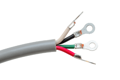
A solderless terminal is a type of terminal material used at the end of an electric wire. Solderless terminal is a method of mechanically joining a wire to a terminal by plastic deformation using a tool or other means.

There are various sizes of solderless terminals depending on the thickness of the wire to be joined and the screw diameter of the terminal block. There are also various methods of connection to the terminal block, such as screw-fastening and screw-in.

When connecting to a terminal block by screwing, there are various shapes of solderless terminals to choose from: Y-type terminals and C-type terminals are easy to work with, but there is a risk of disconnection if they are not tightened properly, so care must be taken.

Uses of Solderless Terminals

Solderless terminals are used to connect terminal blocks and wires firmly.

In general homes, they are used for terminals for wiring between outdoor units and indoor units of air conditioners. They are not visible to the naked eye because they are used by contractors for finishing work.

In industrial applications, it is used in a wide range of applications, from communication wiring to power cables. They are mainly used for terminals when cables are used.

Incomplete crimping can occur due to the use of the wrong tool or work errors. Care must be taken because incomplete crimping can increase the contact resistance of the wire, which can lead to fire or other problems.

Principle of Solderless Terminals

The fixing principle of the solderless terminal is plastic deformation of the wire terminal and the crimp terminal. Once processed, the crimp cannot be undone, and in the event of failure, the wire terminal will be cut.

Solderless terminals have two parts: the barrel and the terminal. The barrel is the part that is connected to the wiring and is large enough to accommodate all the specified wiring core wires. Both the solderless terminal and the wiring are made of a flexible metal material such as copper. They are firmly connected by matching and crushing them together with a crimping tool.

The terminal portion is the part used to connect to the control panel or control equipment. They are available in round, Y-shaped, rod-shaped, and other shapes, and are selected according to the connection destination.

Crimping wire joints has a lower risk of detachment compared to joints using insulation tape or other means.

Types of Solderless Terminals

Solderless terminals are classified into two major types: insulated crimp terminals and bare crimp terminals.

Insulated solderless terminals are crimp terminals with the barrel portion covered with an insulator. Since the insulation is already attached, there is no need for insulation treatment and bending of the connection end can be prevented.

A bare solderless terminal refers to a terminal without insulation in the barrel portion. The barrel portion after crimping is covered with an insulating cap or marked tube for insulation treatment.

There are various types of solderless terminals, including the commonly used round type, the C- or Y-shaped type, and the Y-shaped type with a claw.

Other Information on Solderless Terminals

1. How to Select the Size of Solderless Terminal

The size of the solderless terminal is selected based on the cross-sectional area of the applicable wire and the size of the hole. The engraving on the solderless terminal indicates the shape (round, Y-shaped, etc.), cross-sectional area of the applicable wire, and nominal diameter of the screw portion (e.g., for a round shape with an applicable wire of 5.5 mm2 and a nominal diameter of the screw portion, the engraving is R5.5-6).

Solderless terminals come in a variety of sizes, and if the size of the wire used and the nominal diameter of the screw do not match, a poor connection will result. Since a poor connection can cause a fire, it is important to select the appropriate solderless terminal after checking the specifications. 

2. Tools to Be Used With Solderless Terminals

Crimping pliers are used to crimp solderless terminals and connect wires.

Crimping pliers are tools that use the principle of leverage to crush the barrel portion. They are generally equipped with a ratchet function to prevent incomplete crimping.

Crimping pliers are used to crimp different objects depending on the color of the handle of the pliers. The color of the handle determines the application, and crimping pliers with red handles is used for a solderless terminal. Use the appropriate die (the grooved part of the crimp) for the barrel portion of the crimp.

カテゴリー
category_usa

MOSFET Output

What Is a MOSFET Output?

MOSFET Output relays are equipped with an LED, a light receiving element, and a MOSFE inside, and operate in the same way as conventional relay components using a combination of these elements.

Conventional mechanical relays were controlled ON/OFF by passing an electric current through a built-in coil and operating an electrical contact point by the magnetic force of the coil. In contrast, MOSFET Output relays emit light by passing a current through a built-in LED, which uses the light to generate an electromotive force in a photodetector. The MOSFET is operated by that electromotive voltage, enabling control similar to that of a conventional relay.

Similar photo MOSFET Output relays include photocouplers, phototransistors, phototriacs, and SSRs (Solid State Relay). These are collectively referred to as contactless relays or semiconductor relays, and are used differently depending on the application.

Applications of MOSFET Output Relays

MOSFET Output relays are often used in circuits that require a large current, or in phototriacs and SSRs that are good at turning alternating current on and off, rather than in photocouplers, phototransistors, and other applications.

MOSFET Output relays use light to transmit signals from the primary side to the secondary side, and since the primary and secondary sides are completely isolated electrically, they are driven by commercial power supplies or high voltage power supplies with small signals, such as microcontroller circuits. Therefore, they are used in circuits that turn on and off relatively large power loads of several A or so, and in bridging circuits such as motor drivers.

Principle of MOSFET Output Relays

When a signal current is applied to the input terminal, an LED emits light and the light-receiving element receives the light, generating an electromotive voltage. This voltage causes the gate voltage of the MOSFET to rise and the state between the source and drain of the two MOSFETs turns ON.

Then, current can flow through the source-drain of the MOSFET on the side with the higher voltage opposite the voltage between the output terminals, and through the parasitic diode of the MOSFET in the next stage. As a result, current can flow between the output terminals regardless of the electrical polarity between them.

Structure of MOSFET Output Relay

A photo MOS relay consists of three elements: an LED, a light-receiving element such as a photodiode, and a MOSFET Output.

The MOSFETs feature a structure in which two circuits are arranged in opposite directions, each connected by a parasitic diode.

Other Information on MOSFET Output

1. Application to Full-Bridge Circuits

For example, when trying to make a motor driver, it is common to construct a circuit using a full-bridge circuit. However, the biggest concern with this circuit is that when the power supply voltage is applied to both ends of the load as it is, the source voltage of the upper FET among the upper and lower FETs becomes equal to the power supply voltage. To turn on the upper FET from this state, it is necessary to prepare a separate voltage higher than the supply voltage and use that voltage to control the gate voltage of the upper FET.

However, since the MOSFET Output can operate as long as the built-in LED is lit, it can be directly driven by a signal of a few volts output from the CPU. It is also possible to completely isolate the power supply for the motor drive from the power supply for the control.

2. Types of MOSFETs

There are two types of MOSFETs: the type that is always OFF and the type that is always ON. The former can be used as make-contact relays and the latter as break-contact relays.

MOSFET Output relays can also be used as AC current switches by connecting two MOSFET sources facing each other. The conduction characteristics of photo MOSFETs are independent of the amount of input current, so that current ON/OFF control is possible even with minute input currents.

カテゴリー
category_usa

Thyristor

What Is a Thyristor?

Thyristors

A thyristor is a semiconductor device with a rectifying action. It is also called an SCR (Silicon Controlled Rectifier). Rectification refers to the conversion of alternating current to direct current. A typical electronic component with a rectifying action is a diode.

The difference between a diode and a thyristor is the gate terminal. The thyristor has a terminal called ‘the gate’. Rectifying action is only shown when current flows through the gate terminal.

Uses of Thyristors

Thyristors are used in industrial applications, such as the soda industry and electrolytic plating. The soda industry is an industry that electrolyzes salt water to produce caustic soda and hydrogen. Caustic soda is used as raw material for soap and detergent. A large DC current for electrolyzing salt water is generated by Thyristors.

In everyday life, thyristors are used for dimming LED lighting by controlling the current to the LEDs.

Principle of Thyristors

The thyristors have a PNPN quadruplex structure consisting of p-type and n-type semiconductors. The gate terminals are drawn out from n or p-type semiconductors in the middle, which are called N-gate and P-gate, respectively.

Since it has a quadruple structure, it has three junctions. Looking at the junctions from the anode side to the cathode side, the first and third junctions are forward-biased. In contrast, the second junction is reverse-biased. In this condition, a tiny current will flow if we pass the current from the anode side to the cathode side.

However, when a forward voltage is applied to the thyristors and current flows to the gate terminal, a phenomenon called avalanche breakdown occurs, and conduction occurs between the anode and cathode. This is called thyristors arc or turn-on.

After the thyristors turn on, conduction is broken when the current flowing to the anode becomes zero. This is called turn-off or quenching. Thyristor turn-off occurs naturally because the alternating current has periodic moments of zero voltage.

Other Information on Thyristors

Thyristors Uses

Thyristors are used in the power section of devices that control large amounts of power. Specific examples are listed below:

1. Rectifier
Rectification means converting alternating current to direct current. Diodes and thyristors are used for rectifiers, which are critical parts of rectifier circuits. Thyristors rectifiers are smaller and lighter than diode rectifiers but generate noise in the power system due to high frequencies. In recent years, rectifiers with transistors have been developed to suppress harmonics.

2. AC Motor Control
The equipment that controls the rotation speed of AC motors is called VVVF equipment, which consists of a converter and an inverter. The converter section converts AC power into DC power. Diodes are mainly used in the converter section.

The inverter section is a device that converts a DC power supply to an AC power supply by the reverse operation of rectification. Inside the inverter, AC power is converted to DC power once. AC current is generated by high-speed switching of the DC power supply with thyristors, etc.

カテゴリー
category_usa

Microwave Monolithic Integrated Circuit (MMIC)

What Is a Microwave Monolithic Integrated Circuit (MMIC)?

A microwave monolithic integrated circuit (MMIC) is an integrated circuit (IC) that integrates functions for microwave amplification, switching, and mixing on a single semiconductor substrate. MMIC technology is crucial for devices operating at microwave frequencies, providing a compact and efficient solution for high-frequency applications.

Unlike hybrid integrated circuits, which combine monolithic ICs and other devices on a motherboard or module board, MMICs offer a higher level of integration and reliability due to their monolithic nature, reducing the likelihood of failures associated with soldered connections.

Uses of Microwave Monolithic Integrated Circuits (MMICs)

MMICs find extensive applications in mobile terminals like smartphones, sensor-based RFID systems, transmitter/receiver ICs for base stations, and satellite broadcasting receivers. Their advantage over traditional microwave integrated circuits (MICs) lies in their enhanced reliability, miniaturization, weight reduction, and cost efficiency.

Principle of Microwave Monolithic Integrated Circuits (MMICs)

The design of MMICs involves fabricating passive components such as inductors and capacitors on semi-insulating semiconductor substrates, like GaAs and SOI, which are ideal for microwave frequencies. Active elements like bipolar transistors, which exhibit high operating speeds, are used to create the analog integrated circuits that form the basis of MMICs. The choice of semiconductor material is crucial to meet specific performance criteria, such as operating frequency and power capabilities.

Other Information on Microwave Monolithic Integrated Circuits (MMICs)

1. Examples of Microwave Monolithic Integrated Circuits (MMICs)

MMICs are commonly fabricated on substrates such as GaAs, SOI-CMOS, and SiGe. These substrates are selected for their high-frequency performance, making them suitable for applications requiring high-frequency power amplifiers and low-noise amplifiers, like those used in cellular phones and WiFi communications. The inclusion of HBTs (heterojunction bipolar transistors) in MMIC designs is favored for their consistent performance and the simplification of the power supply requirements compared to HEMT devices.

2. Example of Millimeter-Wave Application Microwave Monolithic Integrated Circuits (MMICs)

MMICs play a pivotal role in advanced communication systems, such as 5G millimeter-wave technologies and automotive anti-collision radar systems. The performance of these devices is characterized by their cutoff frequency (fT) and maximum oscillation frequency (fmax), essential for supporting the next-generation communication standards that require sub-THz frequencies. Integrating passive devices within MMICs is crucial for minimizing transmission loss, while beamforming technology, in combination with MMICs, is fundamental for the development of Beyond 5G and 6G communications.