カテゴリー
category_usa

Vacuum Pump

What Is a Vacuum Pump?
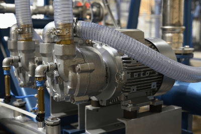
Vacuum Pumps

A vacuum pump is a device used to evacuate air or gas from a device or container to create a vacuum.

A vacuum pump consists of a pump, an exhaust port, and an intake port. Many mechanisms have been developed for pumps to create a vacuum.

The Vacuum types can be divided into low,  medium, and high. The appropriate vacuum pump to be used should be selected based on the required vacuum, the time required to reach the vacuum, and the temperature environment in which it will be used. Vacuum pump pumps can be classified into dry pumps and wet pumps, depending on whether or not oil is used.

Uses of Vacuum Pumps

Vacuum pumps are used in the manufacturing process of medical equipment and devices, food factories, electrical equipment, and semiconductors. They are also used as auxiliaries in medical and scientific equipment requiring vacuum. More than 10 different types of vacuum pump principles have been developed, each of which requires an understanding of its characteristics for proper selection.

The main applications of vacuum pumps are as follows

  • Creation of the vacuum sections in thermos bottles
  • Creating a vacuum environment when using plasma in semiconductor processes
  • When bonding food packaging materials
  • Vacuum source for scientific research equipment (evaporators, filtration, vacuum dryers, desiccators, etc.)
  • Large capacity vacuum pumps for production equipment in factories

Principles of Vacuum Pumps

Vacuum pumps are classified according to their operating principles, and the most common operating principles are described below.

1. Oil-sealed Rotary Vacuum Pumps

The oil rotary vacuum pumps are a general term for a wet pump that uses oil to make it airtight. It is also called a rotary vacuum pump.

Detailed types include rotary blade oil vacuum pumps, cam-type oil rotary vacuum pumps, and oscillating piston-type oil rotary vacuum pumps. The shapes of the rotating blades, cam, oscillating part coupled to the piston, and the part in contact with air differ, but in all types, a vacuum is created by expelling air as the rotor rotates.

As long as oil is used, the oil vapor pressure is the limit of the vacuum, but the oil works to provide stable performance and a medium vacuum can be easily obtained with a small device.

2. Oil Diffusion Vacuum Pumps

The oil diffusion vacuum pumps consist of a boiler, a jet nozzle, and a condenser. Oil heated to vapor in the boiler is injected at supersonic speed by the jet nozzle, pushing air molecules inside the pump to the exhaust port. The vaporized oil becomes liquid oil in the condenser and is reused.

3. Rotary-Blade Dry Vacuum Pumps

Rotary-blade dry vacuum pumps are oil-free vacuum pumps in which the rotating rotor and vanes exhaust the air drawn in through the inlet port as if to scrape it out. Since the backflow of air cannot be prevented, low vacuum conditions are the limit, but large pumping speeds can be obtained. 

4. Oscillating Piston Dry Vacuum Pumps

The oscillating piston dry vacuum pumps are vacuum pumps that exhaust air by pushing it out with a piston linked to an eccentric rotating shaft. Due to its structure, it cannot prevent air from flowing backward, so it is limited to low vacuum conditions, but maintenance is easy. 

5. Diaphragm Type Dry Vacuum Pumps

A diaphragm pump (membrane pump) is a pump that conveys fluid by combining the reciprocating motion of a diaphragm made of rubber, resin, or metal with a check valve. When used as a vacuum pumps, the check valve eliminates the need to use oil for airtightness and allows the pump to be used as a dry pump. With reciprocating motion, air is repeatedly sucked in from the side to be evacuated and discharged to the atmosphere to create a vacuum. 

6. Scroll Dry Vacuum Pumps

The scroll-type dry vacuum pumps are dry vacuum pumps that exhaust air through a combination of volute stator and rotor motion. The volute motion draws air to the center and exhausts it from the center.

7. Turbomolecular Pump

The turbomolecular pump is a dry vacuum pump in the form of a turbine. The turbine blades are rotated at a high speed, close to the thermal motion of molecules, to create a bias in molecular motion by the inclination of the turbine blades, thereby exhausting the air. To enable high-speed rotation of the turbine blades, the pump must be used in a certain degree of vacuum and is used in combination with other vacuum pumps.

How to Select a Vacuum Pump

In selecting vacuum pumps, the type of pump is determined based on the degree of vacuum attained, pumping time, and pumping capacity. There are three types of vacuum levels: low vacuum, medium vacuum, and high vacuum, and there are vacuum pumps for each.

1. Vacuum Pumps for Low Vacuum

For low vacuum, there are diaphragm dry pumps, oscillating piston dry pumps, and rotary blade dry pumps. Diaphragm dry pumps do not have sliding parts like rotary-blade dry pumps, so they do not generate particulate matter due to agitation and can produce a clean vacuum. The oscillating piston type has a simple structure and is easy to maintain. Rotating-blade-type pumps can achieve high pumping speeds. 

2. Vacuum Pumps for Medium Vacuum

Scroll-type and oil rotary-type vacuum pumps are available for medium vacuum applications. Many scroll-type pumps use two-stage compression to ensure efficiency and are low-vibration and low-noise. As the name suggests, oil-rotating pumps are lubricated and sealed with oil, resulting in high efficiency and good vacuum stability. 

3. Vacuum Pumps for High Vacuum

Vacuum pumps for high vacuum include the Roots type (mechanical booster). It’s vacuum pumps that rotate two rotors to suction and compress, the multi-stage Roots type vacuum pumps that integrate multiple Roots type pumps, and the oil diffusion type vacuum pumps that have a simple structure and high pumping speed. Furthermore, there are turbomolecular pumps and cryopumps for ultra-high vacuum applications.

Since there are so many different types of vacuum pumps, it is important to understand their features and characteristics and select the right one for your application.

How to Use a Vacuum Pump

For equipment that uses a vacuum, vacuum pumps are selected based on the degree of vacuum attained and the pumping time. However, because the pumping speed generally slows down as the vacuum level increases, and because some pumps for high vacuum cannot be used under atmospheric pressure conditions, vacuum pumps are sometimes used in combination rather than alone.

For example, by switching between a “low vacuum pump with a high pumping speed” and a “high vacuum pump” or using them together simultaneously, a certain amount of pumping speed can be obtained even with a high vacuum.

A concrete example is to use an oil-rotating pump to evacuate to a low vacuum range (coarse evacuation), and then switch to a mechanical booster pump to evacuate to a high vacuum (main evacuation).

In addition, two types of vacuum pumps may be connected and a pump for high vacuum may be used even at atmospheric pressure by intervening with a pump for medium and low vacuum.

カテゴリー
category_usa

Handheld Terminal

What Is a Handheld Terminal?

Handheld TerminalsA handheld terminal is a portable terminal that can easily collect data recorded in barcodes and 2D codes.
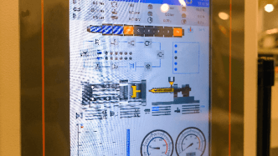
Some models can use a character recognition function to read characters in addition to barcodes and 2D codes. Functions other than data collection include data transmission/reception, data storage, key input, and screen display.

There are also a variety of types available, such as medical types that can be disinfected with chemicals, explosion-proof types specialized for explosion-proof areas, and refrigeration types for frozen warehouses, depending on the environment of the site where they will be used.

Uses of Handheld Terminals

Handheld terminals are used in a variety of business applications as portable terminals that can easily collect data, such as:

  • Pickup and package management in the transportation industry: A single android-equipped handheld terminal can send and receive delivery information, communicate with customers, and perform navigation and dynamics management.
  • Receiving and shipping management for the logistics industry: Product shelf information can be displayed on a large screen and linked to a warehouse management system to improve operational efficiency. Raw material and process management in the manufacturing and pharmaceutical fields, etc. Real-time process management can be realized through efficient and accurate input.
  • Order management and material management in the retail and restaurant industries: Orders can be shared with the kitchen and back office in real time to improve efficiency and reduce time.
  • Water, electricity, and gas meter reading: Improves work efficiency and ensures the management of personal information.

Principle of Handheld Terminals

The functions and specifications required for handheld terminals vary greatly depending on the application and scene of use, but they are mainly composed of data reading, screen display and operation, and communication functions, and the following principles are utilized.

1. Data Reading Function

The data reading function uses lasers or LEDs to read barcodes, QR codes, and other two-dimensional codes attached to products, as well as characters, and converts them into numbers, letters, and symbols according to certain rules. 

2. Screen Display

LCDs are mainly used for screen displays, which display characters, graphs, images, etc. under the control of the CPU.

3. Operation Function

Operation functions are performed via a keyboard or numeric keypad for inputting quantities, etc., or via a touch panel integrated with the screen. Input information is decoded by the CPU and recognized as letters, numbers, and symbols.

4. Communication Function

Communication functions are mainly performed via wireless LAN or Bluetooth. The terminal is connected to a host computer or other terminals via the Internet or an internal network, and the date, time, and product data read are stored in the terminal before being sent and received in real time to the host computer or other terminals.

How to Select a Handheld Terminal

Handheld terminals are available in a variety of models. In order to select an appropriate product from among the many models available, choose one based on the nature of your business, the environment in which it will be used, and the cost.

1. Business Contents

The applications required will differ depending on the nature of the business. Many handheld terminals are equipped with an Android OS, but the applications that can be used vary depending on the OS version. Check to see if the necessary apps are provided.

We also consider special requirements, such as the need for a PTT button specialized for RFID readers and intercoms. 

2. Environment of Use

Depending on the environment of the site where the product will be used, a model that satisfies special environmental conditions such as medical type, explosion-proof type, or refrigeration type may be required.

3. Cost

Cost, calculated based on budget and cost effectiveness, is another important consideration. Not only the purchase cost of handheld terminal but also the maintenance cost should be taken into account.

Other Information on Handheld Terminals

Difference Between a Handheld Terminal and a Handy Scanner

Handheld terminals are more sophisticated than handy scanners. Handheld terminals are more versatile and have a wide range of applications, while handheld scanners are used for reading merchandise POS data, reading library checkout data, etc., due to their single function but lower price.

カテゴリー
category_usa

Inkjet Printer

What Is an Industrial Inkjet Printer?

An industrial inkjet printer basically operates on the same principle as a consumer inkjet printer and prints by dropping ink in the form of dots.

However, the difference between an Industrial Inkjet Printer and a consumer inkjet printer lies in its intended use. While consumer products print text and photographs on paper, industrial printers, on the other hand, can print product information such as barcodes and expiration dates on packages and on materials other than paper.

Some industrial Inkjet Printers can also print designs on the surface of CDs, bottles, etc.

Applications of Industrial Inkjet Printers

Industrial Inkjet Printers are used in the printing industry to produce posters and signs, in the manufacturing industry to produce food, pharmaceuticals, and industrial products, and in the apparel industry, clothing manufacturing.

The unique feature of this printer is that it can print on recording media made of materials that cannot be printed on with consumer inkjet printers. For example, it can print on glass, resin, rubber, metal, cardboard, wood, and cloth.

Printing can be performed on recording media of various sizes, from small recording media such as electronic components to large recording media like signboards. It can also be used for three-dimensional recording media with curved surfaces as well as recording media with uneven surfaces.

Principle of Industrial Inkjet Printer

Industrial Inkjet Printers can be divided into the Drop-on-Demand (DOD) method and the Continuous Inkjet Printing (CIJ) method.

1. DOD Method

The DOD method is a printing technique that discharges the required amount of ink when needed. DOD methods are divided into piezo method, thermal method, and solenoid valve method.

Piezo Method
The piezo method uses the electrostriction phenomenon of a piezo (piezoelectric) device placed in the nozzle to produce an ink droplet. The advantages of the piezo method include the ability to precisely control the amount of ink ejected by controlling the voltage of the piezo element and the high durability of the head because no heat is applied.

On the other hand, the disadvantages are that the head structure tends to be complex because a piezo element is required for each nozzle, and the nozzles are easily clogged when air bubbles are introduced.

Thermal Method
In the thermal method, the ink is heated to generate air bubbles which push the ink out and cause it to drop. Advantages of the thermal method include its simple structure, which makes it easy to downsize and increase printing resolution.

On the other hand, disadvantages are that thermal degradation of ink tends to occur, head life is short due to heat, and nozzles are easily clogged due to ink drying.

Solenoid Valve Method
In the solenoid valve method, the solenoid valve is momentarily opened while pressure is applied to the ink by a pump, which causes the ink to drip. The advantage of the solenoid valve method is that the ink can be dispersed far by the pressurization.

However, it tends to produce larger ink particles, leading to lower print quality.

2. The CIJ Method

The CIJ method is a printing method in which pressurized ink is circulated in the printer and ejected from the nozzle at the precise moment. Volatile ink is ejected from a single nozzle, and since ink is constantly circulated in the CIJ method, volatile ink with excellent drying properties can be used.

Structure of an Inkjet Printer

1. DOD Method

The mainstream printer is equipped with a head that ejects ink, a carriage on which the head is mounted, a mechanism that moves the carriage in the main scanning direction, and a mechanism that moves the recording media in the sub-scanning direction. During printing, the carriage moves in the main scanning direction and the recording media moves in the sub-scanning direction alternately.

2. The CIJ Method

This printer features a fixed head on the print media carrier, and it prints on the media as it is transported by the conveying mechanism.

カテゴリー
category_usa

Programmable Display

What Is a Programmable Display?

Programmable DisplaysA programmable display is a display/operation device with a built-in computer that can be programmed.
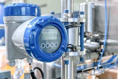
Most of them are in the form of a touch panel. In addition to display and operation, a wide range of products with communication and logging functions are also available.

In most cases, the internal program is developed using dedicated software sold by the programmable display manufacturer.

Uses of Programmable Displays

Programmable displays are used in a wide range of applications, from everyday life to industrial fields.

The following are examples of programmable display applications:

  • Vending machines
  • Fueling machines at gas stations
  • Commercial equipment such as ATMs
  • Exhaust gas measurement equipment
  • Factory automation equipment
  • Car navigation systems for automobiles and buses
  • Navigation equipment for ships

A familiar application that has been used for some time is ATMs. Push buttons and guidance are displayed on a touch panel to facilitate operation.

In industrial applications, ATMs are used in conjunction with programmable controllers (PLCs) and other control devices to display information on machinery and equipment. It is generally possible to perform operations as needed.

Principle of Programmable Displays

Programmable displays are mainly composed of a display function, an operation function, and an internal control function.

1. Display Function

The display function shows a screen on the display. It displays information on the status of mechanical devices and operating instructions. In the case of machinery, lamps and meters are displayed, along with a simple system diagram to assist in operation management. 

2. Operation Function

The operation function is a function that can be operated by pressing a finger on the touch panel. If the display is programmed to show operation buttons, the buttons can be operated as needed. When a button is pressed, the computer detects it and feeds back to the control device. 

3. Internal Control Function

The internal control function is a function that performs status monitoring and logging. In recent years, products with communication and network functions are also available.

Other Information on Programmable Displays

1. How to Use Programmable Displays

Programmable displays require editing software sold by the manufacturer. Consider purchasing software for editing.

In addition, programmable displays often have a separate CPU that performs arithmetic operations, and in most cases, the signal cable connecting the CPU and programmable display is an international standard. Because of the international standard, the CPU and programmable display may be made by different manufacturers.

The following is an example of the communication method used.

RS232C
RS232C signals are the oldest serial communication used. The transmission distance is within 15 m, which is a relatively short distance communication. The number of units that can be connected is limited to one CPU to one display unit.

RS422
RS422 signals have a maximum transmission distance of 1200m and are upward compatible with RS232C serial communication. However, the number of connectable units is limited to a total of 10 CPUs and indicators.

RS485
The RS485 signal is a serial communication that is upward compatible with the RS422 signal. It has the advantage of allowing a larger number of units to be connected while maintaining the same transmission speed.

Ethernet
Ethernet (LAN) communication is the most common method of communication for Programmable Displays in recent years, and is also used to connect PCs and other devices to the Internet via a wired connection, allowing a virtually unlimited number of devices to be connected. It also has the advantage of allowing direct, permanent connections to PCs and the Internet.

However, the maximum transmission distance of a LAN cable is 100 meters. When configuring a network in a high-rise building, for example, a relay method using a HUB is used. In large factories where it is difficult to set up a relay point, a media converter is used to convert LAN signals to optical signals for transmission. 

2. Programmable Displays in English

Programmable display is generally called HMI (human-machine interface).

The meaning of HMI is “a device for exchanging information between humans and machines,” and HMI includes the mouse, keyboard, and display on a PC.

カテゴリー
category_usa

Electromagnetic Field (EMF) Meter

What Is an Electromagnetic Field Meter?

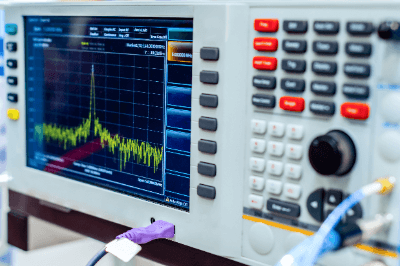
An Electromagnetic Field (EMF) Meter is an instrument used to measure the strength of electric fields.

It is mainly used to measure the strength of radio waves received by radios and televisions, as well as to measure radio waves emitted by electronic devices. In recent years, there has been a significant increase in the us of electronic devices that emit radio waves.

The risk of radio interference among electronic devices and the potential impact of radio waves on the human body are both on the rise. As such, there is a great need for Electromagnetic Field (EMF) Meters that can accurately measure the electric field strength.

Applications of Electromagnetic Field (EMF) Meter

The Electromagnetic Field (EMF) Meter is designed to measure the strength of radio waves,  and so is used to investigate the installation location of devices that receive radio waves and to inspect the safety of devices that output radio waves.

When investigating the installation location of equipment that receives radio waves, EMF Meters are useful for assessing antenna installations for TV broadcast reception and identifying potential interference with TV reception. In recent times, there has been growing demand for measuring WiFi radio wave strength.

Electromagnetic Field (EMF) Meter is used in safety inspections of equipment that outputs radio waves. It helps to reduce the risk of radio interference from equipment that generates radio waves and ensure compliance with electromagnetic field bio-safety guidelines, minimizing potential adverse effects of radio wave on the human body.

Principle of Electromagnetic Field (EMF) Meter

The most common method of measuring the strength of radio waves is to use an Electromagnetic Field (EMF) Meter to measure the voltage induced in an antenna with a known gain. The measured value is converted to an antenna with an effective length of 1 m and expressed in [dBμV/m].

1. Radio Wave Strength in Space

Electromagnetic Field (EMF) Meter has different measurement methods depending on the application. To measure the radio wave strength in a space, an electric field probe is simply directed towards the target device. Typically, the electric field probe uses an EO modulator (electro-optic modulator) to detect the intensity of the radio waves.

In the absence of an electric field, light input from a light source in the field probe passes through an optical fiber, is reflected by an EO crystal, and then passes through another optical fiber before being output.

However, when an electric charge is present, the EO crystal alters the refractive index of the light. Consequently, the output light exhibits a different refractive index than the input light. By converting the modulated light into intensity information using a photodetector, the Electromagnetic Field (EMF) Meter measures the strength of the electric field.

2. Radio Wave Absorption in the Human Body

In order to examine the radio wave absorption efficiency of the human body, etc., a device called a phantom must be inserted between the device under test and the electric field probe.

The phantom has the same electrical characteristics as the human body. The field probe of the Electromagnetic Field (EMF) Meter consists of an optical fiber, an EO crystal, and a glass tube covering it. The EO crystal exhibits the EO effect, in which the refractive index of light changes depending on the electric field present. The modulated signal is then detected by a photodetector.

Other Information on Electromagnetic Field (EMF) Meter

1. Electromagnetic Field (EMF) Meter Kits

The major difference between commercially available inexpensive assembled kits of Electromagnetic Field (EMF) Meter and those sold by the manufacturer is the significant difference in performance, convenience, and versatility. For example, in the case of inexpensive kits, the display is an analog pointer meter.

On the other hand, the manufacturer’s Electromagnetic Field (EMF) Meter has a color LCD display, can store the obtained data in memory, and can communicate with other devices. Therefore, it can be said that Electromagnetic Field (EMF) Meter kits are more for educational or temporary use.

2. Electromagnetic Field (EMF) Meter App

In recent times, WiFi signal strength can be measured with Electromagnetic Field (EMF) Meter apps. However, a little care is needed in the settings. When setting up a wireless network, the coverage area will hardly change.

However, the signal strength is weakened as it passes through obstacles like furniture and walls. So is interference caused by other wireless networks in the vicinity, causing the WiFi signal to progressively weaken as one move away from the source router.

When users get a strong signal, they get fast page loads and instant downloads. In order for the router to send a strong signal where it is needed, it is important to choose the right location and configuration of the router for the best results.

Recently, there are apps that display a visual map of the router wireless range. These apps also show information about other WiFi networks and the field strength of the WiFi signal. They visualize the signal strength of the wireless network as a handy heat map to assist in determining where to place the router.

カテゴリー
category_usa

Encoder

What Is an Encoder?

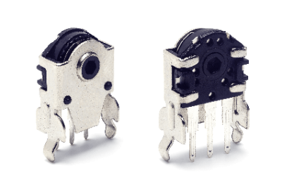
Encoders

An encoder is a device that converts changes in position into electrical signals and outputs them.

Encoders that measure rotation angle are called rotary encoder, while those that measure linear displacement are called linear encoder.

Methods for measuring position change can be classified into incremental and absolute methods. Light, magnetic force, electromagnetic induction, etc. are commonly used for measurement.

Uses of Encoders

Encoders are mainly used in machines that use motors, among which stepping motors and servo motors are typical motors that use encoders.

1. Stepping Motors

Stepping motors are motors whose rotational speed and angle can be accurately controlled by pulse signals.

The interval between pulses and the number of pulse signals applied to the motor determine the angle and speed of rotation, enabling accurate positioning, which is why stepping motors are used in manufacturing and other fields.

Not all stepping motors use encoders. There are two types of stepping motors: open-loop stepping motors, which do not use encoders or feedback control, and closed-loop stepping motors, which use encoders and feedback control.

The open-loop method is a simpler system than the closed-loop method, but it always applies the maximum current to prevent “stalling,” which is the inability to keep up with the pulse speed.

2. Servo Motors

A servo motor is a motor that has a mechanism to maintain a constant speed of continuous linear or rotational motion by precisely controlling the distance traveled and angle of rotation in a single control.

It is a three-piece set consisting of encoders, a brushless AC motor (the mainstream) or a DC motor, and a servo amplifier. AC motors are currently the most common type of motor used in machines that require precise motion control. Examples include industrial robots, automobiles, elevators, and automatic guided vehicles. They are used in many factories, especially now that factories are becoming more and more automated.

When selecting encoders, consider measurement accuracy, resolution, reaction time, size and shape, durability against vibration and shock, and protection against the operating environment.

Principle of Encoders

Encoders are classified into optical, magnetic, and electromagnetic induction types according to the detection method.

1. Optical Encoders

Displacement can be measured by shining light on a rotating disk with evenly spaced holes attached to a rotating shaft and detecting the period of light passing through the holes. Since light has little effect on machines, it is widely used in general.

Optical encoders can be classified into two types according to the output signal: incremental and absolute. Each method is explained below.

  • Incremental method
    The incremental method measures position displacement by measuring the number of times light passes through a hole in a rotating disk.
  • Absolute method
    The absolute method measures position displacement by detecting absolute position signals assigned to each hole of the rotating disk.

2. Magnetic Encoders

Displacement is measured by utilizing the magnetic field of a magnet attached to the rotating shaft, which fluctuates due to rotation.

3. Electromagnetic Induction Encoders

Displacement is measured by detecting electromagnetic induction generated by a coil mounted around a rotating shaft.

カテゴリー
category_usa

Flowmeter

What Is Flowmeter?

flowmeter

A Flowmeter is a device used to measure the volumetric or mass flow rate of a fluid flowing through a pipe.

Many measurement principles have been developed to properly measure various types of flow depending on conditions such as pressure and temperature. Flow types include gas, liquid, and multiphase flows.

Some products can be installed outside of the piping to measure flow. However, many flowmeters are designed to be installed inside the piping for flow measurement. Therefore, the installation of a flowmeter should be carefully considered either before the piping is installed or during the design phase.

Uses of Flowmeter

Flowmeters are widely used in manufacturing where fluids are used, including chemical and petroleum plants, automotive, semiconductor, pharmaceutical, and food industries.

More than ten (10) different operating principles have been developed for flow meters, and the appropriate flow meter must be selected according to the fluid being handled.

Flowmeters installed in pipes can disrupt the flow. Therefore, the selection should be based on consideration of the extent of this impact. The frequency, time, and cost of maintenance should also be considered.

Types of Flowmeters

The following is a brief introduction to the types of flowmeters and their respective mechanisms, principles, and advantages.

1. Positive Displacement Flowmeter

A positive displacement flowmeter consists of a pipe with the same inside diameter as the piping to be measured, a rotor, and a rotation detector. The fluid flowing through the pipe rotates the rotor, and the flow rate is measured by detecting the rotation speed.

The structure is simple and highly accurate, but the use of gears can lead to problems such as entanglement.

It is used for for measuring the flow rate of fluids like fuel oil and lubricating oil, which have relatively stable densities. Due to its high accuracy, it is well-suited for applications such as fuel oil trading.

2. Coriolis Flowmeter

The Coriolis flowmeter consists of two U-tubes, a vibrating machine, and a force sensor. The Coriolis flowmeter utilizes the principle of Coriolis force, in which two oscillating U-tubes with fluid flowing through them generate forces in opposite directions to each other.

While the Coriolis flowmeter has the disadvantage of being long due to its measurement principle, it does well at directly measuring mass flow. It has high accuracy and responsiveness, and is widely used when the density of a fluid is also to be measured at the same time.

On the other hand, it is less effective in environments with vibrations or when measuring fluids that contain bubbles.

3. Ultrasonic Flowmeter

An ultrasonic flowmeter consists of an ultrasonic generator and a measuring instrument. The flow rate is calculated by measuring the propagation time of ultrasonic waves and the Doppler effect caused by the reflection of ultrasonic waves. This flowmeter can measure from the outside of the piping.

It has the advantage of non-contact fluid flow measurement, allowing the flowmeter to be retrofitted onto existing piping. It can also be installed cost-effectively, even on large-diameter piping.

However, it is not well-suited for applications that require highly accurate flow measurement due to errors caused by factors such as pipe wall thickness.

4. Electromagnetic Flowmeter

Electromagnetic flowmeter calculates the flow rate by measuring the electromotive force generated by the coil component within the device. This electromotive force is influenced by the velocity of a magnetic material placed inside the fluid to be measured.

Many of these meters do not need to be installed in the pipe, and are used when maintenance costs for in-pipe flowmeters, such as those used for contaminated water, are high.

Electromagnetic Flowmeter is used to measure the flow rate of slurry mixed with solids because it has no moving parts and does not obstruct the flow of fluid. However, it cannot measure non-conductive fluids, such as oil.

5. Thermal Flowmeter

A thermal flowmeter consists of two temperature sensors and a heater. It calculates the flow rate by measuring the difference between the fluid’s temperature before and after it is heated by the heater. This measurement is then converted into a flow rate. The thermal flowmeter is known for its ability to handle a wide range of temperatures.

Thermal flowmeter can measure corrosive gases since it is a non-contact gas flowmeter. In addition, there is almost no pressure loss and mass flow rate can be measured. However, it may not be suitable for the measuring theflow rate of gases that already contain contaminants.

6. Area Flowmeter

In an area flowmeter, a float within a vertically tapered tube interrupts the flow from bottom to top, resulting in a pressure difference before and after the float. The meter rests at a position where the weight of the float and the force of the pressure difference are balanced. By reading this position, the flow rate can be determined.

It is used to measure the flow rate of liquids, gases, purge fluids, and more. Its straightforward construction makes it cost-effective, although it does not provide very high measurement accuracy.

7. Turbine Flowmeter

The turbine flowmeter is positioned within the flow and calculates the volumetric flow rate based on the number of revolutions of the impeller. It utilizes the fact that the rotational speed of the impeller, which has an axis parallel to the flow, is directly proportional to the flow velocity.

The lightweight design allows for a high degree of freedom in installation. Due its lightweight, inexpensiveness, excellent repeatability, and responsiveness, it is well-suited for measuring large volumes of fluid. However, it has a short-service life due to bearing deterioration.

8. Differential Pressure Flowmeter

Differential pressure flowmeter uses an orifice to create a pressure loss and measures the flow rate by utilizing the pressure difference between the primary and secondary sides.

It is characterized by its low-cost and wide range of applications. Actual flow calibration is not required.

9. Karman Vortex Flowmeter

The Karman vortex flowmeter consists of an obstacle designed to generate Karman vortex and a vortex measuring instrument. The flow rate is calculated by measuring the Karman vortex.

Karman vortex is a regular vortex generated in the wake of an obstruction.

Karman vortex flowmeter can measure a wide range of fluids since there are no mechanical operating parts or electrodes. However, it cannot be used in high-vibration environments due to the length of straight pipe required and the possibility of malfunctions caused by vibration.

It is used to measure steam and clean water.

10. Vortex Flowmeter

A vortex flowmeter is a flowmeter that uses the Karman vortex. A Karman vortex is an alternating sequence of regular vortices that occur downstream of an object (vortex source) placed in the fluid flow.

11. Flow Cell Flowmeter

A flow cell flowmeter is a type of orifice flowmeter that generates differential pressure by installing an orifice in the piping through which water or air flows and measures the differential pressure using a float installed in the tributary stream.

カテゴリー
category_usa

Line Scan Cameras

What Is a Line Scan Camera?

A line scan camera is a camera that captures an object in a line and combines it into a single image.

Area sensor cameras, which are often compared, capture the entire field of view at once.

A line scan camera captures a flat image by continuously moving the object perpendicularly to a row of line sensors, or by moving the camera.

Unlike an area sensor camera, a line scan camera can capture slight pixel-by-pixel changes when acquiring a horizontal image.

Uses of Line Scan Cameras

Objects for which line scan cameras are suitable include those that are large, require high precision resolution, are long and continuous, and have a three-dimensional appearance.

For example, when photographing a large object, an area sensor can be used to take pictures by dividing the object into sections, but in this case, multiple images must be stitched together. On the other hand, using a line sensor, the image can be captured as a single image and does not need to be stitched together.

Specifically, line scan cameras are used for a wide range of purposes, from inspections of social infrastructure such as roads and exterior walls to industrial inspections of non-woven fabrics, gears, semiconductor parts, etc. In addition, they are also used in the analysis of works of art, and in the sorting of fruit that had previously been inspected visually.

Principle of Line Scan Cameras

Like an ordinary camera, a line scan camera converts light entering through a lens into an electronic signal by forming an image on a CCD, CMOS, or other imaging element and outputs the signal as an image.

The camera continuously captures images by moving the subject vertically to the imaging element, which consists of a single row of line sensors. Many images are then combined to obtain a continuous image.

Line scan cameras can be broadly classified into models that can acquire monochrome images and models that can acquire color or invisible ray images.

Models that can acquire color images have about 1~3 rows of line sensors and are multilayered. This is because only one color’s information is available from each sensor.

In a 3-row color sensor, a particular pixel is captured by three image sensors that can acquire blue, green, and red color information. On the other hand, with a single-row color sensor, only a single pixel is captured by a single image sensor, so only a single color’s information is acquired. And since the color information of one specific pixel is estimated from the surrounding color information, the color accuracy is inferior to that of a three-row color sensor.

Selecting Line Scan Cameras

What is important in selecting line scan cameras is to make a total judgment of the resolution, exposure control, high-speed compatibility, sensitivity, and other factors of the target system to be handled.

1. Exposure Control

Old line scan cameras do not have exposure control, and the brightness of the light source is manually changed in response to speed fluctuations. By using an electronic shutter, the exposure time can be automatically changed to capture images at the same brightness even if the speed changes.

2. High-Speed Support

This is judged by throughput, which represents data processing capacity. Cameras with the highest speed level are now commercially available.

3. Sensitivity

Conventional line scan cameras require a strong light source because they can only take an exposure time of one line scan. Therefore, the sensor itself is highly efficient with an aperture ratio of 100%. Some cameras use time-delay integration technology to increase sensitivity by dozens of times or more, making them suitable for locations where light levels cannot be increased or for high-speed scanning.

4. Shading Correction

Modern cameras can compensate for small differences in sensitivity within a pixel in real-time in the camera. With this tool, shading correction, which is the correction of light intensity variation in the width direction due to uneven illumination, can be performed.

カテゴリー
category_usa

Spring Contact Probe

What Is a Spring Contact Probe?

A spring contact probe is an electrically conductive probe.

A spring contact probe can be used to inspect the continuity of printed circuit boards and electronic components without the need for soldering, connector connection, or other fixing. The shape of the probe can be selected according to the inspection target.

The spring-loaded structure allows the probe to make contact with the electrode to be inspected with an appropriate load.

Uses of Spring Contact Probes

A spring contact probes are used for continuity testing of electronic components.

The inspection targets include semiconductors, liquid crystal panels, circuit boards, connectors, capacitors, sensors, batteries, and other components.

In addition to simple inspections of disconnections and shorts in these components, spring contact probes can be used in a wide range of applications, such as current flow and high-frequency measurement. For example, to inspect ICs, spring contact probes are placed on the printed circuit board on the side of the inspection equipment and contacts the IC from above, enabling quality inspection without fixing it in place.

カテゴリー
category_usa

Oscilloscope

What Is an Oscilloscope?

Oscilloscope

An oscilloscope is an instrument that outputs electrical signals as waveforms on a screen, and is characterized by the ability to observe signal changes over time in two dimensions.

Oscilloscopes are broadly classified into analog oscilloscopes and digital oscilloscopes.

1. Analog Oscilloscopes

Analog oscilloscopes observe input signals by scanning an electron beam over the tube surface of a cathode-ray tube to draw waveforms. The input signal to the oscilloscope is immediately displayed with a short delay.

2. Digital Oscilloscopes

Digital oscilloscopes convert input signals into digital data using an A/D converter, store the data in memory, and then display the waveforms on a display. Unlike analog oscilloscopes, data collection is discrete, so data is complementary and displays as a smooth curve.

Uses of Oscilloscopes

Oscilloscopes display electrical signals as waveforms, allowing you to visually check the operation of electronic circuits. By using an oscilloscope, it is possible to check the signal waveforms in an electronic circuit and verify that the circuit is operating as intended.

When verifying high-speed digital circuits, signals must be captured with reliable timing that is not affected by digital signal fluctuations (jitter), and oscilloscopes are used to set the timing.

Oscilloscopes are also useful in repairing electronic equipment because they can trace the signal waveforms of various parts of an electronic circuit to locate the faulty part if the cause of the equipment failure is in the electronic circuit.

Principle of Oscilloscopes

In a conventional analog oscilloscope, the signal input from the probe is transmitted to the oscilloscope’s vertical amplification circuit. The signal is attenuated or amplified in the vertical amplifier circuit and then transmitted to the vertical deflector plate of the cathode-ray tube.

The voltage applied to the vertical deflector plate scans the electron beam up and down. This sequence of events is the principle behind oscilloscopes. The input signal is simultaneously transmitted to the trigger circuit, and the electron beam starts scanning horizontally the moment the signal matches the set trigger condition.

In a digital oscilloscope, the input signal is converted to digital data by an A/D converter, and the data is sequentially stored in memory. Then, after a predetermined period has elapsed from the point when the input signal meets the trigger condition, it stops storing new data.

As a result, the above memory records the signals before and after the timing when the trigger condition is met, and these signals are displayed as waveforms on the display. In other words, signal waveforms before the trigger can also be observed.

The data in the memory can also be used for waveform analysis, e.g., frequency analysis of signals by FFT operation. Furthermore, the data can be output to a memory card for analysis and data storage on a PC.

How to Select an Oscilloscope

When selecting an oscilloscope, it must have sufficient specifications for the application. Specifically, frequency response, sampling rate, number of channels, memory length, and available probe types should be considered.

In addition to the basic use of oscilloscopes for observing waveforms, current oscilloscope applications are expanding to include timing verification, waveform analysis, and compliance testing, and the measurement range and functionality are increasing accordingly. As a result, there is a need to select a model with functions suitable for the intended use.

How to Use an Oscilloscope

In addition to observing voltage variations over time, oscilloscopes can also measure the frequency of repetitive signals and draw Lissajous curves. Oscilloscopes are widely used for testing electronic circuits, waveform visualization of video and audio signals, testing response characteristics of power devices, measuring the timing margin of high-speed digital circuits, and evaluating mechatronics products.

Preparation for measurement includes phase adjustment of probes and skew adjustment between probes. Especially when current and voltage probes are used together, skew adjustment is essential because of the significant delay time of current probes. One should also wait about 30 minutes after power-on before measuring to ensure sufficient measurement accuracy.

The trick to observing the desired waveform is to adjust the trigger. With analog oscilloscopes, the only adjustment factors are slope selection, trigger level, and trigger delay, but with digital oscilloscopes, in addition to these factors, various trigger conditions, such as pulse width and interval, can be set.

Additionally, sequential triggers, which capture signals when multiple trigger conditions are satisfied, are also available.

Other Information on Oscilloscopes

1. Features and Differences Between Analog and Digital Oscilloscopes

The features of both types of oscilloscopes can be summarized as follows:

Analog Oscilloscope

  • Excellent real-time performance and short dead time between capturing and displaying a new signal.
  • The frequency of occurrence of the same waveform can be determined by the brightness of the signal.
  • Not suitable for observation of one-shot phenomena or phenomena that are not frequently repeated.
  • Requires photographic equipment to save observation results.
  • Analysis using waveforms is not possible.

Digital Oscilloscope

  • The supplemental display of one-shot phenomena is possible.
  • Observation results can be handled as electronic data for easy storage.
  • Waveforms can be handled as digital data and analyzed by a processor.
  • Long dead time for signal processing, so actual observation time is relatively short.
  • Waveform frequency information is lost in repetitive waveforms.

Today, there are no analog oscilloscopes available for industrial measurement applications, and digital oscilloscopes are the choice for almost 100% of applications.

This is possible because of readily available high-speed A/D converters and processors for waveform processing, along with tech improvements that address digital oscilloscope limitations, resulting in affordable, highly functional products.

2. Points to Note About Oscilloscopes

There are several points to note when using an oscilloscope to observe correct waveforms. In particular, it is important to select a model with a frequency response that sufficiently covers the frequency band you wish to measure.

The frequency response of an oscilloscope is defined as the frequency at which the amplitude falls to -3 dB. So, for accurate amplitude measurement, a model with a frequency response of about 5 times the frequency of the signal under test should be selected.

Additionally, the data sampling frequency of a digital oscilloscope must also be taken into consideration. If the sampling frequency is less than twice the frequency of the signal under test, aliasing will occur and false waveforms will be displayed.