カテゴリー
category_es

Sistemas de Inspección de Superficies

¿Qué son los Sistemas de Inspección de Superficies?

Los equipos de inspección de superficies son empleados en las líneas de producción de fábricas con el propósito de examinar productos.

Su función principal radica en identificar productos defectuosos y detectar piezas con imperfecciones.

Usos de los Sistemas de Inspección de Superficies

Los sistemas de inspección de superficies se utilizan para la inspección de productos en diversos campos. Por ejemplo, se utilizan para inspeccionar productos que se fabrican en serie, como películas, vidrio y láminas de metal.

Los sistemas de inspección de superficies pueden utilizarse para evitar el envío de productos defectuosos mediante la detección de defectos en los productos a partir de los datos de imagen obtenidos al tomar una imagen de la superficie de cada producto. Sin embargo, los elementos que deben inspeccionar los sistemas de inspección de superficies varían de un producto a otro.

Para los productos en los que la suavidad es importante, como las películas y el vidrio, se detectan las irregularidades, mientras que para las chapas metálicas, se detectan los arañazos finos.

Principio de los Sistemas de Inspección de Superficies

Los sistemas de inspección de superficies detectan los defectos basándose en los datos de imagen obtenidos a través de una cámara. Por lo tanto, un equipo de inspección de superficies consta de una unidad de inspección que comprende un receptor de luz y un proyector de luz, y una unidad de control para el procesamiento de imágenes, que incluye un ordenador. En la sección de inspección se suele utilizar una cámara CCD como receptor de luz.

El proyector se refiere a la fuente de luz, y se utilizan lámparas fluorescentes, LED y lámparas halógenas en función de la aplicación. La luz emitida por la fuente luminosa, el reflector, se refleja o transmite sobre la superficie del objeto a inspeccionar, y es captada por la cámara CCD en la parte receptora de luz y convertida en una señal eléctrica.

Las señales de la cámara CCD se procesan en la unidad de control y los defectos pueden detectarse y determinarse a partir de los datos de la imagen. El método utilizado para detectar defectos en los datos de imagen consiste en comparar los datos obtenidos con los de un producto sin anomalías, y juzgar un defecto como tal si se detecta un cambio que supere un valor umbral. Por ejemplo, los sistemas de inspección de superficies para papel soporte de impresión utilizan convencionalmente formas de onda analógicas en lugar de datos de imagen.

Con este método, los defectos finos podrían no ser detectados dependiendo del ajuste del umbral, o un tono de fondo podría ser juzgado erróneamente como un defecto. El uso de datos de imagen resuelve estos problemas, ya que se puede realizar un juicio detallado en función del tamaño del píxel.

Más Información sobre los Sistemas de Inspección de Superficies

1. Diseño Óptico de los Sistemas de Inspección de Superficies

En los sistemas de inspección de superficies, la luz se emite desde una fuente luminosa, el proyector, y se refleja o transmite sobre la superficie a inspeccionar. Existen cinco tipos de reflexión y transmisión: “reflexión directa”, “reflexión difusa”, “transmisión directa”, “transmisión difusa” y “transmisión por dispersión”.

Como cada método tiene características diferentes, es importante seleccionar el método en función de si se desea detectar “defectos” o “irregularidades” en la inspección de superficies.

2. Cámaras y Proyectores en los Sistemas de Inspección de Superficies

La precisión de la cámara de la unidad de inspección es un factor muy importante en los sistemas de inspección de superficies. Es importante tener en cuenta que si la cámara no funciona correctamente de acuerdo con su precisión, cualquier zona anormal pasará desapercibida.

El rendimiento del proyector que hace brillar la luz sobre el objeto que se va a inspeccionar también tiene un efecto significativo en el rendimiento de imagen de la cámara. Para garantizar que la luz incida uniformemente sobre la superficie del objeto de inspección, es decir, sobre la superficie de inspección, se utiliza una fuente de luz como, por ejemplo, una barra de luz con un difusor como proyector que incida uniformemente sobre una amplia superficie del objeto de inspección. La luz de rejilla (luz de hendidura) también puede utilizarse como fuente de luz para inspeccionar superficies curvas y detectar defectos diminutos.

3. Procesamiento de Imágenes de los Sistemas de Inspección de Superficies

En los sistemas de inspección de superficies, la luz captada por el objetivo de la cámara CCD en la sección de inspección se proyecta como datos de imagen en el sensor de imagen y se transmite al ordenador que procesa las imágenes en la sección de control. Los procesos generales del procesamiento de imágenes son el preprocesamiento, el procesamiento de mediciones, el juicio sobre si existe o no una anomalía y la salida.

Dado que los datos de imagen capturados por el sensor de imagen contienen mucho ruido, los datos de imagen utilizados para el proceso de medición son una imagen limpia con ruido reducido mediante preprocesamiento, como suavizado, extracción de bordes y contracción. A continuación, el ordenador emite un juicio basado en los datos de la imagen comparándolos con los criterios introducidos para determinar si es anormal o no, y emite el resultado.

Muchas de las cámaras utilizadas en los sistemas de inspección de superficies son de alta precisión y tienen un gran número de píxeles. Sin embargo, un gran número de píxeles requiere una enorme cantidad de procesamiento previo, por lo que es necesario un ordenador con una CPU de alto rendimiento.
カテゴリー
category_usa

Precision Grinder

What Is a Precision Grinder?

A precision grinder, also called a polisher, is a machine used for the surface finishing of industrial products and parts that require precision processing.

A circular grinding wheel rotates at high speed to polish the workpiece to achieve a smooth and beautiful finish. Precision grinding machines can perform various processes depending on the shape, material, and rotational speed of the polishing wheel.

Precision grinders produce a uniform, smooth finish on materials such as metal, plastic, and glass. They also provide excellent performance in precision machining and surface finishing.

For example, the use of precision grinders is essential in the manufacture of parts for automobiles, aircraft, and home appliances. They are indispensable when parts must fit smoothly together and when durability is required.

Uses of Precision Grinders

The range of applications is wide, with specialized functions depending on the machine. Precision grinders are available in flat and special types, each of which is used for a different purpose.

1. Surface Grinders

Surface grinders are used to flatten the surface of an object and improve the adhesion of mating surfaces between parts, thereby reducing friction and enabling parts to function more efficiently. Surface grinders are indispensable for products requiring precision parts, such as automobiles and aircraft.

2. Blade Grinders

Blade grinders are machines specialized for polishing blades and are designed to prevent the wear of the grinding wheel. They utilize a water-cooled circulation system to rotate the grinding wheel horizontally. Blade grinders are important machines for maintaining and improving the performance of knives, saws, and other cutting tools.

Precision grinders offer specialized features for a wide range of applications, providing the right finish for each industry and product. Their effectiveness contributes greatly to precision machining, improved product quality, and increased efficiency.

Principle of Precision Grinders

The principles of precision grinders are often confused with those of rough grinders, but the machining principles are different. A grinder is characterized by the fact that it uses a grinding wheel rotating at high speed to shave the surface of the workpiece to improve surface roughness.

Precision grinders, on the other hand, smooth the surface by pressing abrasive grains against the workpiece at a constant pressure. In the structure of a precision grinder, abrasive grains called chips, which have an abrasive effect, are attached to the periphery of a circular grinding wheel. Since the chips on the surface of the grinding wheel may fall off during the polishing process, care must be taken to ensure that the grinding wheel is not worn out when performing repetitive operations.

Types of Precision Grinders

There are three main types of grinders: surface grinders, outer-diameter grinders, and internal grinders.

1. Surface Grinder

Surface grinders are used to polish the surface of metal parts and materials to a certain level of roughness. They are characterized by precision and efficiency. They are widely used in manufacturing industries that require extremely fine finishing. The appeal of flat-grinding grinders is their precision.

Consistent flatness and parallelism can be machined. Precision is essential in industries that require exact dimensional accuracy, such as semiconductor manufacturing, aircraft component manufacturing, and precision metal product manufacturing.

2. Outer-Diameter Grinder

Outer-diameter grinders are used to grind the outer surface of cylindrical or conical workpieces. These grinders are mainly suited for surface finishing of parts such as bearings and gears, which require high precision.

Coolant is supplied between the grinder’s grinding wheel and the workpiece to improve the grinding precision and extend the life of the grinding wheel.

3. Internal Grinder

Internal grinders are machines used to grind the inner surface of cylindrical or conical workpieces. They are mainly used for precision machining of the inside diameter of parts such as automobile engines and pumps.

The grinding wheels of the grinder are designed to grind efficiently in a small space and are suitable for applications that require high machining accuracy.

カテゴリー
category_usa

Electronic Thermostat

What Is an Electronic Thermostat?

An electronic thermostat is a device that can control a load according to the measured temperature.

They are very reliable because they operate with high sensitivity and precision. Electronic thermostats are equipped with a thermistor for temperature measurement and a relay for load drive. A control circuit in the electronic thermostat measures the temperature and drives the load. By using a heater or cooler as the connected load, the temperature can be regulated, automating time-consuming temperature control and reducing electricity and other costs.

Uses of Electronic Thermostats

Electronic thermostats are used to control internal system temperatures by connecting heaters, coolers, and other heating and air conditioning equipment because they can turn connected loads on and off based on the detected temperature.

This allows for 24-hour monitoring and control while maintaining the set temperature, thus reducing power costs.

They are used in a wide range of environments where temperature control is required, such as in the fields of agriculture and air conditioning.

Principle of Electronic Thermostats

The electronic thermostat consists of a thermistor, relay, and control circuit.

The control circuit and thermistor measure the current temperature, and the control circuit and relay turn the load connected to the electronic thermostat on and off. The thermistor is an electronic component with a characteristic of resistance value changing with temperature change. The control circuit uses this relationship between temperature and resistance to measure temperature.

A relay is an electronic component formed by a coil and a switch. The magnetic force generated by passing current through the coil is used to switch the switch.

The control circuit turns the current in the coil in the relay ON/OFF by comparing the temperature measured using a thermistor with a preset temperature. The switch in the relay is turned on and off when the coil current is turned on and off. By connecting a load to the relay switch side of the electronic thermostat, it is possible to control ON/OFF according to the temperature.

How to Select an Electronic Thermostat

The points to consider when selecting an electronic thermostat are as follows.

1. Contact Capacity

The contact capacity is the current consumption of the load that the electronic thermostat can drive. The contact capacity varies from electronic thermostat to electronic thermostat, and the value depends on the relay in the electronic thermostat. The electronic thermostat should be selected so that the current consumption of the load to be controlled ON/OFF is not higher than the contact capacity rating of the electronic thermostat. The relay in the electronic thermostat may break down if the ON/OFF load exceeds the contact capacity of the electronic thermostat.

2. Measuring Range Temperature

The temperature range that can be measured differs depending on the electronic thermostat. The measuring temperature range depends on the thermistor in the electronic thermostat. The electronic thermostat should be selected according to the temperature range to be measured. Some electronic thermostats have interchangeable thermistors.

3. Load Actuation Pattern

Electronic thermostats have two load operating patterns: heating control pattern and cooling control pattern. In the heating control pattern, the load can be turned ON when the current temperature is lower than the set temperature. The cooling control pattern turns the load ON when the current temperature is higher than the set temperature. Some electronic thermostats can switch the load operation pattern with a switch.

4. Operating Temperature Indication Method

There are two methods for setting the temperature at which the load connected to the electronic thermostat is turned on or off: analog setting method and digital setting method.

In the analog setting method, the operating temperature is set by turning the jog dial on the electronic thermostat. In the digital setting method, the operating temperature is set while viewing the electronic thermostat’s display. The digital setting method is easier to use but costs more than the analog setting method.

カテゴリー
category_usa

Powder Level Sensor

What Is a Powder Level Sensor?

Powder Sensors

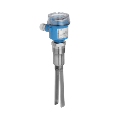
A powder level sensor is a measuring instrument that can detect the quantity and flow of powder through pipes and tanks.

In the past, the status of powder was checked manually by the human eye.

However, with a powder level sensor, the state of the fluid in tanks, pipes, and other lines can be monitored, allowing for more efficient management of work processes that use powders.

Some sensors can output an alarm if they detect a blockage or other abnormality in the powder flow.

Uses of Powder Level Sensors

Powder level sensors are used in factories in a variety of fields, such as food and chemical industries.

In addition to detecting the quantity and flow of powder, powder level sensors are useful in determining whether any abnormalities, such as clogging of tanks or piping in the manufacturing process, have occurred.

They are also used to distinguish lumps caused by powder hardening and to detect bridges in tanks.

When powder stored in a tank hardens in a pile at the bottom, it causes bridging. Bridging prevents powder from flowing freely, making it difficult to observe defects.

However, by using a powder level sensor, it is possible to observe that no flow is occurring and detect the problem as an abnormality.

Principle of Powder Level Sensors

The detection principle of powder level sensors differs depending on the specifications of the sensor part.

In the coil impedance method, a magnetic field and alternating current are applied to the electrode stones inside the sensor to detect using Ohm’s law.

Microwave sensors use the Doppler principle to measure by detecting the flow of powder generated as it naturally flows inside the piping.

In vibration sensors, a vibrating plate with an element generates vibration. An element with two-point support receives the vibrations, and the flow of powder is detected by sensing the decay of a certain amount of natural vibration.

カテゴリー
category_usa

Iron Powder Densitometer

What Is an Iron Powder Densitometer?

An iron powder densitometer is a measuring instrument that measures the metal powder contained in lubricants such as grease.

Since iron powder due to abnormal wear in lubricants can lead to reduced performance and failure, signs of failure can be detected early through periodic diagnosis.

Wear diagnosis using a powder densitometer is simple and quick. The concentration can be measured simply by passing the iron powder densitometer through the piping containing the lubricant, and the cause of failure can be noticed earlier than analysis by vibration or other external factors.

Uses of Iron Powder Densitometers

Bearings and gears are used for maintenance inspections, other maintenance, and preliminary diagnostic purposes using lubricants that are prone to wear.

The degree of wear is diagnosed from the concentration of iron powder contained in lubricants such as grease, and a management policy is determined. It is used for equipment that performs rotational operations and performs measurements on a wide range of machines, from general-purpose to high-speed rotating machines.

Principle of Iron Powder Dositometers

Iron powder densitometers detect iron powder concentration using the principle of electromagnetic induction by magnetic balance.

The coil portion that detects iron dust has an excitation coil attached to it to generate a magnetic field, and a magnetic circuit is configured so that the magnetic fields mutually disappear near the detection coil.

On the other hand, when the excitation coil is inserted into the sample, iron powder disturbs the balance of the magnetic field and generates an induced voltage, which is measured by the numerical value of the voltage to calculate the iron powder concentration.

カテゴリー
category_usa

Adhesion Promoter

What Is an Adhesion Promoter?

An adhesion promoter is an accelerator that maximizes adhesion when applied as a pretreatment for sealants and adhesives.

Instant adhesives require a long time to cure when used in large quantities, potentially leading to whitening.

Uses of Adhesion Promoters

Adhesion promoters are used in the industrial field for bonding and repairing parts.

They are used to completely cure adhesives, shorten curing time, bond porous materials, and suppress whitening when used in large quantities for filling or heaping. They also have a cleansing effect, as they remove water and oil after the dirt is removed as a pretreatment.

Since thick application can reduce adhesion, adhesion promoters should be applied thinly and evenly by spraying, using a cloth or brush, or soaking in the liquid.

Principle of Adhesion Promoters

The main ingredients of adhesion promoters have different characteristics in terms of erosiveness and curing time.

They may be cyclopentane-based, acetone-based, or alcohol-based.

Acetone is the best in terms of curing speed and preventing whitening, but it has a strong odor and erosive properties that reduce the strength of the plastic, so a slight load may cause cracking or breakage.

Cyclopentane-based products are second in both curing speed and preventing whitening, and are easier to handle because they are less aggressive and less smelly than acetone.

Alcohol-based products have the longest curing time and are less effective in preventing whitening, but they are superior in that they can be used on plastic materials because they are not affected by erosion.

カテゴリー
category_usa

Vacuum Parts Washers

What Is a Vacuum Parts Washer?

A vacuum parts washer is a device that cleans by creating a vacuum inside the washer.

Degassing and vacuuming the inside of the equipment allows the cleaning agent to reach every corner of the object, making it possible to clean areas that would otherwise be impossible to clean.

The drying process is also highly effective, and is often used in conjunction with the cleaning process. In addition, the vacuum degasses the oxygen remaining in the liquid, which increases the strength of the ultrasonic waves, making them highly effective when used in conjunction with ultrasonic cleaning.

Uses of Vacuum Parts Washers

Vacuum parts washers can safely clean objects that would normally be difficult to clean adequately or that pose a risk of fire or explosion.

Complex shapes, minuscule holes, stop holes, and bag holes can be cleaned without leaving any residue. Also, highly volatile and flammable cleaning agents used for aircraft, antennas, metal parts, etc. can be used.

Principle of Vacuum Parts Washers

Vacuum parts washers are hermetically sealed to perform the work in batches.

A vacuum is created by repeatedly depressurizing and depressurizing the inside of the equipment to remove air buildup and other obstacles, allowing the cleaning solution to penetrate the shape and details of the object to break down dirt.

In addition, the used cleaning solution is heated and evaporated in the vacuumed equipment, and only the contaminated solution is treated as waste liquid, allowing only the components of the cleaning agent to be extracted and reused.

カテゴリー
category_usa

Foreign Material Separator

What Is a Foreign Material Separator?

Foreign Material Separators

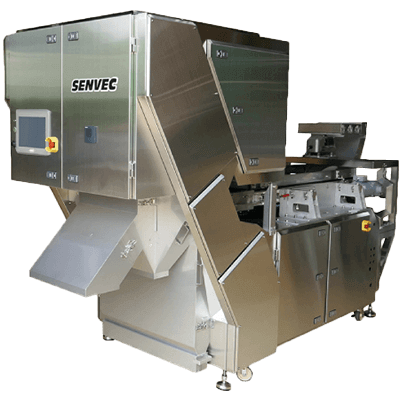
A foreign material separator is a device that removes foreign materials during powder processing to maintain high quality.

It is intended to improve work accuracy and reduce labor costs by reducing the number of personnel performing sorting, and covering oversights caused by human error.

Foreign matter removal methods include image-based identification, powder particle characteristics, and methods using magnetic force. Selecting the most effective method according to the production process and characteristics of the foreign matter ensures reliable removal.

Uses of Foreign Material Separators

Foreign material separators are used in powder processing to remove foreign matter that has been introduced during the process.

They are used in a wide range of fields, including food manufacturing, pharmaceutical manufacturing, and the chemical industry. For example, in the food field, where hygiene is important, foreign matter such as stones, sand, metals, and hair mixed in with dried food such as grains and spices are identified and removed.

Principle of Foreign Material Separators

In image-based removal, the powder on the conveyor is photographed, and a sensor is used to recognize the color and shape of the powder to remove foreign matter.

In methods that use particle characteristics, the powder is vibrated and sieved according to differences in particle size, and differences in specific gravity are analyzed to distinguish between foreign matter and powder for removal.

Magnetic removal methods use magnetic force to remove foreign matter such as metals.

カテゴリー
category_usa

Hot Air Generators

What Is a Hot Air Generator?

A hot air generator is a device such as a heater that generates hot air or warm air in a short amount of time.

They have simple structures and are easy to operate because the volume and temperature of the air can be easily adjusted.

And since nozzles can be selected based on the necessary application, the direction and range of airflow can be easily controlled, facilitating more effective usage.

Usage of Hot Air Generators

Hot air generators can be used in air conditioning systems to raise room temperatures. They can also be used for drying, heating, sterilization, melting, and other purposes.

Specific applications include drying facilities, food and pharmaceutical manufacturing facilities, steelmaking and chemical manufacturing facilities, and air conditioning facilities.

Additional examples include heat sterilization of bottles, drying of paints, and melting of chemical fibers, metals, and thermoplastic resins.

Principle of Hot Air Generators

A hot air generator consists of a temperature-controlling component and an air blower.

The heat source in the temperature controller heats air which is released through the air blower, sending hot air into the room.

There are various methods by which the temperature control component may work: combusting gas to produce a flame that generates the required heat; heating air indirectly by capturing heat from a combustion furnace; or generating heat electrically.

The electric method is superior to the combustion heating method in that it is safer and allows finer temperature control.

カテゴリー
category_usa

Low Vibration Drill

What Is a Low Vibration Drill?

A low vibration drill is a cutting tool that functions by bit rotation rather than impact as with conventional drills.

Since they do not require impact, low vibration drills significantly reduce noise caused by vibration and impact, resulting in a significantly quieter work environment.

Low vibration drills also reduce the impact on the base material, reducing chipping, scraping, and other damage, and improving the quality of the finished product.

Low vibration drills address the problems that come with conventional drills and are used in many workplaces to facilitate quiet, high-quality drilling.

Uses of Low Vibration Drills

Low vibration drills are used for work in buildings where people are present because they do not generate noise. In conventional drilling, vibration and impact from blows and noise are generated, requiring adjustments to work days and times. However, with low vibration drills, no noise is generated, making it easier to work even when people are present in the same building.

Low vibration drills are especially useful in buildings where many people gather, such as office buildings, condominiums, and hospitals, and when drilling on concrete walls and floors.

Principle of Low Vibration Drills

The principle of low vibration drills is that a bit made of diamond or other hard material at the tip of the drill rotates at high speed to perform the drilling process. This minimizes blows, impacts, and vibrations.

In addition, water or gas is sprayed during the operation to cool the frictional heat generated by the high-speed rotation of the bit. This prevents the drill from heating up and allows work to proceed efficiently.

A rubber push portion is also installed to mitigate the push force, further reducing vibration. The size of the bit can also be changed to adjust the size of the hole to be drilled.

The combination of the low vibration drill, the high-speed rotating bit, the cooling system, and the rubber push part allows for efficient drilling while suppressing vibration. The noise and vibration problems that occur with conventional drills have been solved, allowing work to be performed comfortably at a variety of sites.

Types of Low Vibration Drills

There are three main types of low vibration drills: diamond core drills, carbide core drills, and hammer drills.

1. Diamond Core Drill

Diamond core drills are drills with a pit made of diamond at the tip. They are suitable for drilling holes in hard materials. They can effectively drill holes in concrete, stone, tiles, etc. Additionally, the high-speed rotation and cooling systems enable accurate drilling with minimal vibration.

2. Carbide Core Drill

Carbide core drills have a tungsten carbide pit at the tip and are more economical than typical low vibration drills. They are suitable for machining concrete, block, and brick, and offers superior durability and cutting performance compared to diamond core drills.

3. Hammer Drill

Hammer drills are a type of drill that fall between conventional percussion drills and low vibration drills, and can be operated electrically or pneumatically. They do not have a bit at the tip; instead, drilling is achieved by striking simultaneously with rotation.

As a result, some vibration is generated, but is less than that of conventional impact-type drills. It is mainly suitable for drilling holes in soft materials such as wood, metal, and plastic.