カテゴリー
category_usa

Drill Chucks

What Is a Drill Chuck?

Drill Chucks

A drill chuck is a chuck used to secure rotating tools such as drills and screwdrivers. It is used in machine tools such as electric drills and lathes to secure the tool to the machine.

There are two types of drill chucks: keyed drill chucks and keyless drill chucks. In the case of keyed drill chucks, the cutting tool is chucked by connecting and turning a handle called a chuck key. In the case of keyless drill chucks, the cutting tool is chucked by turning a rotating sleeve on the drill chuck.

Uses of Drill Chucks

Drill chucks are used to hold tools such as drills and screwdrivers and are installed in the rotating parts of small machines like electric drills and screwdrivers, as well as relatively large processing machines such as lathes and milling machines.

Since these machine tools use different tools depending on the hole diameter and screw size for each machining procedure, it is necessary to change tools. Drill chucks improve workability by making it easy to attach, detach, and replace tools.

Principles of Drill Chucks

Drill chucks mainly consist of a jaw to hold the tool in place, a jaw guide designed to narrow the distance between the jaws as they are pushed out, and a feed screw to push the jaws out. Three jaws are arranged at 120° intervals around the circumference, and the tool is held in place at three points, ensuring that the center of the axis always coincides.

When the holder of the drill chuck is rotated manually, the jaws are pushed out by the feed screw, narrowing the width of the jaws and securing the tool. Depending on the product, the distance between the jaws generally widens from about 1 mm to 6 mm or more, allowing tools of various outside diameters to be secured.

On the other hand, since the contact area with the tool’s outer diameter is limited to the tips of the three jaws, the tool surface may be deformed depending on the tool’s strength. For precision machining of a few micrometers or accurate positioning with a slice bar, a collet chuck is used, which can clamp the tool almost around its entire outer circumference. However, when using a collet chuck, it is necessary to prepare a chuck for each tool’s outer diameter.

カテゴリー
category_usa

Tension Meters

What Is a Tension Meter?

A tension meter is a device to measure the tension of a material. Tension is the stress exerted when a material is pulled, and the value varies depending on the material and application. Tension can be measured by clamping the device between taut strings or wires.

The Device Used Differs Depending on the Range of Tension and the Shape of the Sample

The tension meter to be used depends on the range of tension to be measured. Various types of devices are available, ranging from those for large tension such as thick wires to those for low loads. Also available are devices for measuring the tension of wide samples such as film.

Uses of Tension Meters

Mainly Used With String Products Such as Wire and Rope

Tension meters are used to manage the tension of wires, strings, and ropes. Tension meters are used to check the amount of tension applied to a wire or rope in actual use and to confirm that the tension is within the allowable range.

Tension Meters Are Also Used in the Film Manufacturing Process

Tension meters are also used to measure the tension applied to film and other materials in the process. For example, if the tension applied in the film running process is too weak, the film will wave, and if the tension is too strong, the film will be stretched excessively. Therefore, measuring and controlling the tension in the process can prevent material changes.

Features of Tension Meters

There Are Portable and Line-Integrated Tension Meters

Tension meters measure the tension under which a material is pulled. For example, tension meters are used to measure tension in the manufacturing process of fibers, ropes, and wires, or to measure the tension of a running film. Tension meters can be either portable or built into the production line to record tension continuously. The former type of tension meter can easily measure tension by simply placing a sample between them. The latter device, on the other hand, can monitor changes in tension caused by process abnormalities.

Be Careful Not to Apply Excessive Load to the Tension Meter

Some tension meters are designed to measure tension while something is suspended. When using such a static tension meter, care should be taken to ensure that the tension meter is not subjected to a large load, even momentarily, such as by dropping a suspended object with great force. Also, when measuring tension and applying loads to wires and other materials used to index heavy objects, sufficient care must be taken to ensure that no breakage occurs, taking the safe usage rate into consideration.
カテゴリー
category_usa

Toolholders

What Is a Toolholder?

Toolholders

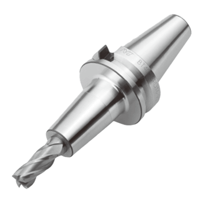
A toolholder is a connecting device, called tooling, used to connect a tool to the machine tool spindle.

Toolholders can mount and hold tools used for cutting and other purposes.

Toolholders are used to hold cutting tools. In addition to single-type toolholders, there are also toolholders that are integrated with a shank, which are used to fix a toolholder to the spindle of a machine tool.

Uses of Toolholders

Toolholders are used as peripheral equipment for tooling and to hold tools used for cutting.

There are various methods of securing toolholders, including the following:

  • Collet chucks are suitable for cutting that rotates at high speed and are used for general-purpose applications, such as drills and end mills.
  • Hydraulic chucks are suitable for high-precision machining, and hardened-fit chucks are suitable for five-axis machining and high-speed machining.
  • Milling chucks are suitable for heavy-duty machining and can be used in drilling and milling.

Principle of Toolholders

The following is an explanation of the principle of a toolholder by each type of clamping method.

In the fixing method called collet chuck, the toolholder is cut into the toolholder; the tool is passed through the toolholder, and then the tool is held by tightening the outer circumference from the outside, resulting in low runout and highly accurate mounting.

Hydraulic chucks are also known as hydro chucks.

As the name implies, it creates hydraulic pressure by applying high pressure to the oil inside the toolholder when tightening the tool. It is then deformed and secured using hydraulic pressure against the desired point.

In the case of a hard-fit chuck, the toolholder is heated to a high temperature, and the heat-induced expansion and contraction of the metal is used to tighten the tool with excellent rigidity and holding power.

Milling chucks use needle bearing forces to tighten the tool, which structurally increases the hold and rigidity of the tool.

カテゴリー
category_usa

Chip Thermistors

What Is a Chip Thermistor?

A thermistor is a semiconductor device whose resistance changes rapidly when the ambient temperature changes, and is made by mixing multiple metals.

Chip thermistors are surface-mountable thermistors on printed circuit boards.

There are two types of thermistors: NTC (negative temperature coefficient) thermistors, whose resistance decreases slowly as the temperature rises, and CTR (critical temperature resistor) thermistors, whose resistance decreases rapidly as the temperature rises. On the other hand, when the temperature rises, the resistance value rapidly increases.

Conversely, there are three types of thermistors called PTC (positive temperature coefficient) thermistors, whose resistance increases rapidly as the temperature rises.

Uses of Chip Thermistors

The resistance of NTC thermistors decreases as the temperature increases. This characteristic is used in sensors for temperature detection and in circuits for temperature control.

PTC thermistors have a temperature at which the resistance value increases as the temperature rises. This characteristic is used in temperature detection sensors, overcurrent protection circuits in place of fuses, and circuits to detect heaters and heating.

An example of actual use is in air conditioners. Both the indoor and outdoor units use thermistors to control the indoor temperature.

In cars, chip thermistors are used to measure engine temperature and outside air temperature to optimize combustion in the engine.

They are also used in home appliances such as refrigerators and coffeemakers.

Principles of Chip Thermistors

NTC thermistors are made by mixing manganese, iron, cobalt, nickel, etc. PTC thermistors are made by mixing barium titanate with ceramics or polymers with carbon black. CTR thermistors are made by mixing vanadium with additives.

Normally, when the temperature of a conductor such as a metal rises, the moving free electrons and cations in the conductor crystal collide violently with each other.

This is because the cations vibrate as the temperature rises. The collision caused by this vibration slows the speed of the free electrons, resulting in a larger resistance value.

This is why the resistance of NTC and CTR thermistors increases as the temperature rises.

On the other hand, in semiconductors, cations increase as temperature rises, and this ratio outweighs the decrease in the speed of free electron movement, resulting in a decrease in resistance.

Thus, taking advantage of the characteristics of each element, thermistors are effectively used in various places around us.

カテゴリー
category_usa

Diamond Blades

What Is a Diamond Blade?

Diamond blades are extremely hard cutting tools that use diamond particles in their blades, which are attached to engine cutters and power tools.

Dry and wet types, with or without grooving, can be selected according to the application.

If both wet and dry types are available, the wet type can be used while cooling the diamond blade, preventing it from getting too hot, and thus enabling it to perform at a higher level.

Uses of Diamond Blades

Uses of diamond blades are for cutting hard cutting materials such as roads paved with asphalt or concrete, footings supporting bridges, and buildings and other structures.

Other uses of diamond blades include grooving work, which is used to groove roads to help prevent slipping for safety purposes.

Diamond blades are also used to groove the road surface on general roads, highways, and tunnels for automobiles, as well as on airplane runways at airports.

Principle of Diamond Blades

The structure of a diamond blade consists of a base, which is made of steel or other material, and a tip, which is the part of the blade that does the cutting.

High strength is achieved by evenly adding diamond particles to the tip.

After the tip is attached to the base, the surface of the tip is polished to reveal the diamond particles inside to create the diamond blade.

Depending on the product, we use various techniques such as press-fitting diamond grains into grooves on the surface, bonding them with special fillers, or applying plating technology to adhere them to the surface to increase the retention of the grains, prevent them from flaking off or missing, and improve durability.

カテゴリー
category_usa

Die Grinders

What Is a Die Grinder?

A die grinder is a cutting tool that can perform grinding and polishing. It is powered by compressed air and is also a pneumatic tool.

They are used in combination with an air compressor.

Die grinders are characterized by their small size and light weight, and their ability to work at high speeds.

Angled and straight types are available, and some have a downward-pointing tip while others are pen-shaped.

Some products are designed to reduce the coldness characteristic of die grinders by using resin for the grip and body parts.

Uses of Die Grinders

In general, most die grinders are small, lightweight, and easy to work with.

They are used to perform cutting and polishing operations.

Specifically, die grinders are used to grind dies, etc., remove burrs and beads, correct spot welds, chamfer cut surfaces, etc., and perform surface grinding.

They can also be used to finish and prepare holes drilled with a drill and perform fine-tuning.

Principle of Die Grinders

Die grinders can be classified into the category of air grinders among grinders.

Air grinders are powered by compressed air.

Die grinder can be powered by connecting it to an air compressor using piping and an air hose.

To perform cutting operations, a cutting tool is attached to the tip of the Die grinder.

Depending on the application, the shape of the grinding wheel attached to the tip can be changed, and by rotating the grinding wheel at the tip, cutting, polishing, or grinding can be performed on the object.

The angle type has a downward-facing cutting tool at the tip, so the grinder can be held by hand for vertical grinding.

In the straight type, the tip of the cutting tool is pen-shaped in the same direction as the handheld part, so you can hold the grinder in your hand and grind in a straight line like a pen.

カテゴリー
category_usa

Tungsten Electrodes

What Is a Tungsten Electrode?

A tungsten electrode is an electrode used for welding.

It is made of tungsten and processed into a cylindrical shape. They are sold in diameters ranging from 1.0 to 4.0 mm and lengths of about 150 mm.

Uses of Tungsten Electrodes

Tungsten electrodes are used for welding. Therefore, construction sites and processing plants are the main places where they are used.

Specific applications are as follows:

  • For repairing boilers
  • Maintenance and modification of motorcycles and automobiles
  • Shipbuilding in shipyards
  • For piping repair in chemical plants

Basically, it is used for welding of metal base materials. Among manufacturing industries, this component is often used in heavy industries.

Principle of Tungsten Electrodes

Tungsten electrodes are rods made of tungsten. Tungsten is a metal with an atomic number of 74 and is represented by the element symbol W. It is characterized by relatively high resistance and a high melting point among metals.

Tungsten electrodes are used as electrodes for TIG welding, taking advantage of their high melting point. TIG welding stands for “tungsten inert gas” welding and is a welding process using a tungsten electrode and inert gas. A high voltage is applied between the base metal to be welded and the tungsten electrode to generate an arc discharge.

The heat generated by the arc discharge melts the base metal for welding. During this process, inert gases such as argon and helium are sprayed to prevent oxidation and deterioration of the metal. The high melting point of the tungsten electrode allows welding without mixing with the base metal. The tip of the tungsten electrode is machined into a conical shape at the time of use. The shape of the arc discharge can be changed by this cutting angle.

When the tip of the tungsten electrode is sharply angled, the arc spreads over the entire area. A large area of the base material can be melted shallowly. When the angle is obtuse, the arc concentrates on a single point at the tip. This enables deep melting of a single point of the base material.

Types of Tungsten Electrodes

There are four types of tungsten electrodes. The four types are thorium oxide, cerium oxide, lanthanaum oxide, and pure tungsten electrode. Each has different characteristics, so it is important to use the appropriate one depending on the application.

1. Tungsten Electrode With Thorium Oxide

This is a tungsten electrode containing 1~2% thorium oxide. It is characterized by its strength against abrasion and startability, which are superior to those of pure tungsten electrodes. However, the tip of the electrode is easily deformed when used with AC current, and it may melt and scatter during welding. Therefore, it is suitable for applications welding with DC current.

2. Tungsten Electrode With Cerium Oxide

This is a tungsten electrode containing 1~2% cerium oxide. The tip of the electrode does not melt and scatter even with AC current, and it has higher resistance to abrasion and startability than the electrode containing thorium oxide. It is suitable for AC welding of aluminum and aluminum alloys.

3. Tungsten Electrode With Lanthanum Oxide

Tungsten electrodes containing 1~2% lanthanum oxide have the highest resistance to abrasion and startability among the four types of electrodes, and can be used continuously for a long time while maintaining arc stability. It is suitable for automatic welding and is used in applications such as robot welding.

4. Pure Tungsten Electrode

This is a tungsten electrode composed only of pure tungsten and has the weakest resistance to abrasion and startability among the four types of electrodes. While the tip wears out quickly, once it becomes round, it does not deform any further, so it is characterized by its resistance to splattering during welding. Therefore, it is used for AC welding applications where electrode wear is high.

Other Information on Tungsten Electrodes

Distinguishing Colors of Tungsten Electrodes

Identification colors of tungsten electrodes are specified for each of the aforementioned types. The identification color is a color to be painted on the rod end for easy recognition at the time of sale, and is specified according to the standards.

The following are the identification colors of each electrode:

  • Yellow: 1% thoriated tungsten electrode
  • Red: 2% tungsten electrode with thorium
  • Peach: 1% cerium-in-tungsten electrode
  • Gray: 2% cerium-in-tungsten electrode
  • Black: 1% tungsten electrode with lanthanum
  • Yellow Green: 2% tungsten electrode with lanthanum
  • Green: Pure tungsten electrode
カテゴリー
category_usa

Tapping Machinery

What Is Tapping Machinery?

Tapping machinery, also known as a tapper, is a machine used for threading screws into metals, including steel, stainless steel, and aluminum plates.

Standard tapping machinery processes screws one at a time. However, there are machines available that can process multiple screws simultaneously or be programmed to automatically process screws.

Uses of Tapping Machinery

Tapping machinery is employed to create threaded holes when working with screws in various metals such as steel, stainless steel, and aluminum.

It finds applications in a wide range of products, including hexagonal, square, flange, round nuts, bent taps, straight taps, flange nuts, bag nuts, and aluminum nuts.

Principles of Tapping Machinery

Tapping machinery utilizes a special drill-like tool called a tap to thread holes while cutting through the material.

The tapping process requires the tap and the workpiece to be lubricated with cutting oil during operation.

While it is possible to automate this entire process, some tapping machinery includes a mechanism for automatic application of cutting oil to enhance efficiency.

A digital counter is often integrated to prevent oversight by the operator, allowing them to monitor the machine’s progress as they work.

These machines are capable of handling a wide range of taps, from standard high taps to special carbide taps.

Servo control through a sequencer governs overall speed, torque, and motion, enabling precise lead (pitch) feed tapping.

Shaft rotation and feed rates can be easily and accurately adjusted without the need for part replacements.

Some tapping machinery features a system designed to minimize tap runout during tapping operations.

They are engineered to accommodate both bent and straight taps within a single unit.

Torque trends over the tap’s entire lifespan can be graphed to aid in analysis, control, and quality improvement.

Online connectivity allows for remote monitoring and storage of various tapping data.

Tapping data can be analyzed, configured, automatically determined during operation, and adjusted for efficient operation.

カテゴリー
category_usa

Tact Switches

What Is a Tact Switch?

Tact Switches

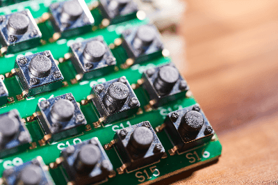
Tact switches, also called tactile switches, are a type of switch for low currents. The switch is energized only when it is pressed, and de-energized when it is released. The tact switch also has a clicking sensation when the switch is pressed, providing the operator with sensory feedback as to whether or not the switch has been pressed. Various types of switches exist, depending on their shape, size, and mounting method on a circuit board, and are used for different purposes.

Uses of Tact Switches

Tact switches are widely used in electronic devices that require human input operations, such as printers, washing machines, and other electrical appliances, as well as various control panels. Ultra-small tact switches are ideal for electronic devices that require space-saving mounting, such as smartphones. Tact switches are also available in sealed types, which are waterproof and dustproof, and are used in control panels used in bathrooms and in electronic equipment that is expected to be used outdoors.

Principle of Tact Switches

Tact switches are mainly composed of the following five parts. By changing the shape and materials of the parts, a soft or firm clicking sensation can be achieved to suit various applications.

  1. Cover parts
  2. Push plate
  3. Film
  4. Movable contacts
  5. Base part with fixed contacts

The above parts are stacked in order on top of the base parts in 5.

When a finger is pressed on a tact switch with this component configuration, the push plate is pushed in, which pushes the movable contact, and the movable contact reverses and makes contact with the fixed contact, causing current to flow (state of switch ON).

Since the movable contact has spring-like characteristics, when the finger is released, the movable contact reverses and returns to its original state, the movable and fixed contacts separate, and the switch is turned OFF.

The movable contacts, which have spring-like characteristics, are designed to physically repeat the reversal. However, due to the ingenuity of the materials and shape, they generally require high durability to withstand 100,000 to 10 million cycles of use.

カテゴリー
category_usa

Throttle Valves

What Is a Throttle Valve?

Throttle Valves

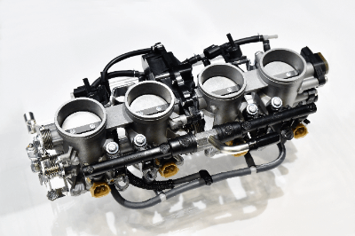
A throttle valve is a valve installed in the passage of a fluid. Throttle valves adjust the flow of fluid by changing the cross-sectional area of the passage. They are primarily used to regulate the amount of air intake into the engines of automobiles, motorcycles, aircraft, and agricultural machinery. In automobiles, the degree of opening and closing of the throttle valve is adjusted by the accelerator pedal. In the past, throttle valves were controlled using a wire in a system known as mechanical throttle, but in recent years, electronic throttle systems have become more common, where the degree of valve opening and closing is electronically controlled.

Uses of Throttle Valves

Throttle valves are mainly used in automobiles, motorcycles, aircraft, and agricultural machinery. This section will focus on their use in automobiles.

In automobiles, throttle valves are attached to the throttle body in the air intake passage (intake pipe) and regulate the amount of air intake into the engine to control power output. Throttle valves can be single or multiple, with each installed in a single throttle body.

Throttle valve adjustment is typically done using the accelerator pedal. In the past, the valve was opened and closed using a wire mechanism, but in recent years, electronic systems have taken over. The engine’s Electronic Control Unit (ECU) adjusts the valve based on driving conditions and the position of the accelerator pedal.

Principles of Throttle Valves

Let’s explain the principle of throttle valves using an automobile as an example. Throttle valves are attached to the throttle body in the intake air passage (intake pipe). When the accelerator pedal is pressed, the degree of valve opening/closing is adjusted to control the amount of intake air entering the engine. There are two main types of throttle valves: butterfly valves and slide valves, each with its own working principle.

  • Butterfly Valve: This type of valve is circular and installed in the intake air passage. It rotates vertically in response to the position of the accelerator pedal to control the degree of valve opening and closing.
  • Slide Valve: Slide valves are flat, plate-shaped valves installed in the intake air passage. They open and close based on the degree of acceleration, thus controlling the degree of valve opening and closing.
    Throttle valves can be operated mechanically or electronically.
  • Mechanical Throttle: In this system, the throttle pedal and throttle valve are connected by a wire. The valve opens and closes according to the pressure applied to the accelerator pedal.
  • Electronic Throttle: In this system, the pressure applied to the accelerator pedal is converted into an electrical signal, which is then transmitted to the engine ECU. The degree of valve opening/closing is adjusted considering various factors, such as driving conditions, fuel consumption, and exhaust emissions.

Throttle Valve Failure

Throttle valves play a role in reintroducing and reusing a small amount of dust and exhaust gases that cannot be prevented by the air cleaner, delivering clean air into the engine (EGR), and managing a re-combustion system (PCV) for gases that leak slightly from the gap between the cylinder and piston due to incomplete combustion (blow-by gas). The combination of these three elements can lead to a gradual buildup of carbon and sludge.

This accumulation of debris can hinder normal operation, resulting in reduced fuel economy, unstable idling, and reduced power output. In severe cases, it can even prevent the engine from starting.

In the case of electronic throttle systems, which are prevalent in modern cars, the computer can adapt to some extent to a dirty throttle valve. However, periodic cleaning is still necessary to maintain the system’s performance in good condition.

It’s worth noting that diesel engines do not incorporate throttle valves in their design. In diesel engines, the throttle pedal controls the amount of fuel injected into the compressed air rather than the opening and closing of valves, making throttle valves unnecessary.

Sticking Throttle Valves

When carbon buildup prevents normal operation, it results in a condition known as “sticking” throttle valves, which can lead to engine malfunctions.

One method for cleaning a sticking valve involves disassembling it until it is exposed and then applying a special cleaner directly onto the valve. You can scrub it with a brush or wipe off the dirt with a rag.

To disassemble the valve, remove the duct connecting the valve to the air cleaner so that the valve is visible, and clean it in this condition. For thorough cleaning, remove the valve from the engine and work on it separately.

Various cleaners can be used, including engine conditioner, carburetor cleaner, and dedicated throttle valve cleaner.

After cleaning, it is important to reset the computer, which has adapted to the dirty conditions, to restore the original performance of the system.