カテゴリー
category_usa

3D Printers

What Is a 3D Printer?
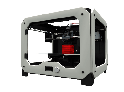
3D PrintersA 3D printer is a device that produces three-dimensional objects by layering printed cross sections based on 3D data.

3D printers can be produced using a variety of methods, including the FDM (fused deposition modeling) method, SLA (stereo lithography) method, SLS (selective laser sintering) method, inkjet method, inkjet powder laminate method, and inkjet powder laminate method. 

For home use, two types of 3D printers are often used: “thermal melting lithography method” and “optical lithography method.”

Applications, Principles, and Advantages of Each Type of 3D Printer

1. Fused Deposition Modeling Method (FDM)

Uses
Production of figures, models, etc.

Principle
Thermoplastic resin is ejected through a thin nozzle of around 0.5mm to print.

Advantages

  • Inexpensive main unit
  • Printing is possible at low cost due to inexpensive materials
  • Mainstream as 3D printer for general use

Disadvantages

  1. Requires support materials
  2. Appearance of the modeled object deteriorates due to stacking marks generated during printing

Printable Materials
PLA resin, ABS resin, etc.
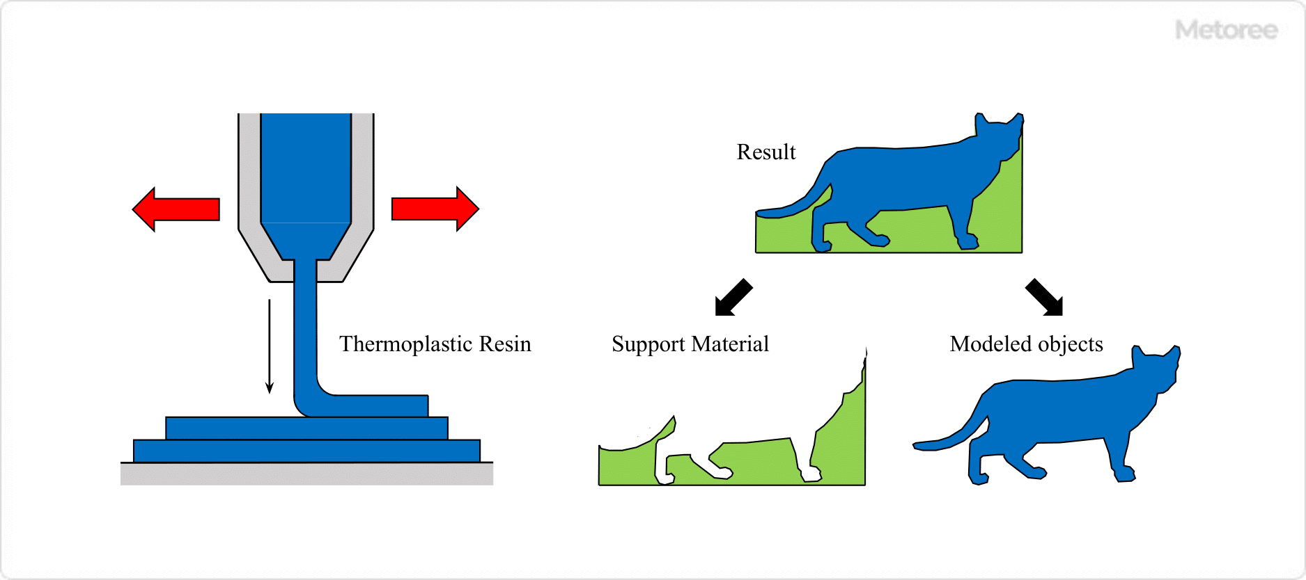
3D-Printers_3Dプリンター-1

Figure1. Thermal Melting Lamination Method

2. Stereolithography Method (SLA) 

Uses
SLAs are used for the creation of mock-ups, stage props, etc.

Principle
Printing is performed by exposing a light-curing liquid resin to light to cure it.

Advantages
Easy to process after modeling, and transparent printed materials can be created.

Disadvantages

  • Printed materials are vulnerable to sunlight
  • Time-consuming post-processing of printed materials

Printable Materials
Epoxy resins, acrylic resins, etc.
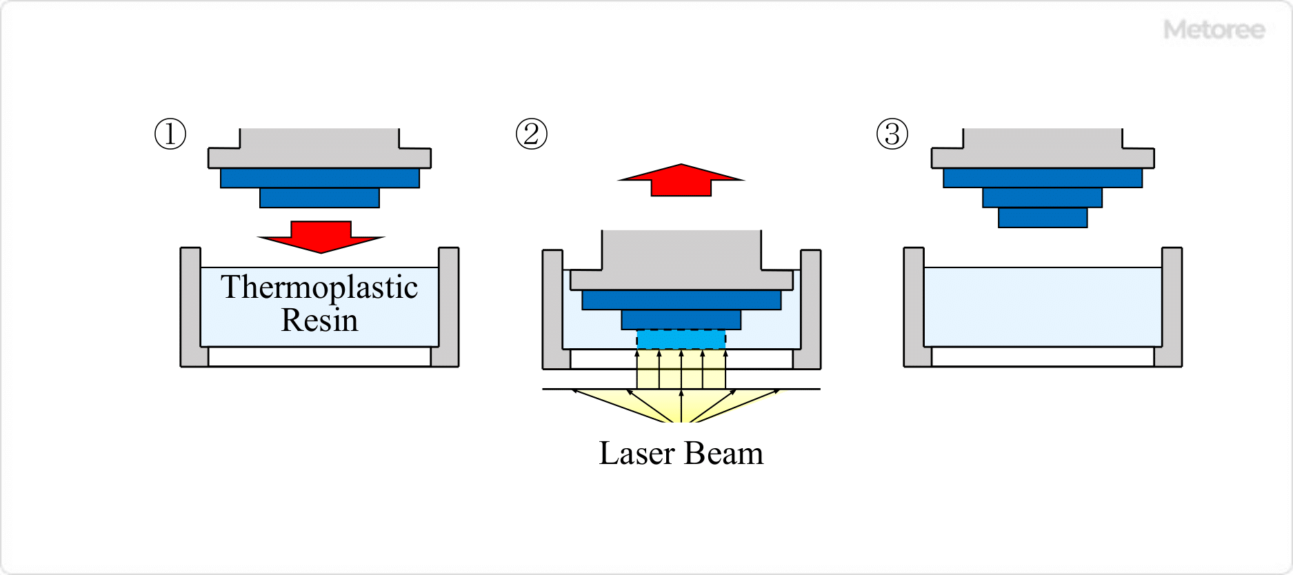
3D-Printers_3Dプリンター-2

Figure2. Optical fabrication method

3. Selective Laser Sintering Method (SLS)

Uses
Parts for industrial equipment and medical implants

Principle
Printing is performed by repeating selective heating and sintering of powdered materials one layer at a time.

Advantages
Large-scale, strong structures can be printed without the need for support materials

Disadvantages

  • Equipment, including the printer itself, is expensive
  • Printed materials have rough surfaces.

Printable Materials
Nylon, metal materials such as titanium, etc.
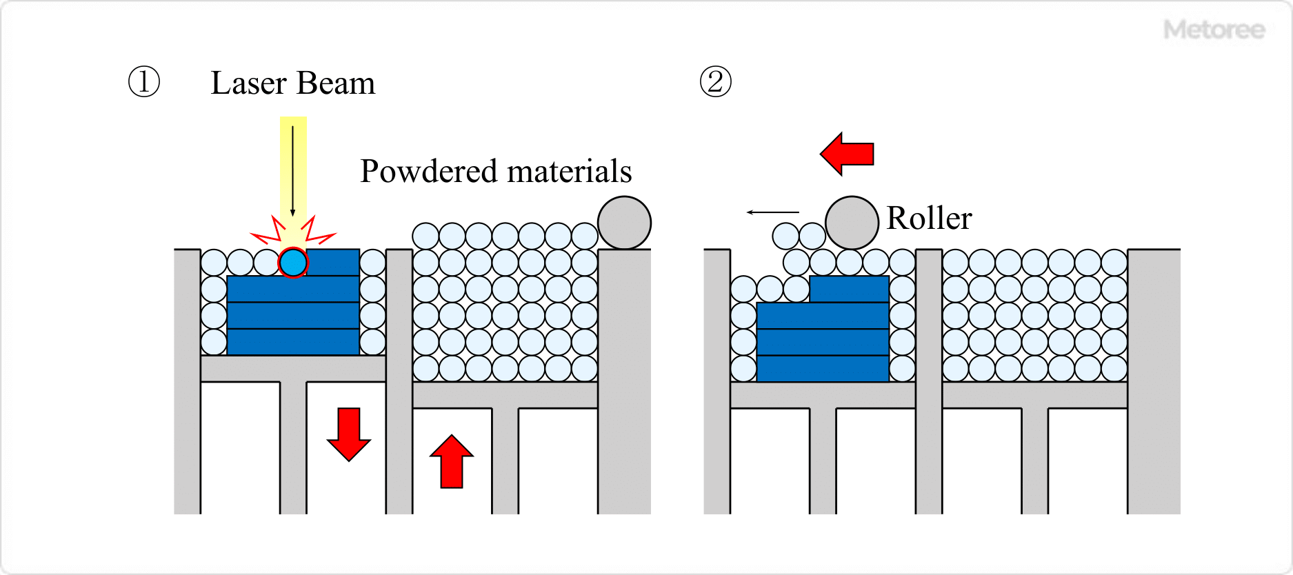
3D-Printers_3Dプリンター-3

Figure3. Powder Sintering Additive Manufacturing Method

4. Inkjet Method

Uses
Manufacture of medical parts and small-lot products

Principle
UV-curable material is placed on a two-dimensional surface as if it were printed by an ordinary printer and then cured by UV irradiation to produce a print.

Advantages
Easy installation and high-resolution printing

Disadvantages
Printed materials are brittle and vulnerable to sunlight.

Printable Materials
Epoxy resin, acrylic resin, ABS resin, etc.
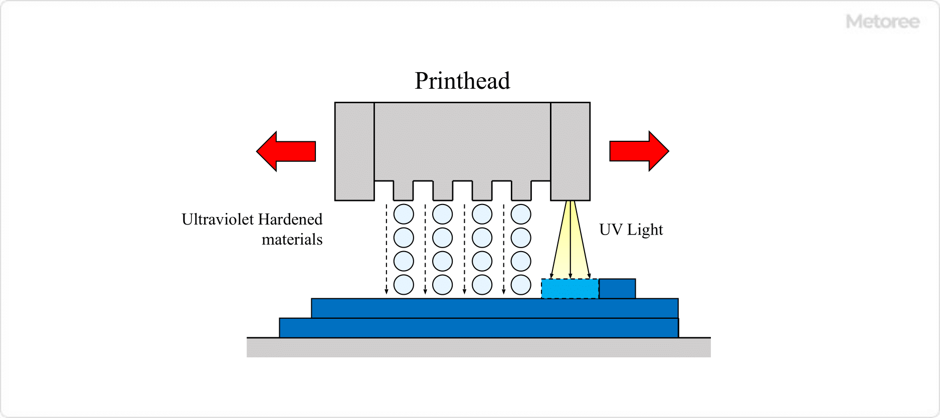
3D-Printers_3Dプリンター-4.

Figure4. Inkjet method

5. Inkjet Powder Lamination Method

Uses
Medical parts, small lot product manufacturing

Principle
Printing is performed by placing an adhesive on plaster and allowing it to cure. Color structures can be created by using colorants.

Advantages
Easy installation and high-resolution printing

Disadvantages
Printed materials have low strength

Printable Materials
Plaster, resin, metal, sand, etc.
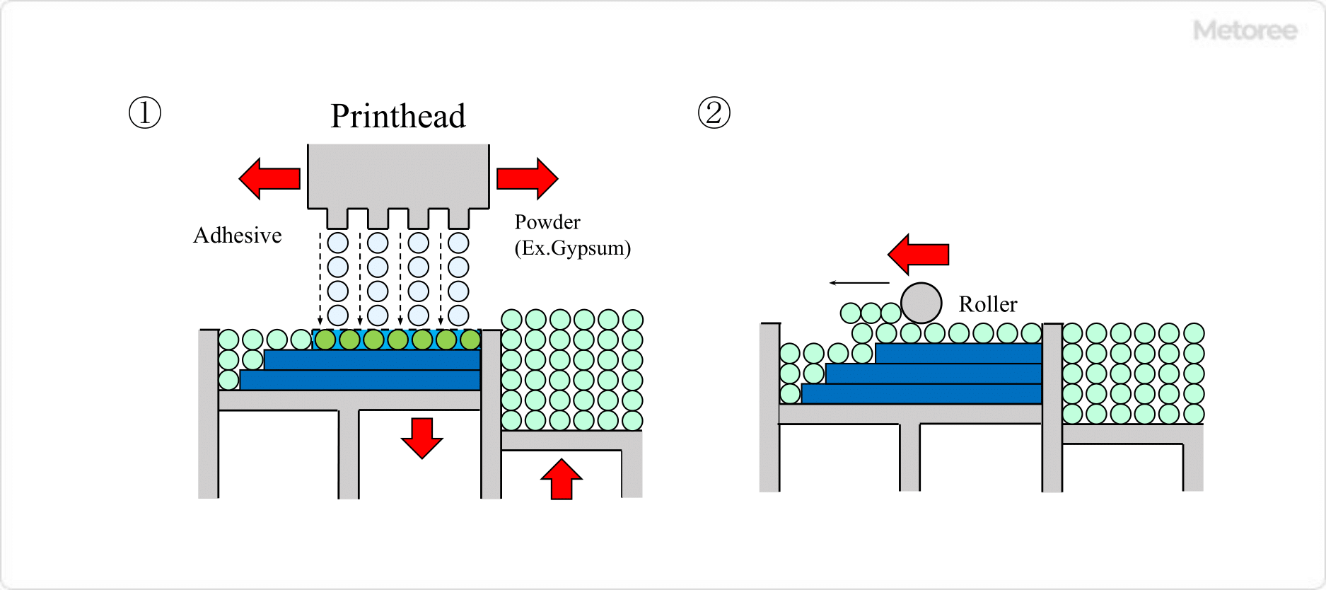
3D-Printers_3Dプリンター-5.

Figure 5. Inkjet powder lamination method

How to Use a 3D printer

3D printers can be used to layer the designed structure by melting the resin.

This section explains what you need to prepare and the actual procedure.

What You Need to Prepare

  • Personal computer
  • 3D printer
  • 3D CAD software for designing three-dimensional CAD drawings
  • Slicing software
    Slicing software has the ability to convert 3D data into tool path data.
  • Filament
    Filament is a material to be laminated; its type varies depending on the 3D printer’s lamination method, but PLA resin and ABS resin are most commonly used by beginning users.

Steps to Layering a Structure on a 3D Printer

    • To laminate a structure, create 3D data by using 3D CAD software.
    • Convert the 3D data to STL format so that the 3D printer can read the data.
    • Convert STL data to tool path data.
    • Activate the 3D printer.
    • Remove secondary materials that are welded to the structure as support materials.
    • Surface treatment of burrs, etc. for a smooth finish.
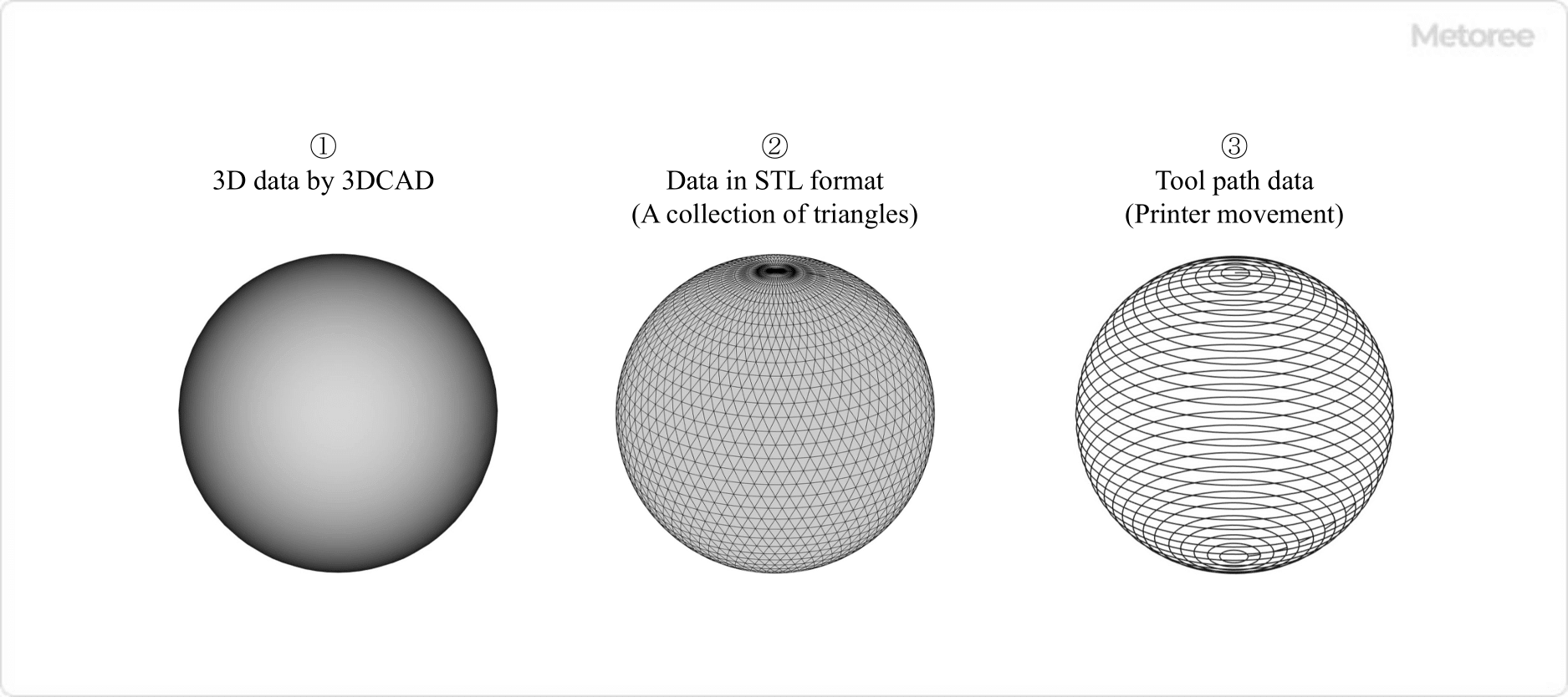
3D-Printers_3Dプリンター-6

Figure 6. Conversion from 3DCAD data to tool path data

Filament Materials That Can Be Handled

3D printers are limited in the materials they can handle, depending on the type of equipment and the melting method of the material.

For example, a 3D printer that can handle resins can handle both general soft and hard resins. Some types of 3D printers can handle a wide range of materials.

Here, we will focus on resin and metal as filament materials that can be handled.

Resin Filament

The most commonly used types of resin filaments for both beginners and advanced users are PLA and ABS resins.
Other resin materials include nylon, plaster, rubber, and epoxy-based materials.

  • PLA Resin
    This resin is synthesized from recycled materials consisting of polylactic acid, which is mainly made from corn, etc.
  • ABS Resin
    A synthetic resin composed of acrylonitrile, butadiene, and styrene.

Metal Filament

Types of metal filaments include stainless steel, brass, titanium, platinum, silver, and gold.

Other special materials include filaments containing bronze as a powder.
カテゴリー
category_usa

Media Converters

What Is a Media Converter?

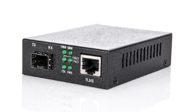
Media ConvertersA media converter is a device for connecting a metal cable, which transmits information using electrical signals, and an optical fiber, which transmits information using light as the medium.

A media converter is a device for mutually converting signals in different media, but the media used here are limited to electrical and optical signals. In other words, a media converter is a device that converts electrical signals into optical signals and optical signals into electrical signals, and is also called an optical media converter or MC.

Uses of Media Converters

Media converters are used to connect metal cables, which transmit information using electrical signals, and optical fibers, which transmit information using light as the medium. Metal cables that transmit electrical signals are susceptible to electromagnetic noise as well as signal attenuation as the transmission distance increases. Therefore, the transmission distance is limited to about 100 m.

On the other hand, transmission of optical signals by optical fiber is not affected by electromagnetic noise and is less susceptible to signal attenuation, making it ideal for transmission over long distances. However, since the signal medium is different between metal cables, which transmit signals based on voltage changes, and optical fiber, which transmits signals based on light flashes, the signals must be converted to each other in order to connect the two.

Therefore, a network line that takes advantage of the strengths of each cable is constructed by intervening media converters and mutually converting the two types of signals.

Principle of Media Converters

Typically, a pair of media converters is installed at both ends of an optical fiber connecting two networks built with metal cables. The first media converter converts the electrical signals of the metal cable to optical signals of the optical fiber. The electrical signal input to the media converter is transmitted to a light emitting device such as a laser diode, and output to the fiber optic cable as an optical signal modulated in response to the signal.

The second media converter converts the sent optical signal into a change in voltage by means of a light-receiving element and restores it to the original electrical signal. This mechanism enables reliable signal transmission over long distances using an optical fiber between the two networks.

Media converters can also be classified into the following two types according to the way packet signals are processed.

1. Repeater Type

This type is characterized by the fact that the transmission speed of the electrical signal side is equal to that of the optical signal side. When the communication speeds are the same, conversion can be performed without delay. In other words, when a media converter receives a packet of electrical signals, it immediately converts it into optical signals and outputs them regardless of their contents.

There is no signal delay time, making this mechanism suitable for applications where transmission speed is critical and signal delays are not tolerated. In addition, any packet can be used regardless of the communication protocol, as it passes through without modification. Even if an error packet exists, it is not discarded. This is effective when monitoring equipment to grasp information on equipment trouble and utilize it for countermeasures.

2. Bridge Type

In the bridge type, the packet signal sent from the transmitting side is once received by the media converter on the transmitting side in a buffer circuit. It then converts them to optical signals and transmits them to the media converter on the receiving side.

Therefore, this type can handle cases where the communication speeds of electrical and optical signals are different, and is also called a switch type. Another feature of this type is that communication can be continued without any problems, even if the communication speed between the connected devices is changed for some reason.

Compared to the repeater type, the transmission delay is larger due to the buffer circuit, and the larger the packet length to be transmitted, the more noticeable the delay becomes. On the other hand, the bridge type can determine and remove error packets as soon as the signal is received in the buffer circuit.

Other Information on Media Converters

1. Support for Single/Double-Core Optical Fiber Cables

Generally, a dual-core type is used for optical fiber communications. This is a communication method that uses a dedicated optical fiber core for each of the transmitting and receiving sides, which is usually connected using a cable with two cores in one set. Since light always travels in a fixed direction, the structure of the media converter is simple.

On the other hand, there is a single-core type that uses a single optical fiber core to pass light in both directions, i.e., bidirectional communication. This type of media converter is often used in environments where space is limited, such as when many optical fibers need to be passed through. In single-core bidirectional communications, opposing media converters use light sources with different wavelengths, so the light receiving element must also be sensitive to the wavelength of the other side.

In other words, single-core media converters must be equipped with light sources of different transmit wavelengths from each other, and the light-receiving part must be a combination of light-receiving elements with light-receiving elements that match the transmit wavelength of the other side.

カテゴリー
category_usa

Reed Switches

What Is a Reed Switch?

Reed SwitchesA reed switch is a switch with two magnetizable reeds in a glass tube that turns electrical contacts on and off.
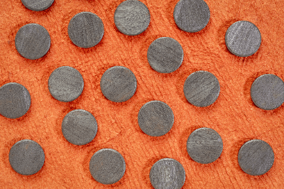
When open, a typical reed switch opens with a small gap between the reed contact edges; when an external magnetic field (e.g., a magnet) is applied to the two reed contact edges, the reed contact edges attract each other and close, closing the circuit.

Uses of Reed Switches

Reed switches are used in the following applications:

Reed switches are turned on and off by magnets, so they can be used for non-contact detection. Reed switches are mainly used for non-contact detection of equipment status.

Principle of Reed Switches

The components of a reed switch include a glass tube, a reed strip, a magnet, and a contact.

  1. Two magnetic reed strips, which are easily magnetized, are enclosed in a glass tube with a certain overlap and spacing.
  2. When a magnet or other object is brought close, the contact edges associated with the two lead strips are attracted to each other, closing the circuit.
  3. When the magnet is moved away, the spring force of the leads opens the contacts.
  4. The contacts are sealed in a glass tube with nitrogen to insulate them from the external environment.

Since the contacts are not contaminated, reed switches have very low contact resistance. The contacts are mainly made of metal and have a short operating distance, giving them an open/close life of up to several hundred million cycles.

Other Information About Reed Switches

1. Failure of Reed Switches

Reed switches are components with moving parts. Therefore, there is no possibility of failure. The main possible failures include contact failure, contact sticking, and unexpected malfunction.

Contact Failure
Factors that can cause contact failure include deterioration of the magnet over time and carbonization due to chemical changes on the contact surfaces. Since carbonization of the contact surface is unlikely to occur in a nitrogen atmosphere, the glass capillary may be cracked.

Contact Sticking
Contacts may stick due to deterioration of the spring or welding of the contacts due to overcurrent. Deterioration of the spring is mainly due to aging, while welding of the contacts may be caused by an abnormality on the electric circuit side, so caution is required.

Unexpected Malfunction
Unexpected malfunctions may be caused by a random combination of the above two causes. In this case, it is very difficult to identify the cause.

Reed switches are components that are relatively unlikely to fail. To deal with failures, it is essential to design circuits with redundancy and prevent malfunctions. In addition, since reed switches are inexpensive, they are sometimes designed from the beginning on the assumption that they will be replaced at regular intervals.

2. Points to Note About Reed Switches

Reed switches sense the proximity of a magnet. However, because the operating range over which the switch operates is not uniform, there is a risk of chattering. Equipment design must take chattering into consideration.

On the other hand, the distance between the contacts of reed switches is very small and the contact pressure is very slight. Because they are precision components, they must be used strictly within their rated current values. In addition, even when used within the rated current value, care should be taken not to apply strong shocks.

In addition, using reed switches under a strong magnetic field may cause malfunctions. In such an environment, a magnetic shield should be provided to block external magnetic forces.

カテゴリー
category_usa

COM Express

What Is a COM Express?

COM Express

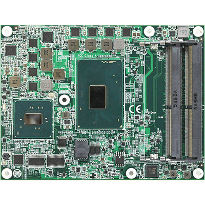
A COM Express (Computer On Module) is a COM standard defined by PICMG.

It refers to the adoption of technologies such as PCI Express and Serial ATA to existing COM. A COM Express board typically includes a CPU, memory, bus interface, and more, and it is connected to a carrier board and a card carriage. It is a device that can fully function as a computer.

The adoption of COM Express in products allows for speedy product development, simplified development, and reduced development costs. It also improves the future potential of the product, as modules compatible with the COM Express standard will be available in the market in the future.

Uses for COM Express

COM Express is used in a wide range of applications and industries due to its flexibility and scalability. Below are some key use cases:

1. Industrial Computers

In industrial applications such as factory automation, industrial control, and robotics, COM Express provides robustness and reliability in computer systems. Customizable features and expandability are essential to meet the specific requirements these applications.

2. Medical Equipment

For applications in the medical field, such as diagnostic and therapeutic equipment, COM Express offers reliability and high performance. Fast data processing and real-time responsiveness are critical elements in the diagnosis and treatment of patients.

3. Aviation and Defense Industry

COM Express modules are widely used in applications requiring high performance and reliability in the aviation and defense industry, such as aircraft navigation systems and military communications equipment. In these industries where robustness and long-term support are required, COM Express provides the ideal solution.

4. Telecommunication Networks

COM Express provides high-speed data transfer and high reliability to meet the requirements of telecommunication infrastructures. In devices such as network switches and routers, COM Express provides a reliable, high-performance platform.

Principle of COM Express

COM Express comprises a board with interfaces that can be connected to the CPU, memory, bus, USB, and other components. It also includes a card carriage insert and a connection to a carrier board. It can be mounted on a carrier board, and new modules can be inserted into the carrier board to expand the functionality of the product.

PCI Express, the technology used in COM Express, is a standard for expansion slots that can exchange electrical signals at high speed, allowing the insertion of graphics cards and other devices. Serial ATA, another technology used in COM Express, is a standard for connecting hard disks and other devices to COM Express, allowing them to exchange data at high speed.

Types of COM Express

COM Express offers a variety of form factors and pin assignments, depending on the application and requirements. The most typical of these are four form factors and three pin assignments.

1. Classification by Form Factor

  • COM Express Mini
    The smallest model, designed for applications requiring an extremely small footprint. It is typically found in mobile devices and small devices.
  • COM Express Compact
    Slightly larger than the COM Express Mini, this model offers more computing power and connectivity options. Its compact design makes it suitable for a wide variety of applications.
  • COM Express Basic
    The most common form factor, offering a wide range of I/O and high-performance computing options. They are widely used in industrial equipment, networking equipment, and other high-performance systems.
  • COM Express Extended
    The largest form factor, offering the most high-performance computing capability and the broadest range of I/O options. It is designed for the most demanding applications.

2. Classification by Pinout

  • Type 6
    The most common pinout, providing common I/O and display interfaces. It is typically used in applications where graphics processing power is critical.
  • Type 7
    Optimized for server applications and provides 10 Gigabit Ethernet (10GbE) and additional PCI Express (PCIe) lanes instead of a display interface.
  • Type 10
    This pinout is dedicated to COM Express Mini and prioritizes miniaturization and ruggedness. It is typically found in mobile and low power applications.

Thanks to these types, COM Express can adapt to a wide variety of requirements and applications and meet the needs of any industry. This is one of the reasons why COM Express is widely adopted in the industry.

カテゴリー
category_usa

Power Module

What Is a Power Module?

A power module is a product that integrates power-related circuits into a single module package by combining multiple power semiconductors.

By integrating the necessary functions in an IC (semiconductor integrated circuit) and optimizing the low-power design, power modules are used in a wide range of fields, including industrial equipment used in factories, large white goods, automobiles, railroads, and new energy sources. This technology is used in a wide range of fields, including industrial equipment used in factories, large white goods, automobiles, railways, and new energy.

The market for power modules is still growing rapidly.

Uses of Power Modules

The most familiar application of power modules is the inverters installed in air conditioners, refrigerators, washing machines, and so on. These inverters can control the speed of motors by converting their frequency.

By freely changing the number of motor revolutions, it is possible to reduce wasteful movement and contribute to energy conservation. In contrast, air conditioners without inverters can only turn the motor on and off, which leads to the repetition of extreme movements such as running and stopping the air conditioner, resulting in wasteful power consumption.

Inverters are used to control the speed of motors and are also used in electric vehicles such as HEVs and EVs. It is important that the vehicle’s drive not only turns on and off but also detects and controls the spinning of the tires.

Without this control, the vehicle will slip. In snowy regions, power must be applied to the tires safely and efficiently, and very fine control of motor power is important and indispensable, especially in EVs and HEVs.

Principle of Power Modules

A power module consists of multiple power transistors optimized for its required power supply application, together with a bias drive circuit, and modularized together with peripheral components to improve withstand voltage and switching speed and efficiency during power operation. In addition, the package and substrate are characterized by their heat dissipation and other features that make them easy to use.

Among the power semiconductors widely used in power modules, power transistors have the widest range of applications. The situation is such that technological development is being actively pursued mainly by semiconductor and materials manufacturers. Among power transistors, there are several semiconductor devices listed below.

1. Bipolar Transistor

Bipolar transistors have a simple structure and can handle large amounts of power. However, they have the disadvantages of slow switching speed and high power consumption. In recent years they are no longer the mainstay of power module applications.

2. Power MOSFET

Power MOSFETs (FETs: Field Effect Transistors) have the advantage of the fastest switching speeds and low power consumption. However, they also have the disadvantage of not being able to handle large amounts of power.

3. IGBT

Developed in the 1980s, Insulated Gate Bipolar Transistors (IGBTs) can handle large amounts of power. Compared to MOSFETs, IGBTs are capable of switching that is not too much inferior to MOSFETs. The circuit configuration is a combination of a MOSFET and a BJT (Bipolar Junction Transistor).

Other Information on Power Modules

1. Trends in Next-Generation Power Modules

SiC-MOSFETs have recently been attracting attention as devices for next-generation power modules, because SiC substrates have higher bandgap energy and higher breakdown voltage than Si substrates.

IGBTs can handle high power even with Si substrates, but their bipolar structure makes it difficult to increase the switching speed. SiC-MOSFETs, which are high-power devices with fast switching speed, are currently being considered for next-generation power modules.

The weakness of SiC substrates in mass production has been overcome by the emergence of substrate manufacturers capable of handling 6-inch substrates, which is a result of technological innovation.

2. Power Modules in EVs

The voltage of lithium-ion batteries in EVs is related to the charging time, so we are aiming to shorten the charging time by high-speed charging. To improve the efficiency of the power train, which is equivalent to the engine of an EV, we are working to reduce the current 400V level. In order to improve the efficiency of the powertrain, which corresponds to the engine of an EV, further increase in voltage, from the current 400V to, for example, 800V, is required.

In order to handle high voltage and high controllability of in-vehicle motors, it is important to switch the AC current generated by the inverter circuit at high speed, and power devices and power modules are used here.

カテゴリー
category_usa

Curve Tracers

What Is a Curve Tracer?

A curve tracer is a device that displays the relationship between the voltage applied to a semiconductor device and the current flowing through it.

It is called a curve tracer because it traces a graph (curve) of the voltage-current characteristic and displays it on a display. In semiconductor devices, the relationship between the applied voltage and the flowing current is non-linear and not proportional, like a resistor.

Therefore, measuring the voltage vs. current characteristics of semiconductors and electronic devices requires procedures such as changing the voltage, measuring the current value, and plotting the results on a sheet of paper. With a curve tracer, however, the voltage-current characteristic can be directly displayed on a display.

Uses of Curve Tracers

Curve tracers are used to measure the characteristics of semiconductor devices during development, to inspect devices in manufacturing departments, and to verify the operation of circuits using semiconductors. The main measurement targets are semiconductor devices such as diodes, bipolar transistors, and FETs.

In semiconductors, the voltage applied to the target device is gradually varied and the current flowing at that time is measured. On the other hand, the display of the curve tracer shows the voltage value on the X-axis and the current value on the Y-axis, thus depicting the relationship between the voltage and the current value as a graph.

Optional power supplies are available for high voltage application and high current flow, and the equipment is ready to accommodate a variety of devices.

Principle of Curve Tracers

1. Measurement of Diodes

If the measurement object is a diode, connect a power supply for driving the device between the anode and cathode, set the maximum and minimum applied voltage values Vmax and Vmin, and the power supply will automatically sweep the voltage between them at a frequency of 50Hz to 60Hz. It also measures the current value flowing through the diode at this time.

The horizontal sweep circuit of the CRT uses the voltage of the power supply for driving the semiconductor device as the input signal, while the vertical sweep circuit uses the current flowing through the diode as the input signal, so that the current characteristic (V-I characteristic) against the applied voltage is drawn on the CRT.

2. Transistor Measurement

For bipolar transistor/FET measurements, a current/voltage source using a step generator is connected to the base/gate electrodes. The device drive power supply is connected between the emitter/source and collector/drain, and the maximum and minimum values of the applied voltage, Vmax and Vmin, are set.

For Bipolar Transistors
If the base current is varied stepwise with a step generator and the voltage between emitter and collector and collector current at that time is displayed on the CRT, the static characteristic curve of the transistor is drawn.

In the Case of FET
When the gate voltage is varied stepwise with a step generator, a static characteristic curve of a FET is drawn, showing the relationship between the voltage between source and drain and the drain current.

Curve tracers are designed based on the assumption that a CRT is used for the display. However, since CRTs are rarely produced anymore, the conventional type of curve tracer has disappeared.

Instead, a curve tracer that draws characteristic curves on a display by importing voltage-current characteristic data into a PC is now commercially available.

Structure of a Curve Tracer

A curve tracer consists of a power supply for driving devices, a step generator for controlling transistor base current and FET gate voltage, a CRT and its horizontal sweep and vertical sweep circuits, etc.

Other Information on Curve Tracer

Semiconductor Parameter Analyzer

Curve tracer is a very effective measuring instrument for understanding the basic characteristics of semiconductors, and was a basic measuring instrument utilized in all processes from research and development to product inspection, especially by device manufacturers. They are also used in user acceptance testing of semiconductor devices, and although several Japanese manufacturers used to produce them, all but a few have now withdrawn from the market.

On the other hand, curve tracers, which were developed for solar panel evaluation, are now being sold. In addition, semiconductor parameter analyzers have replaced curve tracers.

These are equipped with multiple voltage and current sources, and the voltage and current are controlled by a controller (PC) to measure the characteristics of semiconductors.

カテゴリー
category_usa

Backplane

What Is a Backplane?

A backplane is a circuit board used in electronic equipment such as computers and telecommunications equipment to connect boards and cards.

It is typically mounted on the back of a device to transmit power and signals to inserted cards and modules. A backplane also consists of brackets for securing boards, sockets for supplying power, and connectors for transmitting signals.

Backplanes are essential to the performance of electronic devices. They support the board, reduce the effects of board vibration and heat, and improve reliability.

Uses of Backplanes

1. Servers and Network Equipment

Backplanes are used in hardware such as servers, network switches, and routers. These devices require many components to process data in parallel at high speed. The backplane efficiently transfers data between these components to maximize system performance.

2. Data Storage System

Backplanes are commonly used in data storage systems to process and store large amounts of data at high speed. These include RAID arrays and storage area networks (SANs).

3. Industrial Computers

Backplanes are also common in computer systems used in manufacturing, energy, transportation, and other industries. Ruggedness and reliability are important in these systems, and backplanes are used to meet these requirements.

4. Test Equipment

Test equipment is used to measure the performance and quality of electronic equipment. Test equipment uses backplanes to connect multiple test cards to accommodate a wide variety of measurement items and conditions.

Principle of Backplanes

To understand the basic workings of a backplane, it is important to understand how it connects hardware components and transfers data.

1. Component Connections

A backplane essentially consists of one or more printed circuit boards. These boards are equipped with slots or ports for connecting the various components of a computer system.

These slots essentially correspond to a specific type of component (e.g., CPU, RAM, hard drive, etc.). Components are physically connected to these slots and communicate with other components through the backplane.

2. Data Transfer

One of the primary functions of a backplane is to allow data transfer between components. This is done through electronic circuits located on the board. Each component uses these circuits to send and receive data.

Depending on the backplane design and component type, data can be transferred in parallel (multiple bits are transferred simultaneously) or in serial (one bit at a time).

3. Plug and Play

Some backplanes offer plug-and-play capability to facilitate the addition or replacement of components. This means that a new component can simply be physically plugged into a slot and the system will automatically recognize its presence and enable it to operate properly.

Together, backplanes allow the components of a system to work together efficiently and share data. Backplanes are critical to the performance and scalability of a computer system.

Types of Backplanes

Backplanes come in a variety of standards and forms.

1. Classification by Standard

Backplane standards include PICMG, ISA, PCI, among others. PICMG is a standard developed by the PCI Industrial Computer Manufacturers Group that supports PCI and PCI Express. ISA (Industry Standard Architecture) is a standard which was adopted for early IBM PCs and other products.

PCI (Peripheral Component Interconnect) is the standard which enables high-speed data transfer.
These standards are sometimes, but not always, compatible. The backplane and the cards or boards to be connected must support the same standard.

2. Classification by Form

There are two forms of backplanes: active and passive. Active backplanes contain chips that buffer signals between slots and can accommodate complex systems.

Passive backplanes do not have any features that drive the circuitry, but have arbitration circuitry on the card or board side. Active backplanes are more likely to fail than passive backplanes.

カテゴリー
category_usa

Ferrite Magnet

What Is a Ferrite Magnet?

Ferrite Magnets

Ferrite magnets are made by mixing iron oxide with cobalt, nickel, and manganese. The molecular formula is represented as MFe2O4 (M = Mn, Fe, Co, Ni, Cu, Mg, Zn, Cd, etc.).

The composite metal M is dominated by divalent cations, and Fe3O4, where M = Fe, is black and is a well-known raw material called magnetite. Other compounds exist where the compound metal M is 1, 3, or even tetravalent cations, called ferrite.

The manufacturing process involves pressing powdered ferrite and baking it at high temperatures. It is also a type of ceramic. It can be synthesized from iron oxide Fe2O4 and is therefore inexpensive.

The characteristics of ferrite magnets are that they can be easily formed into any shape and are easy to process and that they are chemically stable and resistant to corrosion by rust and chemicals.

Applications of Ferrite Magnets

Applications of ferrite magnets can be divided into two types: hard ferrite and soft ferrite.

1. Hard Ferrite

Hard ferrite magnets are ferrite magnets that become permanent magnets once they are attached to a strong magnet (by applying a strong magnetic field). U-shaped magnets are the most common type of magnet we see in our daily lives.

U-shaped magnets are typical examples. They are also used in small motors, speakers, headphones, and cassette tapes. 

2. Soft Ferrite

Soft ferrite is a ferrite magnet that becomes a magnet when in contact with a magnetic field and ceases to be a magnet when removed from the field. It is often used as a magnetic core and is suitable for transformers and coils.

Examples of easy-to-understand applications are used in radios, televisions, game consoles, automobiles, personal computers, microwave ovens, vacuum cleaners, and refrigerators.

Principle of Ferrite Magnets

The magnetic properties of ferrite magnets differ between hard ferrites and soft ferrites. First, let us explain the magnetic properties. Figure 1 shows the spin state of each magnetic property.

1. Magnetic Properties

  • Ferromagnetic: A material whose magnetic moment (a vector quantity that expresses the strength and direction of a magnet) is aligned without the application of a magnetic field is called a ferromagnetic material.
  • Ferrimagnet: A ferrimagnetic material is one in which the magnetic moments of neighboring atoms are opposite in direction but different in magnitude so that the material as a whole is magnetized. All ferrite magnets are ferrimagnetic.
  • Paramagnetic: When there is no magnetic field, the magnetic moments are oriented in various directions, but when a magnetic field is applied, the magnetic moments become aligned.

The types and characteristics of each type of ferrite magnet are shown in Figure 2. Saturation magnetization is the maximum magnetization at which the magnetization of a material does not increase even if the magnetic field is increased. Curie temperature is the temperature at which the magnet changes from ferromagnetic to paramagnetic.

2. Hard Ferrite

Hard ferrite is a ferromagnetic material and a permanent magnet. Hard ferrites can be further classified into isotropic and anisotropic magnets according to the orientation of the magnetic poles of their molecules.

  • Isotropic Magnets: The magnetic moment is oriented in various directions. Since the orientation of the magnetism is not uniform, it can be magnetized from any direction, but the magnetic force is weak.
  • Anisotropic Magnets: The orientation of the magnetic moment of the molecules is aligned, providing directionality but a strong magnetic force. It is produced by aligning the magnetic poles of each ferrite molecule by applying a magnetic field during the hardening process.

3. Soft Ferrite

Soft ferrite is magnetic only while an external magnetic field is applied. Although the magnetic field is smaller than that of hard ferrite, it has excellent magnetic properties over a wide frequency range.

For example, a spinel-type crystal structure has a high magnetic permeability (the degree to which a material is magnetized) over a wide range of frequencies. The garnet type has the property that single crystals are not easily broken in the microwave frequency range.

Comparison With Alnico Magnets

Alnico magnets are manufactured by adding aluminum (Al), nickel (Ni), cobalt (Co), and other additive elements to iron and using casting methods or powder sintering.

Alnico magnets are characterized by their extremely high Curie temperature (the temperature at which they cease to be permanent magnets) of 860°C, allowing them to be used in high-temperature environments. Alnico magnets can recover their original magnetic force when returned to room temperature at temperatures ranging from room temperature to 400℃. Those manufactured by casting also have excellent mechanical strength.

Applications for Alnico magnets include electric motors, sensors, speaker units, and magnetic pickups for electric guitars.

Differences From Ferrite Magnets

Ferrite magnets are primarily composed of iron oxide, while Alnico magnets are composed primarily of iron with aluminum, nickel, and cobalt added. The retention of magnetic force in an Alnico magnet is small and easily demagnetized.

There is a limitation that they must have a long shape due to the need for a long distance between the poles. Also, the supply of the raw material, cobalt, is unstable and expensive, so ferrite magnets are less expensive.

Comparison With Samarium Cobalt Magnets

Samarium cobalt magnets are rare earth magnets composed of samarium (Sm) and cobalt (Co). They are divided into SmCo5 (1-5 series) and Sm2Co17 (2-17 series) according to their composition ratio, with the 1-5 series, which contains less samarium, being widely used today.

Samarium cobalt magnets are characterized by a high Curie temperature of approximately 800°C at maximum. Because of its excellent corrosion resistance, it can be used as is without surface treatment, and its shape is highly selectable. Magnetic properties are higher than those of ferrite magnets and second only to those of neodymium magnets.

Differences From Ferrite Magnets

Because they can be used in environments up to about 350°C, they are used in space-saving, high-temperature environments where higher magnetic force than ferrite magnets is required. On the other hand, it has the disadvantage of low strength, which makes it prone to cracking and chipping. The raw materials samarium and cobalt are both rare, making them very expensive compared to ferrite magnets.

Comparison With Neodymium Magnets

A neodymium magnet is a magnet composed mainly of neodymium (Nd), iron (Fe), and boron (B). Neodymium magnets are characterized by their easy oxidation and high thermal dependence.

Because they oxidize easily, their surfaces are nickel-plated before use. They are usually used at temperatures below 80°C. Because of its relatively high strength, it is also resistant to cracking and chipping.

Differences From Ferrite Magnets

Compared to ferrite magnets, magnetic properties are extremely high, with about four times the magnetic holding power and 10 times the maximum energy product. It is more expensive than ferrite magnets, but less expensive than samarium cobalt magnets.

カテゴリー
category_usa

Pulse Generator

What Is a Pulse Generator?

Pulse GeneratorsA pulse generator is a device that generates rapidly occurring and converging electrical signals called pulses.

Pulse generators can adjust pulse frequency, pulse width, voltage level, and timing delay. Pulse generators include pulse delay generators, burst generators, and gate generators.

Uses of Pulse Generators

Pulse generators are used in a wide range of applications, from industrial to consumer products.

Familiar products include medical pacemakers and automobile engines. These applications take advantage of the pulse generator’s ability to input pulses of electrical signals at high speed.
Other applications include strobe control and observation of high-speed moving objects.

Another common use is as a power source for semiconductor lasers (LDs). A semiconductor laser emits light when electricity exceeding a threshold value is input. A pulse generator is necessary when the laser light is pulsed. Pulsed lasers are mainly used for laser processing and signal transmission.

Principle of a Pulse Generators

To generate pulses with a pulse generator, a commercial alternating current must be converted to a direct current by a transistor or other means. In addition, the DC current is converted to a higher voltage by means of a capacitor or other storage device.

The most common method for generating pulse current from high-voltage current is to use a concentrated constant circuit. In a concentrated constant circuit, a gap switch is used. The gap switch allows the charge to accumulate in the capacitor until a threshold value is reached and then releases the charge when the threshold value is reached. The repetition of this process generates a pulse.

Types of Pulse Generators

There are several types of pulse generators depending on their application and function. Therefore, it is necessary to select the appropriate one for each application. The three main types of pulse generators used are pulse delay generators, burst generators, and gate generators.

1. Pulse Delay Generator

A time delay can be applied to the pulse oscillation. Also, the timing of the light-receiving device can be matched to the laser oscillation.

2. Burst Generator

The burst trigger is used as the criterion for judging whether the gate is valid or invalid. Therefore, regardless of whether the reference signal is input or not, no pulse is output unless the burst trigger is input to the generator. It is often used for the evaluation of wireless terminals.

3. Gate Generator

A pulse generator whose output pulses can be controlled by a gate trigger. Pulses are output when a reference signal is input during the gate trigger input. In the case of burst triggering, the gate generator will accept all subsequent reference signals that are input once, but will not accept a reference signal if the gate trigger is disabled.

Other Information on Pulse Generators

Price of Pulse Generators

Pulse generators are expensive and are a fixed asset when purchased. Besides, their use is often temporary, unless they are built internally for processing machines.

Therefore, they are often procured through rental or lease.
Prices range widely from 300 to 6000 USD (monthly) depending on performance. Some high-performance pulse generators made by major U.K. manufacturers can cost 7500 to
40,000 USD when purchased.

カテゴリー
category_usa

Controller

What Is a Controller?

A controller is a device used to adjust a machine’s output automatically.

Often sold under indicating regulators or temperature regulators, many devices marketed as controllers can also control parameters other than temperature.

Physical parameters such as temperature, humidity, pressure, and flow rate are input from sensors to indicate a value. Feedback is applied to match this with the target value you set. Most products have a display for monitoring both the current value of the parameter being adjusted and the set value.

If the display uses an analog pointer, it is termed an analog controller. If it features a 7-segment display, it is called a digital controller. Currently, digital controllers are the most common type. In analog controllers, the display may omit the current value.

Uses of Controllers

Controllers are widely used in applications ranging from industrial equipment to household appliances, as exemplified below:

Controllers are utilized to maintain constant parameters and may be used alongside computers to log monitored data.

Principle of Controllers

A controller consists of a sensor, a processing/monitoring part, and an output section. The sensor inputs physical quantities such as temperature (using a thermometer) or humidity (using a hygrometer), among others.

The processing and monitoring section adjusts the output while monitoring the value. A built-in comparator or similar device compares the measured value to the target value to determine the output, which is then sent to the output section. Various feedback control methods are employed.

1. ON/OFF Operation

Output is activated when the measured value is below the target value and turned off when above. This repeated operation maintains the measured value near the target.

2. Proportional Operation (P Operation)

This operation adjusts the control output proportionally to the deviation from the target value, enabling smoother regulation than ON/OFF operation, though with relatively large fluctuations near the target. Integral operations, etc., adjust the stabilization offset slightly off the target value.

3. Integral Operation (I Operation)

Based on the time integral of the difference between the target and measured values, this operation is often used to eliminate offset appearing in proportional operation, typically in conjunction with P operation.

4. Differential Operation (D Operation)

This operation outputs based on the rate of change (derivative) of the measured value. PID operation, combining P, I, and D operations, integrates the benefits of each method.

How to Select a Controller

Controllers are selected based on mounting size, input specifications, output specifications, communication methods, and other factors.

1. Mounting Size

Consider the panel size where the controller will be mounted. Select a product that fits the available installation space, opting for smaller sizes if mounting multiple controllers in a row.

2. Input Specifications

Choose based on the controlled physical quantity’s input signals and number of input points. For temperature inputs, resistance thermometers or thermocouples (PT100Ω, K, R, B types) are common, with 4-20 mA or 1-5 V inputs for other parameters.

3. Output Specifications

Output specifications match the signal transmitted to the output device. Analog control typically uses 4-20 mA or 1-5 V outputs, while ON-OFF control employs contact or transistor outputs, selected based on the output device’s specifications.

4. Communication Method

For interfacing with computers, communication methods facilitate transmitting measured or output values to a computer or altering target values from a computer. Ethernet communication has become mainstream, succeeding older serial communication standards like RS422 or RS485.