カテゴリー
category_usa

Hydraulic Valves

What Is a Hydraulic Valve?
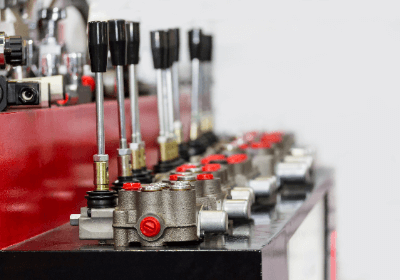
Hydraulic Valves

A hydraulic valve is a device used to control the flow of fluid in a hydraulic system.

They are used in machines and equipment to transmit and control power. Hydraulic valves control the operation of a system by adjusting the pressure, flow, and direction of fluid according to specific conditions.

These devices are widely used in a variety of industries, including automotive braking systems, construction machinery, and factory production lines. These valves stabilize machine operation by providing efficient and accurate control.

Applications of Hydraulic Valves

The main applications of hydraulic valves are as follows:

1. Construction Machinery

In construction machinery such as bulldozers, excavators, and cranes, hydraulic valves are used to control drive systems and braking. This provides precise control of machine operation and improves safety and efficiency.

2. Agricultural Machinery

In agricultural machinery such as tractors and combines, hydraulic valves are used to control the operation of steering, lifting, and traction devices.

3. Factory Machinery

In factory production lines and machinery, hydraulic valves are used to control movement. This ensures proper regulation of machine movement and pressure to make the production process more efficient.

4. Industrial Machinery

In industrial machinery such as presses, injection molding machines, and robotic arms, hydraulic valves are used for precise motion control.

5. Aircraft and Ships

In aircraft and ships, hydraulic valves are used to control flight control systems, landing gear, hydraulic doors, etc.

6. Vehicles

Hydraulic valves are incorporated in the braking systems of cars and trucks. This ensures that the proper braking force is applied and that the driver can safely control the vehicle.

7. Pressure Control Systems

Hydraulic valves are sometimes used to control pressure. Examples include automotive suspension systems and hydroforming processes.

Principle of Hydraulic Valves

Hydraulic valves use hydraulic pressure to drive valves. Hydraulic drives use the incompressibility of oil to drive a machine or system. When oil is subjected to pressure, the force generated by the oil is transmitted to the machine or actuator to control its motion or force.

When oil is pressurized, the pressure is transmitted evenly throughout the liquid, effectively transferring the force received by the oil to the actuator. The principle of hydraulic drive is also based on Pascal’s principle. Pascal’s principle states that when a fluid is in a closed container, the pressure on the fluid is evenly distributed, and that a small force can be applied to produce a large force by using the pressure of the fluid.

In other words, hydraulic drives can generate large forces and torques by taking advantage of the incompressibility of fluids. This allows them to lift heavy loads and perform tasks that require high torque. Hydraulic valves are therefore particularly suited for controlling highly viscous fluids that require high forces and torques.

Types of Hydraulic Valves

The main types of hydraulic valves are as follows:

1. Switching Valve

A switching valve switches the fluid between the input and output ports. By supplying fluid to different ports, the operation of the system can be switched.

2. Pressure Control Valve

Pressure control valves are used to control the pressure in a system. They help to set a specific pressure value, prevent the system from overloading, and ensure the required operation.

3. Flow Control Valve

Flow control valves are used to control fluid flow. They can ensure a specific flow rate and regulate the speed and operating stability of the system.

4. Directional Control Valve

Directional valves are used to control the direction of fluid flow. They help to change the operating direction of cylinders and actuators.

5. Quasi-Safety Valve

Quasi-Safety Valves are used to prevent abnormal pressure build-up in a system and open automatically when a specific pressure is exceeded.
カテゴリー
category_usa

Vibration Sensors

What Is a Vibration Sensor?

Vibration Sensors

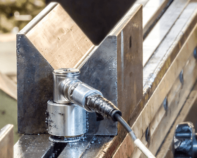
Vibration Sensors are sensing elements used to measure the vibration state of a machine or object.

Vibration Sensors are necessary to understand and monitor the vibration state of a machine. There are three indices that represent the vibration of an object: acceleration, velocity, and displacement. Vibration Sensors measure these physical quantities and convert them into electrical quantities such as voltage and current.

In general, Vibration Sensors are available in two configurations: contact and non-contact. Depending on the physical quantity being measured (acceleration, velocity, displacement) and the conditions of the object, these two types of Vibration Sensors must be used in different ways. In addition, the magnitude and frequency range of the object being measured, as well as the measurement environment, must be taken into consideration when selecting a detailed Vibration Sensor to improve measurement accuracy.

Applications of Vibration Sensors

Vibration Sensors are used in production facilities and research and development. In production facilities, Vibration Sensors are useful for preventive maintenance to detect equipment failures and damage at an early stage. The use of sensors can prevent the occurrence of huge repair costs and loss of production efficiency due to breakdowns and damage.

In recent years, small Vibration Sensors have been used in production facilities, mostly for the purpose of machine diagnostics and predictive maintenance using IoT technology. An example of the use of Vibration Sensors in the field of research and development is the measurement of vibrations in product testing and durability testing.

Vibration Sensors are also used to evaluate passenger comfort, particularly in the automotive industry. Other applications in the field of industrial equipment range from electrical equipment and automobiles to production robots.

Principle of Vibration Sensors

As mentioned above, there are two types of Vibration Sensor configurations: contact and non-contact. Contact Vibration Sensors are used to measure acceleration, while non-contact Vibration Sensors are used to measure velocity and displacement.

This section introduces the principle of each type of Vibration Sensor suitable for various vibration (acceleration, velocity, and displacement) measurements. 

1. Contact Type: Acceleration-Sensing Piezoelectric Sensors

Piezoelectric sensors utilize the piezoelectric effect that occurs in piezoelectric materials. The piezoelectric effect is a phenomenon in which a piezoelectric material (piezoelectric element), such as a single crystal of quartz, generates an electric charge on its surface when subjected to a force. The piezoelectric effect produces an electrical signal corresponding to the acceleration.

2. Non-Contact: Laser-Doppler Sensor with Velocity Detection

Laser-Doppler sensors are sensors that utilize the Doppler effect. A laser beam is emitted from the Vibration Sensor to a vibrating object, and the frequency change of the laser beam reflected from the vibrating object is converted into a voltage as a change in velocity.

3. Non-Contact Type: Displacement-Detecting Capacitive Sensor

Capacitive sensors are sensors based on the principle of measuring the capacitance between the sensor and the object to be measured and calculating the distance. When the distance between the sensor and the object to be measured changes, the capacitance value changes, thereby measuring the displacement of Vibration Sensor.

Other Information on Vibration Sensors

1. Detecting Elements of Vibration Sensors

The detection element of mechanical vibration is the temporal change in the magnitude of a quantity representing the motion or displacement of a mechanical system. In many cases, the vibration alternates between a state that is greater than or less than the average or reference value. In general, this vibration is composed of three elements: amplitude, frequency, and phase.

In particular, vibration that repeats at regular intervals is called harmonic vibration and consists of a single frequency. In such cases, displacement, velocity, and acceleration are as follows. By differentiating the displacement, the velocity can be derived, and by differentiating the velocity, the acceleration can be derived.

  • Displacement d = Dsin (ωt + Φ)
  • Velocity v = Vcos (ωt + Φ)
  • Acceleration a = – Asin

D: single amplitude, ω: each velocity ω=2πf, f: frequency f=1/T, T: period (seconds), Φ: initial phase.

The types of Vibration Sensors used to detect this harmonic vibration include Acceleration Sensors (piezoelectric type), Velocity Sensors (electrokinetic type), and Non-contact Displacement Sensors (eddy current type). Among these, the piezoelectric type acceleration sensor in particular is characterized by its ability to cover a wide frequency range. 

2. Usage of Vibration Sensors

As an example, we will explain how to use a piezoelectric Vibration Sensor, which is used for vibration monitoring. Piezoelectric Vibration Sensors utilize the piezoelectric effect, and when an external force is applied, they generate and output an electric charge proportional to that force. Piezoelectric Vibration Sensors with charge output are particularly advantageous for miniaturization.

It is important to fix the sensor firmly with stud bolts to ensure it closely adheres to the non-measured object. If the sensor is not firmly attached, it may exhibit distinctive filter characteristics with peculiar attenuation patterns in the frequency response, thus making accurate measurements impossible. Other methods include using adhesives or magnets to fix the sensor.

Frequency analysis is widely used to analyze data detected by Vibration Sensors. Frequency analysis is a method of examining the frequency components and intensity of the measured waveform, and can provide an indicator to determine whether the vibration of an object is in normal operating condition or not.

カテゴリー
category_usa

Photoelectric Sensors

  • What Is a Photoelectric Sensor?

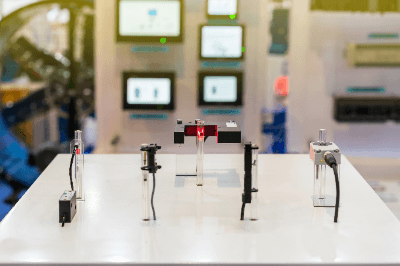
Photoelectric SensorsA Photoelectric Sensor is a sensor that detects light.
The sensors use the properties of light to detect the surface shape and condition of the object being measured, as well as its constituent materials.

They are suitable for pre-shipment inspection and nondestructive testing equipment because they can detect surface shape and constituent substances without contact.

They are characterized by their ability to measure long distances, short response time, and high resolution. Detection methods include transmissive, retro-reflective, and diffuse-reflective types.

Uses of Photoelectric Sensors

Photoelectric sensors are used in a wide range of applications from consumer products to industrial equipment. Examples of applications are as follows:

  • Inspection in production plants for food, consumer products, etc.
  • Automatic doors and ticket gates of buildings and condominiums
  • Distance measurement sensors for mobile transportation equipment such as trains and automobiles
  • Laboratory equipment such as thickness measuring instruments and non-destructive testing equipment

Principle of Photoelectric Sensors

Photoelectric sensors consist of a projector with a built-in light emitting element, a receiver with a built-in light receiving element, an amplifier or other amplifying device, and an output terminal.

They can be classified into transmission, retro-reflection, and diffuse-reflection types according to the measurement method.

1. Transmission Type

In the transmission type, a measurement target is placed between the projector and receiver, and light emitted from the projector is intercepted by the measurement target to detect the target. As long as the object is opaque, measurement is possible regardless of its color or constituent substances. 

2. Retro-Reflection Type

In the retro-reflection type, a projector and a receiver are combined into a single unit, and the object to be measured is placed between the projector and the receiver and a reflector. The reflector can be installed in a narrow space, allowing measurement in a limited space. 

3. Diffuse-Reflection Type

The diffuse reflection type detects light emitted from the transmitter and receiver by reflecting it back at the object to be measured. It is characterized by its ability to distinguish colors.

Other Information on Photoelectric Sensors

1. Difference Between Photoelectric and Laser Sensors

Photoelectric and Laser Sensors are divided by the type of light source used. Photoelectric sensors generally use LED light sources, while laser sensors use laser light.

Laser light is more directional than LED light, and the diffusion of light emitted from the projector is smaller. Therefore, even small objects can be detected. Also, the light can be projected over long distances without attenuation due to its high energy.

When LED light is emitted from a floodlight, it cannot detect small objects due to diffusion and wrap-around effects. It is also not suitable for detection over long distances because its energy is not high. Also, if neighboring photoelectric sensors are installed nearby, false detection may occur due to diffuse light.

Photoelectric sensors are therefore used when less accuracy is required and are less expensive. Laser sensors are used for applications that require high accuracy, such as long-distance detection and small object detection, and are relatively expensive.

2. How to Use Photoelectric Sensors

Photoelectric sensors are used in many facilities because they are inexpensive and easy to handle, but if used incorrectly, they can cause problems.

One of the most common problems with photoelectric sensors is mutual interference between adjacent sensors. Mutual interference occurs when light emitted from the light emitter of one sensor enters the light receiver of the other sensor.

The LED light source of a photoelectric sensor diffuses the light after irradiation, and the longer the projection distance, the greater the diffusion width.

To prevent mutual interference, it is effective to separate the installation distance, to install the light emitters and receivers alternately, and to install anti-interference filters or light shields. Generally, the recommended installation distance is 1.5 to 2 times the operating distance. If the installation distance needs to be closer, interference prevention filters should be considered. Anti-interference filters are sold by various manufacturers according to the sensors.

カテゴリー
category_usa

Power Inductors

What Is a Power Inductor?

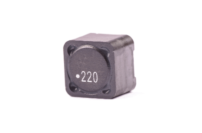
Power InductorsA power inductor is an element of a coil used in a power circuit among inductors.
They are also called power chokes. There are three basic types of construction: windings formed by lamination technology, windings on a bar-shaped core, and windings on a drum-shaped core.

Inductors, including power inductors, have a property that allows DC current to pass through, but prevents AC current from passing through. This property is used to eliminate high-frequency noise in circuits for voltage conversion.

Impedance is a measure of the resistance to the passage of alternating current, and the following formula for the impedance of an inductor easily explains this property.

Impedance of inductor [Ω]ZL=jωL 
(L: inductance [H] ω: angular frequency [rad/s])

Uses of Power Inductors

Power inductors are used in a wide range of fields such as home appliances, communication equipment, and transportation equipment to stabilize the voltage supply of power circuits. Examples include smartphones and automobiles.

Controlling the voltage of a DC power supply is very important for any electronic device. The reason is that electronic devices have a range of supply voltages that can guarantee normal operation, and the ability to supply the proper voltage to each component affects stable circuit operation and the life of the equipment.

A DC-DC converter is a circuit that converts voltage, and the supply of stable voltage depends on the performance of the Power Inductor. There are two types of converter circuits: a step-down type that lowers the voltage, and a step-up type that raises the voltage. Both types contain switching elements, diodes, and power inductors as components.

Principle of Power Inductor

When an alternating current flows through an inductor, electromagnetic induction generates an induced electromotive force proportional to the time rate of change of the current.

 Induced electromotive force [V]e = -L* (dI/dt)
(L: inductance [H] I: current [A] t: time [sec])

Since the direction of the induced electromotive force is the direction that counteracts the original magnetic flux change (Lenz’s law), it is marked with a minus sign to indicate this explicitly. An induced electromotive force is generated in the direction that cancels the current change, making it difficult for the alternating current to flow.

The proportionality constant involved in the induced electromotive force is the inductance (unit: Henry [H]). It is expressed as the ability to convert electrical energy into magnetic energy.

To increase inductance, there are several methods, such as “increasing the cross-sectional area of the coil,” “increasing the number of turns,” and “adding a core to increase the magnetic permeability.” For use in converters, the inductance is determined according to the switching frequency.

Compared to inductors for other applications, power inductors are characterized by larger external dimensions and greater inductance, and are designed to have characteristics more suitable for a stable supply of DC voltage.

How to Select a Power Inductor

When selecting a power inductor, first consider the inductance value and the allowable current flowing through the inductor. In addition to these factors, the shape and frequency characteristics of the inductance must also be taken into account to determine the optimum component. The decision is based on how much efficiency, output characteristics, and noise immunity are required for the DC-DC converter to be designed.

For power inductors, the allowable DC superimposed current and allowable temperature rise current are specified.

For inductors:

  • The larger the DC current flowing through the inductor, the lower the inductance.
  • As the current increases, Joule heat due to the resistance of the winding increases.

Therefore, not only the inductance value but also the allowable current is important. Manufacturers produce a wide variety of inductors for a wide range of applications. For example, a component with a large inductance has a high efficiency due to low DC loss, but there is a tradeoff in that the external dimensions of the component are larger and more heat is generated. These points also require careful attention.

Ideally, the voltage value of the DC power supply of each circuit group to be designed should be maintained at a constant value at all times, but this is rarely possible in reality. However, it is important to select devices with excellent characteristics to prevent problems before they occur.

カテゴリー
category_usa

Clock Generators

What Is a Clock Generator?


A clock generator is a circuit that generates clocks of multiple frequencies from a single source clock signal. Generally, the frequency range generated is from a few KHz to several GHz.

Uses of Clock Generators

Clock generators are mainly used in the following applications:

1. CPUs

Clock generators are most commonly used in CPUs, which form the core of computers, where many registers and other memory elements are located and to each of them a clock signal generated by a Clock Generator is connected.

Depending on the increment of the clock signal, the output from each storage element passes through various logic and arithmetic circuits and is input to the next stage of storage elements. This circuit structure is called a synchronous circuit, and the Clock Generator is responsible for triggering and synchronizing the operation of the synchronous circuit.

2. Digital Devices

Clock generators are used not only in CPUs but also in digital devices such as TVs, smartphones, and DVDs, as well as in general home appliances and industrial equipment controlled by microcontrollers.

The clock is responsible for transmitting timing to each electronic device, and each device operates as a whole by performing its own operations at that timing. Clock generators, which can accurately oscillate signals in a wide range of frequencies, are indispensable devices for the operation of a variety of electronic equipment.

In recent years, the demand for high-quality video and music has increased, and high-quality, expensive clock generators have been commercialized to meet such needs. In particular, when data is exchanged between devices with different sampling frequencies, it is necessary to synchronize the devices with a clock generator to prevent noise contamination due to missing data.

Principle of Clock Generators

Clock generators basically consist of a resonance circuit and an amplification circuit.

A crystal oscillator is often used as the resonance circuit. Quartz oscillators are also used in quartz clocks and make use of the piezoelectric effect, in which a quartz crystal produces an oscillating output with a natural frequency when a voltage is applied. The natural frequency varies depending on the physical characteristics of the crystal, such as its shape and which crystal cross section it is cut from, but an oscillator with the required natural frequency can be obtained using high-purity synthetic quartz crystals.

Since this oscillation waveform is a sine wave, the clock generator shapes it into a square wave so that it can be used in digital circuits. In the generator, a frequency divider circuit and a multiplier circuit generate a clock signal with a frequency M/N times the original frequency (M and N are natural numbers), which is amplified by an amplifier circuit for output.

How to Select a Clock Generator

Clock generators differ not only in the frequency range to be generated but also in the supply voltage and the rise/fall time of the square wave, and should be selected according to the intended use.

One such point is clock jitter. Clock jitter is the fluctuation of each square wave along the time axis and is an indicator of how well the clock continues to transmit an orderly frequency, so it must have a low jitter.

There are two types of jitter: jitter seen between rising edges and jitter seen between falling edges, etc. By carefully examining the jitter according to the application, a higher quality system can be pursued.

Other Information on Clock Generators

Clock generators using MEMS oscillators are an emerging technology. MEMS oscillators are used for oscillators.

Unlike quartz crystals, which have their own frequency, MEMS oscillators can be programmed with a frequency at the final stage of the manufacturing process, which has the advantage of reducing costs and lead time. In addition, MEMS oscillators are said to be superior to quartz oscillators in terms of quality and reliability, such as the ability to suppress changes in temperature characteristics by incorporating an internal temperature sensor compared to quartz crystals.

カテゴリー
category_usa

Rotary Switches

What Is a Rotary Switch?

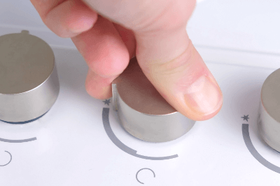
Rotary SwitchesA rotary switch is a switch that switches contact points by turning.
Rotary switches are used for volume control of audio components, knobs of microwave ovens, etc. Most rotary switches are used to switch multiple contacts, but they are sold with only one contact. Most rotary switches are used to switch multiple contacts, but switches that switch only one contact are also available. Recently, ultra-compact rotary switches have been developed, contributing to the miniaturization of audio equipment and other devices.

Uses of Rotary Switches

Rotary switches are used in a wide range of applications, from familiar home appliances to industrial equipment.

Specific applications are as follows:

  • Volume control of audio components
  • Setting the output of microwave ovens
  • Switching power and strength of electric fans
  • Switching the volume of measuring machines and communication equipment
  • Switching of control board settings for inverters, air conditioners, etc.

Recently, pendant lights that use a single-contact rotary switch to operate the power supply are also available to create a retro atmosphere. Also, in recent years, they are sometimes used as power switching switches for portable LED lighting as part of DIY projects.

Principle of Rotary Switches

A rotary switch consists of a sliding element, a case/fixed contact, and a terminal.

The sliding element moves simultaneously with the movable contacts and switches the contacts according to the operation. The switched contacts conduct two or more fixed contacts attached to the case. The contact output of the fixed contacts is output to the outside through the terminals.

Types of Rotary Switches

There are two types of rotary switches: non-shorting type and shorting type. Proper selection is necessary because the circuit may break down if an inappropriate type is chosen for the intended use.

1. Shorting Type

The shorting type is a type in which two or more contacts conduct simultaneously when switching contacts. It is characterized by the fact that there is no moment of circuit breakdown. Therefore, a temporary state of electrical connection between contacts occurs.

This type is used when temporary disconnection is unacceptable, such as in the tap-switching circuit of a transformer. The shorting type is also called make-before-break. In English, it means “connected before the contacts are separated.”

2. Non-Shorting Type

The Non-Shorting Type is a type in which adjacent terminals are completely independent of each other, and the circuit is disconnected once when the contacts are switched. In this type, when switching contacts, both contacts are electrically disconnected for a moment.

Therefore, this type is used when temporary disconnection due to switching is not a problem. In general applications, the non-shorting type is used in most cases. The non-shorting type is also called break-before-make. In English, it means “to leave before the contacts are connected.

Other Information on Rotary Switches

1. How to Use a Rotary Switch

Rotary switches are used to switch circuits by rotating the actuator. They are often used to set up digital circuits. They are used when the switching frequency is not high, for example, for setting purposes.

There are various types of rotary switches, such as those with flat actuators or shaft-shaped actuators. Depending on the shape, some products can be operated with a finger, while others require a screwdriver or similar tool.

2. Thumb Rotary Switch

Among rotary switches, there are thumb rotary switches. This is a rotary switch that uses a disk-shaped part with numbers written on the switch display. They are characterized by their ease of visual confirmation and are used for setting channels on old radio equipment.

A typical thumb rotary switch consists of parts such as a case, pushbutton, slide, rotor, printed circuit board, and mounting plate.

カテゴリー
category_usa

Wavelength Meters

What Is a Wavelength Meter?

A wavelength meter measures light’s wavelength, offering higher sensitivity than optical spectrum analyzers due to its narrow dynamic measurement range. While optical spectrum analyzers provide broader functionality, wavelength meters focus solely on measuring wavelengths, making them more affordable. The measurement reflects the wavelength in a vacuum, with a minor discrepancy from air measurements due to the air’s refractive index.

Uses of Wavelength Meters

Wavelength meters are vital for tasks requiring precise wavelength accuracy, such as characterizing optical components, measuring narrow-bandwidth light sources like lasers and LEDs, and evaluating light in optical fiber communications. They are especially common in measuring light between 1,000 and 1,800 nm, critical for optical fiber communications.

Principle of Wavelength Meters

Wavelength meters utilize physical light interference, employing Fizeau or Michelson interferometers to measure wavelength. These interferometers create interference fringes from light beams, unique to each wavelength and the optical path difference. The wavelength is calculated based on the known optical path difference and the interference pattern observed.

Other Information on Wavelength Meters

1. Wavelength Meter and Optical Fiber Communications

Essential for optical fiber communications, wavelength meters measure the 1,500 nm band, the most efficient for minimizing light loss. As the demand for bandwidth increases, wavelength meters now often measure multiple wavelengths simultaneously, with advanced models handling up to 1,024 wavelengths to support wavelength multiplexing technologies.

2. Applications Beyond Optical Fiber Communications

Wavelength meters also serve in semiconductor laser evaluation for optical communications, with models that rapidly assess single wavelengths on production lines. Additionally, they support measurements in bands below 1,000 nm for optical fiber amplifiers and cater to applications like optical coherence tomography in ophthalmology and fluorescence observation in biotechnology, with models covering 300 nm to 1,200 nm.

3. Compatibility With CW and Pulsed Light Sources

Some wavelength meters accommodate both continuous wave (CW) and high-speed pulsed light sources, which are crucial for various laser applications. It’s important to select a model based on its compatibility with the intended light source.

カテゴリー
category_usa

Flyback Transformers

What Is a Flyback Transformer?

A flyback transformer is a transformer used in a flyback converter.

It is one of the circuit methods used in isolated switching power supplies such as isolated DC-DC converters and AC-DC converters, and other types include the forward method, LLC resonance method, and push-pull method.

In the flyback method, energy is repeatedly accumulated and released into the transformer during power conversion. Therefore, unlike other types of transformers, flyback transformers must have the characteristics to store large amounts of energy.

Uses of Flyback Transformers

Flyback transformers are used in switching power supply circuits used in a variety of consumer and industrial applications. The power that can be handled by this power supply is only a few tens of watts, making it suitable for relatively low-power applications compared to isolated switching power supplies of other methods.

On the other hand, it features a wide input voltage range. It has the advantage of simple power supply circuit configuration, fewer components, and lower cost. However, the peak current is higher, so care must be taken with specifications when selecting switching elements, rectifier diodes, and other components.

Also, the ripple current is higher than in other methods, so the smoothing capacitor capacity must be larger.

Principle of Flyback Transformers

Flyback transformers are based on the principle of charging when current flows through the primary side of the transformer and discharging through the secondary side of the transformer after the current is interrupted. Due to the principle of operation, it is very important for the transformer to accumulate electromagnetic energy in terms of its characteristics.

A switching element (power transistor, power MOSFET, etc.) is connected to the primary side of the flyback transformer, and a smoothing capacitor is connected to the secondary side through a rectifying diode. The polarity of the windings is reversed so that when an excitation current is applied to the primary side of the transformer, a voltage is generated in the direction that the rectifier diode on the secondary side turns off.

When the switching element is turned on, the excitation current flows in the primary side of the transformer and electromagnetic energy is stored in the transformer. When the switching element is turned off in this state, the excitation current on the primary side is interrupted, the direction of the voltage on the secondary side is reversed, and the electromagnetic energy stored in the transformer is released through the rectifier diode. This is smoothed by a capacitor to output a DC voltage.

The flyback transformer must store a large amount of electromagnetic energy. Transformers intended for energy transmission, like other methods, use core materials with high magnetic permeability to increase the coupling coefficient. However, such materials usually cannot store large amounts of electromagnetic energy. Therefore, in flyback transformers, an air gap is created in a part of the core where the magnetic permeability is low, and energy is stored in this gap.

Other Information on Flyback Transformers

1. Difference Between Flyback and Forward Power Supplies

Flyback power supplies require a relatively large transformer because electromagnetic energy must be stored in the transformer. A minute gap is created in part of the core to lower the magnetic permeability and store electromagnetic energy. On the other hand, forward power supplies do not require such a minute gap because the transformer does not need to accumulate electromagnetic energy, and the transformer can be made smaller.

In addition, flyback power supplies do not require isolation separation of the primary and secondary feedback circuits, making the circuit configuration very simple, whereas forward power supplies require isolation and a voltage feedback circuit from the output.

2. Ferrite Material Used in Flyback Transformers

Flyback transformers are widely used in AC-DC switching power supplies due to their configuration. However, the semiconductor devices for switching and the transformer are the two areas of high loss in AC-DC switching power supplies. During high-speed switching operations, rapid magnetic flux changes occur in the transformer, and if an iron core is used for the transformer core, heat is generated due to eddy current losses, rendering the transformer unusable.

For this reason, flyback transformers for high-frequency AC-DC switching power supplies often use ferrite as their core material. Since the characteristics of ferrite are frequency and temperature dependent, it is important to select a flyback transformer with a core made of ferrite material suitable for the desired operating speed.

カテゴリー
category_usa

VME Boards

What Is a VME Board?

VME (Versa Module Europe) boards were developed as boards that use the VME bus, a bus for CPUs.

The VME bus used in VME boards was originally developed for Motorola’s 68000 series CPUs, and was later adopted as a global technical standard by the IEC (International Electrotechnical Commission) and It was later standardized as a technical standard by the IEC (International Electrotechnical Commission) and IEEE (Institute of Electrical and Electronics Engineers: a standardization organization in the electrical and information fields).

It is currently used as a standard bus for 64-bit CPUs in addition to 16-bit and 32-bit CPUs.

Usage of VME Boards

A VME board has 9 or 20 VME connectors on the motherboard, which is the foundation for connecting multiple VME boards.

This motherboard is called a VME backplane board or VME backplane chassis, and its material and size are determined to maintain its performance and quality.

The VME backplane board is very important because it electrically and structurally connects multiple VME boards through which data is transmitted and received.

CPU boards and IO boards are inserted into slots on the VME backplane board.

Principle of VME Boards

The data transfer used on VME boards is based on the asynchronous inter-clocking method, which means that data is transmitted in synchronization with the system clock. This is different from the method of sending and receiving data synchronized with the system clock.

The master side repeats data transmission and does not complete the data transfer cycle until the slave side responds with an acknowledgement signal indicating that data reception is complete.

This is advantageous and easy to design for peripheral devices that do not have sufficient transfer speed, since data can be sent and received according to the timing of the slave device.

However, it is necessary to avoid infinite transfer cycles from the master. For this purpose, the VME bus has a timeout function.

The VME bus is also designed to handle data collisions between devices on the VME bus. An arbitration module is defined as a dedicated functional module for detecting and responding to collisions, and it must be present in every VME bus system.

Two methods are defined for detecting and responding to collisions. These are the round-robin method and the priority method.

Round Robin Method

Round-robin is a method in which each device on the VME bus is sequentially assigned a number based on the number assigned to the device. For example, if there are devices A, B, and C, and the first round is A, B, and C, the second round is B, C, and A, and the third round is C, A, and B. This method determines which device has priority in the event of a collision based on the rule of sequential equal priority switching.

Priority Order Method

On the other hand, the priority method determines which device has priority in the event of a collision based on a fixed priority order for each device.

Depending on which method is adopted is determined according to the system’s application and characteristics.

Other Information on VME Boards

1. Bus

The bus mentioned in the above explanation refers to a circuit that transmits data and signals inside a computer. Inside a computer, devices such as CPU, memory, and IO devices are connected by a common bus.

There is an address bus for transmitting memory address signals and a data bus for data transfer between the CPU and memory/IO devices. There is also a control bus for controlling these two buses. The control bus is responsible for controlling the timing of actual input/output by the address bus and data bus.

2. Bus Standard

The initial development standard was a 16-bit bus standard to fit into the Eurocard connector. Later, through expansion, the current VME64 has a 64-bit bus standard and a 32-bit bus standard.

カテゴリー
category_usa

Illuminance Meters

What Is an Illuminance Meter?

Illuminometers

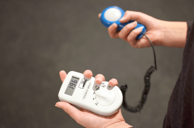
An illuminance meter is a machine that measures the brightness of a place.

In our daily lives, schools, workplaces, etc., it is necessary to have appropriate illuminance in our work environment. Illuminance is expressed in units of lux. There are two types of illuminance meters: the photocell type, which does not require a power supply, and the photoelectric tube type, which can measure illuminance down to low levels.

Principle of Illuminance Meters

An illuminance meter measures and quantifies the brightness of a lighted area, measuring the luminous flux per unit area (lm: lumens). The illuminance meter’s sensitivity to light wavelengths matches the sensitivity of the human eye, and it obeys the cosine law for light emitted at an angle. The cosine law is a law that states that the luminous intensity Iθ from an evenly diffused area to a certain direction is proportional to the cosine of the angle θ formed with the luminous intensity in the direction normal to this area. This can be expressed in terms of a conductor as follows.

Iθ = In cosθ

The light-receiving part of the illuminance meter consists of a photodiode that converts light into an electrical signal, an optical filter to match the sensitivity of the human eye, and a diffusing globe to follow the cosine law.

Regarding the sensitivity of the human eye, with a peak at 555 nm, the sensitivity of 380 to 780 nm, with a mountain-shaped wavelength selection in the region of 380 to 780 nm.

Therefore, illuminance (lux) itself is also detected within this range.

How to use an Illuminance Meter

The illuminance meter is very easy to use. Just press the measurement button on the illuminance meter, and the measured value will be displayed. Most illuminance meters are large enough to be easily carried by hand and can be easily used in a variety of situations. However, depending on how you use the meter, you may not get the correct measured value.

The following are points to be considered when using these instruments.

1. Effect of Reflected Light

Illuminance meters are affected not only by direct incident light from the light source but also by reflected light. Since the illuminance meter can be affected by reflected light from the hand, face, and clothing of the person being measured, it is necessary to take measures such as bending down as much as possible and wearing clothing with low reflectance.

2. Size of a Light Source to be Measured

When the light source of a filter-type illuminance meter is a narrow beam of light, the path of light reaching the light-receiving element varies depending on the angle, which affects the measured value. When measuring a spotlight that is smaller than the illuminance receiving area of the illuminance meter, care should be taken to consider a different measurement method.

3. Distance between Light Source and Illuminance Meter Receiver

In filter-type illuminance meters, the closer the distance between the light source and the illuminance meter is, the more the light incident on the illuminance meter is angled, resulting in an error. Normally, a distance of about 1 m or more from the light source to the illuminance meter is sufficient to avoid problems.

In addition, standards and measurement methods are established when checking for a safe and comfortable environment in schools, workplaces, factories, and other places. It is necessary to understand the purpose of use and measurement conditions of the measuring instruments and to use them correctly.

Types of Illuminance Meters

Various types of illuminance meters are based on measurement range, accuracy, and ease of use.

Analog illuminance meters are used to simply check the light intensity of fluorescent lamps and the like. They are also used when you want to fix them to a specific location and measure them periodically.

Digital illuminance meters have a wide measurement range and are useful for measuring various locations, such as indoors and outdoors. There are types with separate light-receiving and display sections, which are useful when the measurement locations are far apart. They can be used for a wide range of applications.

As for the measurement range, the range that can be measured differs from illuminance meter to illuminance meter, but some types can switch the specific range in stages.