カテゴリー
category_usa

Turbo Chiller

What Is a Turbo Chiller?

Turbo chillers are heat cycle systems that cool brine, such as antifreeze, with a refrigerant such as CFC. The cooled brine is used for air conditioning and freezers.

Turbo chillers offer the advantage of highly efficient and space-saving air conditioning installations. However, the disadvantages are that the compressor requires a certain amount of electricity, refrigerant piping needs to be installed, and a large initial investment is required. In recent years, turbo chillers using alternative CFC and non-CFC refrigerants have been developed in consideration of the environment.

Uses of Turbo Chillers

It is mainly used for centralized air conditioning of large buildings and commercial facilities. For industrial applications, they are sometimes used in facilities that require cooling. Examples of industrial applications are shown below.

  • Process cooling for textile and chemical plants that consume large amounts of cold water
  • Semiconductor manufacturing plants that need to maintain a constant temperature and humidity environment
  • District heating and cooling centrally managed on a broad regional level

In recent years, demand for these products has been increasing due to their high energy-saving performance.

Principle of Turbo Chillers

Turbo chillers, like other chillers, cool brine through a cycle of evaporation, compression, condensation, and expansion. The term “turbo type” is derived from the fact that a turbo compressor is used in the compression process. Because of its high refrigeration capacity and large size, it is used for large-scale cooling applications.

An overview of the cooling process is as follows:

1. Evaporation Process

In the evaporator, the refrigerant undergoes a phase change from a low-temperature, low-pressure liquid to a low-temperature, low-pressure gas. The brine is cooled by the heat of vaporization during this process. The cooled brine is circulated to the air conditioner.

2. Compression Process

The refrigerant vaporized in the evaporation process is compressed in a turbo compressor to become a high-temperature, high-pressure gas. In a turbo compressor, the refrigerant is compressed centrifugally by rotating an impeller.

3. Coagulation Process

The high-temperature, high-pressure refrigerant in the coagulator is cooled by the cooling water in the cooling tower, changing its phase to a medium-temperature, high-pressure liquid. The heat lost in the cooling water is released into the atmosphere in the cooling tower.

4. Expansion Process

The medium-temperature, high-pressure refrigerant is depressurized through the expansion valve to become a low-temperature, low-pressure liquid. After this, it returns to the evaporation process, and the cycle is repeated.

Other Information on Turbo Chillers

1. Difference Between Turbo Chiller and Absorption Chiller

There are various types of chillers, which are classified into two types according to refrigerant and refrigeration cycle: vapor compression chillers and absorption chillers. Turbo chillers are a type of vapor compression chiller.

Unlike the refrigeration cycle of turbo chillers, absorption chillers cool through a cycle of “evaporation, absorption, regeneration, and condensation,” with no compression process. Since absorption chillers can use both chilled water and hot water, they can be used for heating as well as cooling.

Absorption chillers use a corrosive absorption fluid called lithium bromide together with refrigerant. Therefore, if the chiller is used for a long period, its efficiency will decrease due to corrosion. In addition, since the absorption liquid contains hazardous substances, it is necessary to request a recovery company to dispose of the refrigeration unit when it is disposed of.

Since turbo chillers are more efficient as refrigeration units, they should be selected in accordance with the existing facilities and applications.

2. Difference Between Turbo Chiller and Chiller

A chiller (cooling water circulator) is a device that performs the same temperature departure as a turbo chiller. There are several differences between turbo chillers and chillers.

Chillers use brine to cool the circulating liquid, while turbo chillers use brine to generate cold air. In chillers, the circulating liquid itself freezes when super-cooled, so the temperature that can be cooled is about -10°C. In turbo chillers, the circulating liquid is cooled only by brine, and not by air. Turbo chillers are capable of not only cooling but also freezing, which makes a big difference in cooling limits.

3. Demand for Turbo Chillers

The market size of the field related to chillers, including turbo chillers, is estimated to be about 150K USD. Among these, demand in the Middle East region accounts for about 30% of the global market, and is expected to expand about six-fold by 2030. Demand for turbo chillers is expected to continue to grow in the future.
カテゴリー
category_usa

Self-Levelling Material

What Is Self-Leveling Material?

Self Leveling MaterialSelf-leveling materials are gypsum or cement-based natural flow materials.
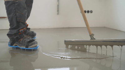
Self-leveling material is characterized by its ability to form a level and uniform level simply by pouring, and is also known as a leveler.

It is a revolutionary flooring material when compared to mortar, which has a similar role to that of self-leveling materials. While mortar finishes vary greatly depending on the skill of the craftsman, self-leveling material can be poured in and then broken in with a tonneau to complete a smooth floor base quickly.

Uses of Self-Leveling Material

Self-leveling materials are used to prepare floor subfloors with a smooth concrete surface.

Applications include buildings, condominiums, schools, hospitals, factories with heavy vehicles such as forklifts, parking lots, food factories, kitchens, and waterproof basements on rooftops. It is also used for underground adjustment in the preliminary stage of applying finishing materials such as tiles and other floor coverings.

Compared to mortar, which performs a similar function, self-leveling materials are more expensive in terms of material cost, but the short construction period helps to keep costs down.

However, it is difficult to obtain the thickness of self-leveling material in a single installation, and overlaying is required for thicknesses of 20 mm or more. In such cases, mortar is more suitable.

Principle of Self-Leveling Material

The principle of the self-leveling method using self-leveling materials is that a slurry (suspension) of gypsum and mortar poured onto the floor surface naturally flows to form a smooth floor surface.

The self-leveling process follows the following steps:

1. Preparation Before Construction

Pre-construction preparation includes level checking and marking. Marking out is the process of drawing out reference lines that serve as horizontal and central positions, such as the centerlines of columns and finished surfaces of walls. To prevent the self-leveling material from leaking outside, gaps are filled with mortar to prevent direct sunlight and wind.

2. Preparation of the Substrate

The substrate is cleaned with a special brush as a pre-treatment. Oil and protrusions are treated so that the self-leveling material and the floor can bond well.

3. Primer Application

Primer is applied and allowed to dry to provide adhesion to the subfloor surface. Primer is a base coat applied to improve the adhesion of materials that do not bite well to paint.

4. Placing Self-Leveling Material

After completing the above preliminaries, the self-leveling material is poured. When pouring the leveling material, ripples and air bubbles generated from the frame may remain as shapes, so if necessary, use a trowel to even out the material.

Details are matched to the ink or level point using a trowel. Finish by pouring gently, quickly, and evenly.

5. Curing and Drying

After pouring is completed to the finish level, the curing period begins. Avoid rapid drying until curing is complete. Close the windows to stop ventilation and reduce surface wrinkles caused by wind.

After curing is complete, the self-leveling material is still in a state of excessive moisture, so once curing is confirmed, windows are opened to improve ventilation and promote drying.

6. Finish Inspection and Rework

Finally, as a pre-completion inspection, we inspect the level of the building after it is ready for walking. We check all areas for joints, joints, and height differences. Any joints, bubbles, etc. that may have occurred will need to be corrected.

Types of Self-Leveling Materials

Self-levelling materials can be classified into two categories: gypsum-based and cement-based.

1. Gypsum-Based Self-Leveling Material

It has the property of not expanding or contracting during curing due to hydration reaction. This gypsum-based product has high dimensional stability and is resistant to floating and cracking.

2. Cement-Based Self-Leveling Material

Many cementitious materials feature high strength, and some can be used externally. After curing, they are also characterized by their resistance to water. 

カテゴリー
category_usa

Selfeel

What Is Selfeel?

Selfeel is an air catalyst that decomposes harmful substances by spraying them into the air, thereby performing deodorizing and antibacterial functions.

Nichirin Chemical Co., Ltd. started manufacturing and marketing SELFEEL in 2002. In other words, Selfeel is the trade name of Nichirin Chemical Co.

It uses only water and oxygen in the air to produce various effects. Other known catalysts include photocatalysts, but photocatalysts need light to work.

Selfeel, an air catalyst, is unique in that it can work in the absence of light, as long as there is water and oxygen in the air.

Uses of Selfeel

Selfeel is used in newly built or remodeled rooms to prevent sick building syndrome, a problem caused by volatile formaldehyde and voc contained in various building materials.

Apart from newly built or remodeled buildings, selfeel is also used in hospitals, schools, commercial stores, public facilities where many people gather, and in public transportation vehicles such as trains and railroads.

Selfeel Principle

Selfeel is a catalyst. First of all, a catalyst is a substance that promotes a particular chemical reaction while remaining unchanged itself. Even if a chemical reaction is unlikely to occur in an environment without a catalyst, the addition of a catalyst will promote the scientific reaction.

In this process, the catalyst itself is not changed. Since selfeel is an air catalyst, it uses only air for its catalytic effect. Among the air involved are water and oxygen. Specifically, potassium 40, a component in selfeel, acts on water molecules in the air to produce hydroxyl radicals (∙OH) and hydrogen peroxide.

The generated hydrogen peroxide generates hydroxyl radicals through the action of iron, titanium, and other elements in selfeel in what is called the Felton reaction. Hydroperoxyl radicals
(OOH) produced from hydrogen peroxide and superoxide ions (O2-) are also produced from oxygen in the air.

Thus, selfeel generates hydroxyl radicals from water in the air and superoxide ions from oxygen in the air. The hydroxyl radicals are then responsible for the various effects of selfeel. The action of superoxide ions generated from oxygen is a decomposition reaction in the air. This decomposition reaction kills bacteria and prevents the growth of mold.

Other Information About Selfeel

1. What Is a Radical?

Radicals are atoms or molecules with unpaired electrons. Radicals are not stable like normal atoms and electrons, and can produce a variety of reactions. Selfeel acts as a catalyst to promote chemical reactions because radicals are active ones.

After the reaction, the radicals are decomposed again into water and oxygen, which are returned to the air. In other words, water and oxygen in the air can be circulated and utilized.

2. Effect of Selfeel

Selfeel is effective in preventing sick building syndrome, which is a problem in newly constructed houses. In addition, selfeel has stain resistance, antibacterial and antifungal effects, deodorizing effects against toilet and cigarette odors, antiviral effects, and negative ion effects on interior walls.

3. Difference Between Selfeel and Photocatalyst

The only other material besides selfeel that prevents sick building syndrome is photocatalyst. Photocatalysts require sufficient light, specifically ultraviolet light, to work, and in environments where ultraviolet light is available, they are more effective than SELFEEL.

Selfeel is characterized by its ability to be effective even in low-light environments. Other advantages of selfeel are that it does not discolor or change the texture of walls, is colorless and transparent, does not require curing, is easy to work with, and is low cost.

In particular, selfeel itself is harmless to the human body. Because of its high safety, selfeel is also used in schools, hospitals, and public facilities, and can be used safely by frail people and children.

カテゴリー
category_usa

Shape Analysis Laser Microscope

What Is a Shape Analysis Laser Microscope?

A Shape Analysis Laser Microscope is a microscope that uses a laser beam to measure the surface topography of an object.

Some microscopes have the same functionality but use a contact probe such as a cantilever, which touches the surface and may damage or scratch the sample. Shape analysis laser microscopes, on the other hand, utilize light reflection, allowing non-contact inspection.

Although the optical system is the same as that of a typical confocal laser microscope, many products are available that employ a high-speed MEMS scanner or resonant scanner to obtain three-dimensional information, thereby reducing scanning time.

Uses of Shape Analysis Laser Microscopes

Shape analysis laser microscopes are used to inspect various products and search for problems. In particular, they are often used for semiconductor components and printed circuit boards, because the components themselves are very small and have an elaborate surface structure, allowing non-contact, non-destructive inspection.

Using a problem-free product as a reference and superimposing it on the image of the inspected part allows rapid detection of problem areas. Also, because it is non-contact, it can be used for soft samples, and no special pre-treatment is required, so it is also used for inspecting food products.

Principle of Shape Analysis Laser Microscopes

The microscope acquires surface shape information by emitting a laser beam and detecting its reflected light.

1. 2D Shape

Since the intensity of light attenuates with the square of the distance, monitoring the intensity of the reflected light will reveal the distance to the surface. In this case, if light from an out-of-focus object is inserted, the increase or decrease in reflected light will be averaged out, reducing sensitivity.

To prevent this, the microscope employs confocal optics with pinholes in the conjugate focal plane to cut excess light from the non-focal plane. The distance information to the surface is thus accurately obtained as two-dimensional information by scanning the laser in the X- and Y- directions.

2. Three-Dimensional Shape

Furthermore, by scanning the objective lens in the Z direction, three-dimensional 3D shape analysis can be performed. The spatial resolution in the planar direction depends on the wavelength of the laser according to Abbe’s law, as in general optical microscopy.

Therefore, if there is no problem with the sample, a near-ultraviolet laser with a shorter wavelength, such as 405 nm, can be used for high-resolution measurement.

More Shape Analysis Laser Microscope Information

1. Measurement Procedure Using a Laser Microscope

There are three main categories of microscopes: optical microscopes, electron microscopes, and scanning probe microscopes. Laser microscopy is a type of optical microscope.

The procedure from laser irradiation to image display in a laser microscope consists of the following six steps:

  • A laser is used as the light source.
  • The laser passes through the objective lens and scans the object to be measured.
  • Reflected light from the measurement object is once again incident on the objective lens.
  • A half mirror changes the path of the reflected light toward the detector.
  • A pinhole at the imaging position eliminates scattered light.
  • The laser incident on the detector is displayed as a 3D image by image processing using an amplifier, etc.

2. Surface Roughness by Laser Microscopy

Surface roughness in laser microscopy is a measure of the unevenness of a part’s machined surface. Surface roughness is a cyclic shape consisting of a series of peaks and valleys of different heights, depths, and densities (spacing).

Surface roughness changes the feel and texture of a surface. The larger the surface roughness, the rougher the surface is to the touch, and the less light is reflected. On the other hand, a surface with a small surface roughness is smooth and reflects light intensely like a mirror.

Today, the texture and feel of a product are considered important, and roughness is an important indicator for quality control of appearance. Indicators of surface roughness include arithmetic mean roughness (Ra) using average values and maximum height (Rz) using the sum of peaks and valleys.

カテゴリー
category_usa

Shape Measuring Machine

What Is a Shape Measuring Machine?

Shape Measuring Machines are devices used to record, analyze, and measure the contour shape of an object by accurately tracing the shape of its surface.

Shape Measuring Machines can be divided into two main types. The contact type uses a stylus (stylus) and the non-contact type uses a laser or other means to trace the surface. Shape Measuring Machines of the non-contact type are relatively easy to use, but they can be greatly affected by the material and properties of the object’s surface. For this reason, contact Shape Measuring Machines are the most common type.

Shape Measuring Machines have high resolution and can trace contours to 0.001 mm or less. However, measurement beyond the movable range of the stylus is not possible, so careful consideration should be given when making measurements with large height directions.

Uses of Shape Measuring Machines

Shape Measuring Machines are used in the development, production, and quality control of industrial products, particularly metals. Shape Measuring Machines are used to measure and analyze the contour of an object, including dimensions, angles, steps, and thread pitch.

Shape Measuring Machines that are CNC-controllable can be programmed to perform a series of measurement operations and used for automatic measurement on the production line. For example, standardized shapes, such as the screw shape of a plastic bottle lid, are generally quality-controlled by Shape Measuring Machines. For products whose shape itself is patented, the contour shape is specified in detail.

Principle of Shape Measuring Machines

This section describes the principle of contact Shape Measuring Machines, which are the mainstream of Shape Measuring Machines. Shape Measuring Machines plot the contour shape of the object to be measured as the displacement of a stylus attached to a horizontally moving detector and the stylus moves up and down.

While moving the stylus, the contour shape is traced by continuously plotting the X coordinate of the horizontal movement and the Y coordinate of the vertical position of the stylus at a pitch of about 0.001 mm on a digital scale.

The vertical movement of the stylus on most Shape Measuring Machines is an arc movement around a center called a pivot. Therefore, the greater the vertical movement of the stylus from the horizontal position, the greater the horizontal error caused by the arc. The stylus tip position must be detected while constantly compensating for this error.

In addition, as the stylus tip is in continuous contact with the object being measured, the stylus wears. As the stylus wears, the position of the stylus tip changes by the amount of wear. It is necessary to periodically check the stylus tip shape and make corrections according to the amount of wear.

Other Information on Shape Measuring Machine

1. Difference Between Shape Measuring Machine and Contour Measuring Machine

Shape Measuring Machines and Contour Measuring Machines usually refer to the same thing. However, there are situations in which the names must be used with strictly separate meanings, such as the following:

The strict distinction between the two is based on whether the contour measurement is continuous or discontinuous. In other words, a Contour Measuring Machine is a continuous measurement where the stylus is in constant contact, while a Shape Measuring Machine includes non-continuous measurements. For example, a shape is represented by measuring the displacement over a certain distance at equally spaced intervals and connecting the measurement points.

Since displacement cannot be measured between measurement pitches, the pitch must be shortened or supplemented by obtaining an approximate equation from the coordinates of the measurement points. Therefore, the accuracy, such as tracing power and minimum resolution to accurately measure the shape, varies depending on the fineness of the measurement pitch.

2. Handy Type Shape Measuring Machine

A handheld Shape Measuring Machine is used when measuring objects that are too large to be measured with a stationary Shape Measuring Machine or when measuring simply at the line side.

When using a handheld Shape Measuring Machine to measure a large object, it is impossible to measure the entire shape. Use a handheld type form measuring machine only for limited measurement areas, such as areas where strict dimensional tolerances are required or where changes in form can significantly affect function, performance, or safety.

3. Situations in Which a Surface Texture Measuring Machine Is Used as a Shape Measuring Machine

The measuring principle of a surface roughness measuring instrument is a combination of the horizontal X-axis and the vertical displacement of the stylus in the Z-axis direction. This is the same measuring principle used in Shape Measuring Machines, so as long as the X-axis and Z-axis are within the measurable range, it is possible to use a Surface Roughness Measuring Machine as a Shape Measuring Machine.

However, since surface roughness evaluation requires higher precision than shape measurement, the stylus tip shape and the detector must also have higher resolution.

カテゴリー
category_usa

FPGA

What Is FPGA?

FPGA, which stands for Field Programmable Gate Array, is a device that integrates logic circuits that designers can program in the field.

While dedicated logic ICs have fixed circuits and require re-design/re-manufacturing of masks when altering a portion of the circuit, FPGAs are characterized by their logic circuits that can be freely changed by the designer.

FPGAs were developed by Xilinx in the U.S. FPGAs are large-scale PLDs that can be modified countless times by writing the circuit configuration into SRAM.

Applications of FPGAs

FPGAs find applications in various sectors, including automotive devices, data sensors, and deep learning. Large-scale logic circuits are employed to perform high-speed logic operations that cannot be programmed by the CPU. One solution is to design and manufacture dedicated LSIs (such as ASICs). However, dedicated LSIs are difficult to change circuits.

On the other hand, FPGAs allow circuit designers to freely design application circuits and easily change circuits, thus significantly reducing the development cost of logic circuits. These features have made FPGAs widely used in a variety of fields.

1. Automotive Equipment

Reasons for the adoption of FPGAs in automotive equipment include shortened development cycles, flexibility for modification, and the emergence of devices that meet quality requirements. A specific example is video analysis for driver assistance systems.

Driver assistance systems need to instantly analyze real-time video signals from in-vehicle cameras to assist the driver’s operations. This requires low latency and high precision algorithms. FPGAs are suitable for this purpose because they require high-speed arithmetic processing and the electronic control functions in the device can be changed as needed.

2. Data Centers

FPGAs are increasingly being used in data centers. In particular, FPGAs are replacing CPUs to handle AI, security, authentication, real-time analysis, deep learning, and other processing. FPGAs are also being used to improve the performance of large data systems. They provide high-bandwidth and low-latency connectivity to network/storage systems to accelerate data processing. It also supports functions like data compression and fill processing, among others.

3. Deep Learning

In the world of deep learning, the flexibility of FPGAs to change circuits is extremely useful because optimal modeling is constantly evolving. FPGAs are ideal devices for applications that require frequent system upgrades, such as this application.

FPGA Principles

FPGAs are LSIs based on a structure in which programmable, relatively small-scale logic blocks are arranged in a grid with vertical and horizontal wireways between them. Although each logic block is small in scale, many blocks can be combined to form a large-scale circuit.

The basic logic block consists of a LUT (Look Up Table), flip-flops, and additional circuits. Logic blocks can be connected arbitrarily by means of a switch matrix (transfer gate) provided in the wireway.

The LUT uses SRAM for its operation. The ON/OFF of the switch matrix is also controlled by the data written to the SRAM. Since the data in the SRAM is lost when the power is turned off, the FPGA reads circuit information (configuration data) from the outside when the power is turned on.

The internal structure of an FPGA includes various components such as basic logic blocks, internal wireways, dedicated clock routing, multiplier (DSP), I/O section, PLL, and block RAM. These are arranged in a mesh pattern for easy routing of any circuit pattern.

Other Information on FPGAs

1. Design Tools

Traditionally, RTL (Register Transfer Level) has been used as the design language for FPGA design. Based on the designer’s RTL, a download file to be written into the FPGA was generated from the tools provided by the FPGA vendor.

In recent times, however, FPGA vendors have released tools called high-level synthesis compilers. By using this high-level synthesis compiler, efficient design is possible, and at the same time, circuit verification time is reduced. As a result, it contributes to shortening the product development time.

Presently, FPGA vendors offer the following three high-level synthesis compilers.

  • Model-based (DSP) compilers.
  • HLS compiler
  • OpenCL compiler

Evaluation boards are usually used to study circuits using FPGAs. These are sold by a variety of companies, including semiconductor vendors, evaluation board manufacturers, and contract design companies. Therefore, there are a wide array of evaluation boards, and it is necessary to select the one that best suits your technical level and purpose. The following six are representative manufacturers:

  • HiTech Global
  • BittWare
  • TUL
  • IOxOS
  • Portwell Japan
  • ANVENT

2. Market

According to an April 2020 report by Global Information, Inc., the FPGA market is projected to reach US$8.6 billion by 2025, a significant increase from the US$5.9 billion recorded in 2020. This growth is anticipated to be driven by a compound annual growth rate (CAGR) of 7.6%. While specific figures for each technology node are not provided, it appears that in 2019, the majority of FPGA products fell below the 28 nm technology node in terms of market share.

Furthermore, the forecast indicates that the market for sub-28nm products will continue to show high growth in 2025 due to the emergence of low-power products, etc. The applications that will drive the FPGA market from 2020 to 2025 include high-performance computers for cloud computing and 5G networking. The applications driving the FPGA market from 2020 to 2025 include high-performance computing for cloud computing and 5G networking.

カテゴリー
category_usa

High Frequency Heating Equipment

What Is High Frequency Heating Equipment?

High-Frequency Heating Equipment is a type of heat supply system that utilizes the principle of induction heating and uses a high-frequency oscillator as its energy source.

Generally, it is a direct heating system for metal, but it can also heat other materials through that metal.

Uses of High-Frequency Heating Equipment

High-Frequency Heating Equipment has been introduced in metal metallurgy and other situations where heat treatment is required. Compared to conventional heating systems such as gas furnaces and electric furnaces, High-Frequency Heating Equipment can be made smaller, making it suitable for situations where space-saving is required.

In addition, the heating method of applying an electric current to the metal itself produces almost no by-products such as scale, making the furnace a perfect match for use in clean room environments such as semiconductor manufacturing facilities.

High-Frequency Heating Equipment can be used to uniformly heat metals to high temperatures until they are melted.

Principle of High-Frequency Heating Equipment

A coil is wound around the object to be heated, and an AC power source is connected to the coil via a high-frequency oscillator. When the metal to be heated is inserted into the coil, eddy currents are generated on the surface of the metal, and the metal is heated by the Joule heat generated by the current.

In principle, only metals can be heated directly, but it is also possible to heat water indirectly by heating the metal to the point that it does not melt and bringing it into contact with the water. Of course, other individual substances can be used instead of water.

In addition, the heat input can be controlled relatively easily by adjusting the input value of the high-frequency oscillator, and when the metal is melted, eddy currents continue to flow in the molten metal itself, which also acts as a self-stirring force.

How to Select High-Frequency Heating Equipment

If you need to heat metals in a clean environment, we recommend that you consider installing High-Frequency Heating Equipment. In doing so, it is important to confirm that the shape of the coil for heat input is appropriate for the size of the material to be heated. If the metal to be heated does not fit inside the coil, it cannot be heated, of course.

It is also necessary to check the output of the high-frequency power supply according to how fast you want to heat the material. Since the heating device utilizes Joule heat from eddy currents flowing on the surface of the metal, if the maximum output power is low, it will take a reasonable amount of time to heat the metal.

Other Information on High-Frequency Induction Heating

1. Advantages of High-Frequency Induction Heating

The feature of high-frequency induction heating is that it heats by generating heat from inside the object to be heated through resistance heating using electromagnetic induction. The following five are the advantages of this feature.

Uniform Heating
Since this type of heating utilizes the electrical resistance of the object itself, the entire interior of the product is heated uniformly and evenly. This is a great advantage for materials with poor thermal conductivity or products with large heat capacity that require a long time to become uniformly heated by external heating.

Rapid Heating
High-frequency waves can be given instantaneously by controlling the transmitter, and since the heating is internal, the object to be heated can be heated rapidly. Compared to external heating, which takes time to equalize heat, this heating method offers superior productivity.

Selective Heating
Even if the object to be heated is a composite component consisting of several types of materials, only the portion of the component made of a material with high electrical resistivity can be selectively heated.

Atmosphere Selection and High Energy Efficiency
The furnace does not heat the heating element, atmosphere, or furnace structure as in the case of external heating by combustion, but only the object to be heat-treated generates its heat. Another major advantage is that high energy efficiency can be achieved because the heating is done only for the object to be heated without any waste.

2. Disadvantages of High-Frequency Induction Heating

High-frequency induction heating has four disadvantages, namely:

Expensive Capital Investment
High-frequency induction heating has high energy efficiency and low running costs but has the disadvantage of high initial capital investment costs due to the high cost of high-frequency power supplies and equipment to prevent electromagnetic radiation leakage.

Low Shape Selectivity
To heat an object uniformly and to the required temperature, it is necessary to make the electric field of the object to be heated uniform. Therefore, while there is no problem with highly symmetrical objects such as cylinders, it is difficult to uniformly heat objects with complex shapes such as square timbers and gears.

Local Heating
Localized heating in corners and other areas can lead to overheating, which can result in failure to provide the required properties, or in the worst case, can cause problems such as melting during processing.

Individual and Partial Heating
High-frequency induction heating is a method of heating the entire or only a portion of the material to be heat-treated using an arbitrarily shaped coil, so it is a one-piece flow process. Therefore, it is a one-by-one process, which has the disadvantage of reducing productivity depending on the product and production conditions, since it does not allow batch-type mass simultaneous processing like external heating.

3. Notification of High-Frequency Heating Equipment

High-Frequency Heating Equipment, as the name implies, uses a high-frequency power source. According to the Radio Law, Industrial High-Frequency Heating Equipment that uses a high-frequency power source of 10 kHz or higher requires, in principle, an installation permit. Installation permission is required before installation, so plan accordingly. Some manufacturers may apply on your behalf, so it is recommended that you confirm this when selecting a supplier.

カテゴリー
category_usa

Linear Regulator IC

What Is a Linear Regulator IC?

Linear-regulator-IC-1.png

91_IC-Linear-Regulators_リニアレギュレータIC-1.png

Figure 1. Types of linear regulators

A Linear Regulator IC is an electronic component that outputs a stable voltage.

A constant voltage is output from the output terminal by using the voltage drop of a resistor or semiconductor device in relation to the input voltage. Since a small output voltage relative to the input voltage results in a large voltage difference loss, linear regulator ICs are used as power supplies for circuits and sensors that operate with low power consumption.

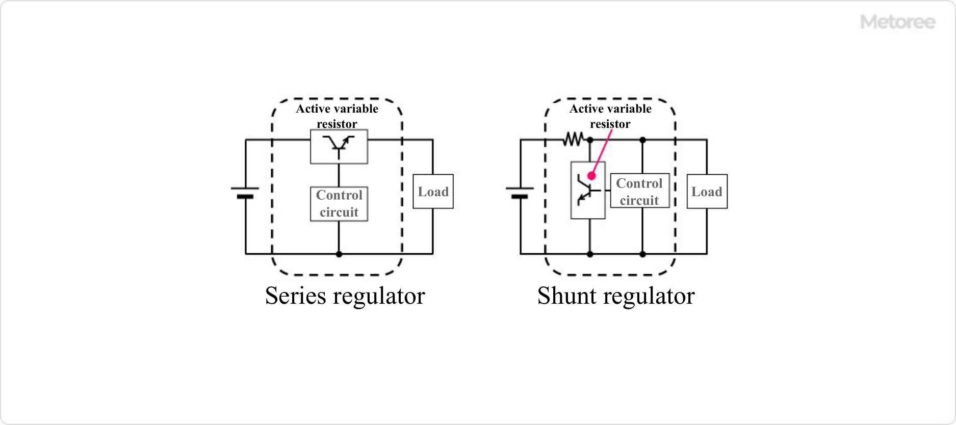
Among Linear Regulator ICs, a series regulator is an active variable resistor IC using semiconductor elements connected in series, and a shunt regulator is an active variable resistor IC connected in parallel.

Uses of Linear Regulator ICs

Linear Regulator ICs are used as the power supply part of electronic equipment and precision instruments that operate on low power. Because of the simplicity of their circuits, many products are available in low price ranges, and they are characterized by excellent stability of the voltage of the power supply they supply and low noise.

Among Linear Regulator ICs, Series Regulator ICs should not exceed the absolute maximum operating temperature of the IC because of the heat generated during the voltage drop with active variable resistor elements. If the regulator IC generates a lot of heat, measures such as attaching an external heat sink must be taken if necessary.

Principle of Linear Regulator ICs

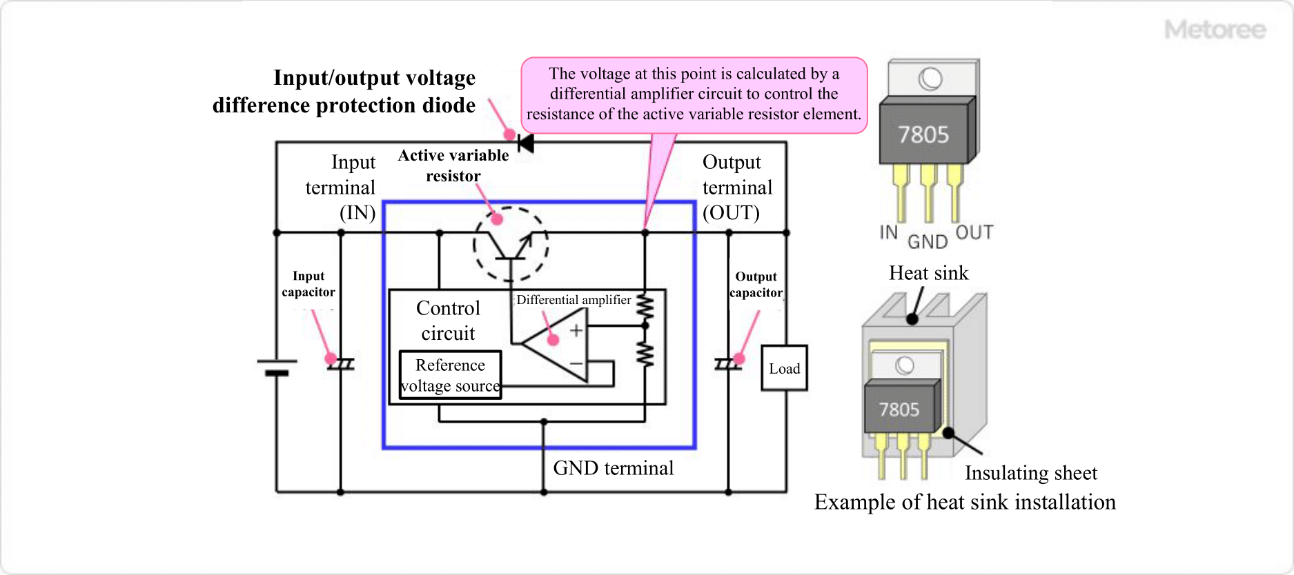
Linear Regulator ICs are one of the most common 3-terminal regulators. 3-terminal regulators have three terminals: input, output, and ground. 3-terminal regulators have the same basic structure.

A power supply is connected to the input terminal, an input capacitor is connected between the input terminal and ground, and an output capacitor is connected between the output terminal and grant so that a constant voltage is output from the output terminal.

91_IC-Linear-Regulators_リニアレギュレータIC-2.png

Figure 2. Principle of the three-terminal regulator

Inside a Linear Regulator IC is a control circuit consisting of an active variable resistor element using transistors or FETs and a reference voltage source. The control circuit measures the voltage passing through the active variable resistor element, performs feedback control, and controls the resistance value of the active variable resistor element, thereby controlling the magnitude of the voltage output from the output terminal to a certain level.

Because active variable resistor elements generate a voltage drop above a certain voltage, an input voltage that exceeds the minimum difference between the input voltage and output voltage, called the dropout voltage, is required to output a stable power supply. Normally, this is about 1.5 V. However, the IC should be selected with attention to the minimum input voltage.

Other Information on Linear Regulator ICs

1. Precautions for using 3-Terminal Regulators

Heat Dissipation of 3-Terminal Regulators
The product of the voltage difference between the input and output terminals and the current flowing from the output terminal (output current) generates heat inside the regulator and consumes power. Therefore, the larger the difference between input voltage and output voltage, and the larger the output current, the more heat is generated.

Therefore, heat dissipation design is an important factor when using 3-terminal regulators. To dissipate heat efficiently, an appropriate heat sink should be designed and attached to the 3-terminal regulator.

Board Design of 3-Terminal Regulators
The 3-terminal regulator operates to constantly output a stable voltage by feeding back the output voltage. Therefore, the capacitors connected between the input pin and GND and between the output pin and GND are very important. In particular, if the capacitor on the output pin is not appropriate, the output voltage may be transmitted.

In general, the capacitor recommended by the manufacturer of the 3-terminal regulator should be selected, but even in this case, the capacitor should be placed as close to the 3-terminal regulator as possible, and the board pattern between the 3-terminal regulator and the capacitor should be shortened in the board design.

Protection of 3-Terminal Regulator
If some abnormal voltage is expected to be applied to the input or output, a circuit to protect the 3-terminal regulator is required. If there is a possibility that an instantaneous high voltage may be applied to the input side, add a damping resistor or a Zener diode to the input to clamp that high voltage.

Countermeasures are also required when the input voltage may drop below the output voltage. If for some reason the input voltage drops significantly, a capacitor with large capacitance must be connected to the output terminals to maintain a constant output voltage. As a corollary, the output terminal voltage may temporarily be higher than the input terminal voltage when the power supply is turned off, for example.

Also, in a circuit that combines multiple power supplies, there is a possibility that the output voltage may be higher than the input voltage due to the power supply circulating from other power supplies. As a countermeasure, a protective diode (input side connected to cathode and output side connected to anode) can be added to allow current to flow from the output terminal to the input terminal.

2. Features of LDO Type Regulator

91_IC-Linear-Regulators_リニアレギュレータIC-3.png

Figure 3. Features of LDO-type regulators

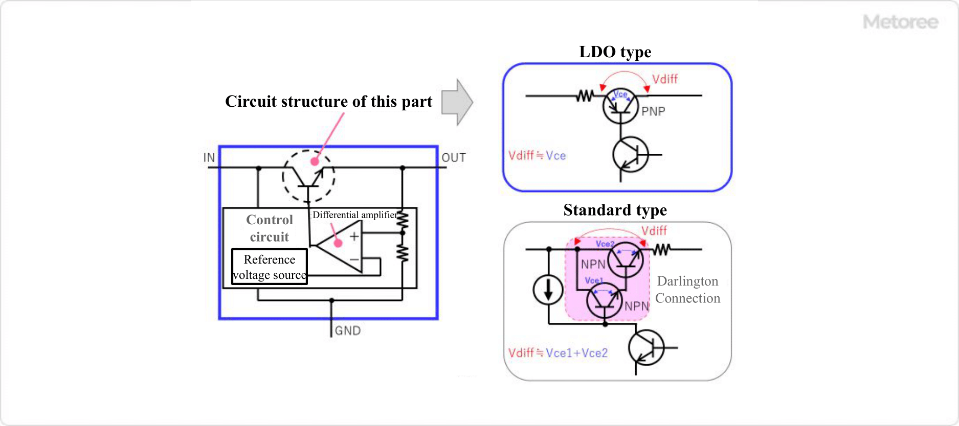
Three-terminal regulators are classified into “standard type” or “LDO type” according to the magnitude of dropout voltage (the amount by which the output voltage drops relative to the input voltage).

The dropout voltage of the standard type is about 3.0V, while the LDO type is characterized by a dropout voltage of less than 1.0V, which is smaller than the standard type. LDO” is an abbreviation of “Low Drop Out. When the combination of 12V input voltage and 5V output voltage was common, 3-terminal regulators were widely used to convert 12V to 5V. In this case, standard regulators with a dropout voltage of about 3V could be used without problems.

However, when 3.3V digital ICs became mainstream and the input voltage was 5V and the output voltage was 3.3V, LDO-type regulators became indispensable to convert 5V to 3.3V on the board. The standard type output circuit using bipolar transistors consists of two NPN transistors with Darlington connections, but the LDO type output circuit uses a single PNP transistor. This allows operation with a small dropout voltage.

However, the negative feedback characteristics have also changed, and the LDO type has a narrower stable operating range and is more prone to oscillation than the standard type. Therefore, the capacitance and ESR (equivalent series resistance) characteristics of the capacitor connected to the output pin are extremely important factors for the LDO type.