What Is Circuit Design Software?

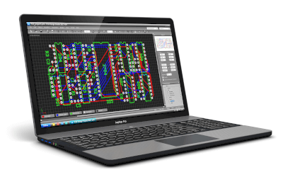
Circuit design software aids in the creation of integrated circuits, electronic devices, and electrical circuits.
Often associated with circuit design support hardware, this software is also referred to as EDA (electronic design automation). It accelerates development and ensures a safe, error-free design process by partially automating the electronic device design process, which was traditionally performed manually.
In the era of manual design, designs were drafted using circuit diagrams. However, with circuit design software, the design process involves defining functions in a specific design language, which is then automatically translated into circuit designs.
Uses of Circuit Design Software
Circuit design software finds application across all fields involved in the design and development of electronic and electrical circuits. Semiconductor manufacturers utilize it in various design stages, including device, integrated circuit system, architecture, logic, circuit layout design, and simulations at each phase.
The software also proves beneficial in designing printed circuit boards for servers, IoT devices, medical equipment, industrial machinery, and telecommunications gear, facilitating the arrangement and routing of electronic components on boards and testing their functionalities.
Principles of Circuit Design Software
Designing with circuit design software follows this sequence:
1. Design Using HDL
Initially, required functionalities are defined using a hardware description language (HDL), like Verilog. This step is typically performed manually by designers, not by the software itself.
Although some systems can convert from a higher-level system design language to HDL automatically, this system-level design is usually conducted manually.
2. Conversion to Logic Circuits
Following HDL design and verification through a test bench to ensure the design functions as intended, the software synthesizes the HDL into a logic circuit. It utilizes a library of existing device information to automatically select suitable devices according to design rules.
3. Simulation
The software simulates the synthesized logic circuits to confirm they perform as required, akin to a test bench post-HDL design. This verification stage includes device timing information from the library, ensuring the functional verification extends beyond simple signal value checks to include states where signal values are undefined (X).
4. Layout Design
Upon verification that the logic circuit meets functional requirements, an efficient layout of devices on a defined-size chip or board is conducted, along with signal routing. This phase is known as layout design, typically outside the purview of circuit design software.
Other Information on Circuit Design Software
Types of Hardware Description Languages
Hardware description languages in circuit design fall into two categories: Verilog and VHDL.
1. Verilog
Verilog’s syntax is similar to that of C and Pascal, offering a more concise format than other HDLs, making it more accessible for beginners. It was standardized as IEEE 1364 in 1995.
2. VHDL
VHDL, resembling ALGOL and Ada in notation and syntax, employs strict data types, posing a learning challenge for beginners. It was standardized as IEEE 1076 in 1987.
HDL differs fundamentally from software programming languages. In software programming, processes execute sequentially, in the written order, due to the single CPU execution model that does not support parallel process execution. Conversely, HDL-described circuits operate concurrently, as hardware components can function as soon as they receive an input signal.