カテゴリー
category_usa

Sheet Metal Working Presses

What Is a Sheet Metal Working Press?

Sheet metal working presses are thin sheets of metal that are stretched into various shapes to suit the purpose.

There are two types of sheet metal working presses: manual sheet metal working by hand using tools, and mechanical sheet metal working by machine. Sheet metal working presses are processed mainly by drawing development, punching/cutting, pretreatment, bending, welding, finishing, and inspection processes.

In both manual and machine sheet metal working, it is important to understand the characteristics of the material, sheet metal working presses. Metal materials have two characteristics, “elastic deformation” and “plastic deformation,” and these are used to form the desired shape.

Uses of Sheet Metal Working Presses

Sheet metal working presses are a processing technology used in various industries. They are mainly used in the automotive, construction, and precision equipment industries.

1. Automotive Industry

Sheet metal working presses are used for automobile bodies and interior parts. For example, cutting and welding in the manufacturing process are sheet metal working presses.

Sheet metal working presses are also used in the repair of automobiles. For example, if the body of an automobile is dented in an accident, it can be repaired by a repairman’s sheet metal working press technique.

2. Construction Industry

Sheet metal working presses are indispensable in the construction industry. For example, sheet metal working presses are used for roofs, exterior walls, and piping required for residential construction.

Sheet metal working presses are also used in various parts of infrastructure facilities. For example, sheet metal working presses are used for road signs, traffic signals, signboards, escalators, and so on.

3. Precision Equipment Industry

Among industrial products requiring sheet metal working techniques, sheet metal working used in the manufacturing process of precision equipment is called “precision sheet metal working presses.” The heat of the material is as thin as several millimeters, and fine processing technology is required.

For example, precision sheet metal working is required when making threads on a sheet of metal as thin as one millimeter. This technology is indispensable for parts of smartphones, drones, etc.

Principles of Sheet Metal Working Presses

Sheet metal working presses are made of metal, which is a material used for sheet metal working. The atoms of aluminum for aluminum and iron for iron are arranged in a regular pattern, and each atom is held together by a bonding force that attracts each other. When deformed by an external force that does not exceed the bonding force of the metal, the metal’s property causes it to return to its original state before deformation. This is “elastic deformation.”

When an external force exceeding the bonding force of the metal is applied to prevent this elastic deformation from occurring, the regularly arranged atoms become misaligned and deformed. This is “plastic deformation.”

Sheet metal working presses are a processing method that utilizes this property of metal. If force is continually applied to a metal material that no longer deforms elastically in order to create the desired shape, the material will be damaged. It is important to adjust the force applied while assessing the condition of the metal.

Types of Sheet Metal Working Presses

Sheet metal working presses include bending, cutting, tapping/burring, and welding.

1. Bending

Typical bending processes include L-bending, V-bending, U-bending, and hemming bending. Each of these processing methods is used to obtain the desired bending shape by selecting a die according to the shape to be processed.

A machine tool called a bender is widely used in the manufacturing process. In the bending process, the workpiece must have an allowance for gripping. Therefore, a gripping allowance for bending must be provided at the design stage.

2. Shearing

This process roughly cuts the material using shearing machines, such as shearing machines. In the next step, a punching die or a laser is used to obtain the shape according to the part shape. Turret punch press machines and laser cutting machines are widely used in the process of obtaining shapes by punching.

Burrs occur on the cut surface, which must be deburred using a file, grinder, or belt sander. Post-processing, such as burn removal, is necessary to remove burrs.

3. Tapping/Burring Process

If the workpiece requires a female thread, the shape can be obtained by tapping or burring. If the tapping process does not provide sufficient clearance for the screw, the burring process is used to secure clearance for the female thread, and then the female thread is machined.

When burring is performed, the back side of the machined surface becomes convex, so care must be taken to avoid interference or a reduction in clearance when assembling.

4. Welding

Sheet metal working presses are welded when it is desired to increase airtightness by integrating parts, or when fixing with screws is not possible (or is not desired from the standpoint of the number of parts).

There are three main welding methods: fusion welding, pressure welding, and brazing. Depending on the required strength and productivity, different welding methods should be used for different sheet metal parts. Surface treatments, such as pickling, are also widely used to remove discoloration and blackening due to weld burns.

Other Information on Sheet Metal Working Presses

1. Differences in Workability by Material

The workability of metal materials depends on the structure of their crystal lattice. Aluminum, torso, gold, and silver have an atomic structure called a face-centered cubic lattice, which resembles a matchbox structure and is easily deformed when external force is applied.

Iron has a body-centered cubic lattice, with atoms in the center of the matchbox structure, which increases strength and makes deformation somewhat more difficult. Magnesium is made of a compact hexagonal lattice, and its hexagonal arrangement of atoms makes it very strong and almost impossible to work at room temperature.

2. Types of Hand Sheet Metal

Polishing of Material Surfaces
This is the process of finishing with sandpaper to eliminate irregularities on the surface of materials, such as in the repair of automobile exterior panels and machine tool beds.

Cutting of Materials
Using metal shears, cut large sheets of commercially available standard size into the necessary size for forming products.

Stretching/Drawing With a Hammer
When forming a three-dimensional shape from a metal sheet, the process of stretching the material with a hammer is called “overhanging,” while the process of drawing the material to form small folds, which are then flattened and shrunk to give a deformation is called “squeezing.”

3. Types of Machining

Drilling With a Punch Die
Punching and molding are performed by selecting the necessary dies from general-purpose shear dies of various sizes, such as round and square dies.

Blanking Process by Laser, etc.
This is a machining method that uses a laser heat source to cut sheet metal working presses at high speed and with high precision.

Press Processing
A metal sheet is placed between the up-and-down male and female dies on a large machine frame. The male die descends and mates with the female die to form the sheet metal as molded.
カテゴリー
category_usa

Lathe Work

What Is Lathe Work?

Lathe work is a machining method using a machine tool called a lathe.

The workpiece is placed in the jaws of the machine tool, called a chuck, and the spindle is rotated by a drive motor built into the lathe.

Uses of Lathe Work

Turning is used in a wide range of applications as a general cutting process. Since it is a machining method suitable for machining shafts, it is often used for precision machining of shafts and screws.

On the other hand, it is necessary to optimize the lathe Work, tool selection, machining oil selection, rotational speed, feed rate, and other machining conditions according to the shape of the workpiece, and a certain degree of skill is required to perform high-precision machining.

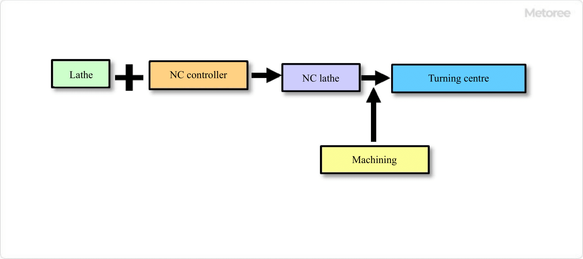
Manual lathe work is not suitable for mass production because the operator must perform multiple processes. In recent years, NC lathes (NC machining) and CNC lathes, which perform cutting based on numerical data from CAD design data and automatically calculate cutter paths, are used to achieve high precision and mass production.

Principles of Lathe Work

There are several types of lathe work, depending on the size of the workpiece and the application.

  • Front Lathe
    This is a commonly used machine tool that performs front turning.
  • Vertical Lathe
    Lathe Work is performed by fixing the workpiece on the worktable, rotating the worktable, and moving the tool that moves vertically, horizontally, and laterally.
  • Desktop Lathe
    This is a small lathe that can be installed on a workbench and mainly lathes small-diameter workpieces or products with low lathe work.
  • NC Lathe
    Lathe Work is a lathe Work that can process complex shapes stably by numerically controlling the path of the byte.

Features of Lathe Work

1. Machining Method

Lathe work is performed while rotating the workpiece (base material). The workpiece is symmetrical, and roundness, diameter, dimensional accuracy, and shape accuracy can be obtained. However, there is a trick to the chucking method, and the workpiece must be adjusted to less than the required accuracy before machining.

Cutting tools must be selected with the most suitable material and cutting edge shape for the workpiece, and the feed speed of the workpiece, spindle speed, and the method of applying machining oil must be optimized. If a three-dimensional shape is required, machining must be performed in combination with a milling machine.

2. Machining Considerations

The workpiece can be made of various metal materials, resin materials, wood, ceramic materials, etc. In order to process the workpiece, it is necessary to consider the hardness of the material, deformation of the workpiece due to processing heat, and centering of the workpiece, and then select the appropriate rotational speed of the workpiece, tool feed speed, cutting depth, cutting order, tool selection, and cutting oil type and oil application method. In addition, there are several machining methods depending on the method of applying the tool to the workpiece.

  • Periphery Cutting
    A tool is pressed against the outer circumference of the workpiece to cut it.
  • Internal Grinding
    While the inside of the workpiece is removed, a tool is applied to the inside of the workpiece.
  • Threading
    A special tool and threading feed are used to create a thread shape.
  • Drilling
    A drill is applied to the rotating workpiece to drill a hole in the center of the workpiece.
  • Plunge Drilling
    A dedicated tool is pressed against the workpiece to cut and groove the workpiece.

Other Information on Lathe Work

1. Safety Precautions During Lathing

Since the workpiece rotates during lathing, accidents such as entrapment in the chuck or being caught in the internal pulley may occur. The following are points to be considered for safety.

  • Pay sufficient attention to the chucking of the workpiece and the attachment of the tool.
  • Do not use cutting conditions with a large depth of cut or ultra-high speed rotation.
  • Be sure to wear protective equipment and safety glasses when working, as chips may scatter during cutting.
  • Do not place unnecessary tools around the Lathe Work machine, as there is a risk of entrapment or being caught in the machine.
  • When lathe work is being performed, do not wear military gloves, etc., and be careful of entrapment accidents.

2. Cutting Tools for Lathe Work

Lathe work uses a cutting tool called a tool bit. The most suitable bit is selected according to the workpiece to be machined, the difference in machining methods, and the work process.

Byte Structure

  • Muku Turning Tool Bit
    This is a turning tool bit. The cutting edge is formed by a grinder and used.
  • Brazed Turning Tool Bit
    These are turning tool bits with brazed cutting edges. There are several types, and the cutting edges can be formed into any shape.
  • Throw-Away Tool Bit
    Consists of a holder that holds the insert and a processing insert. The inserts for the dedicated holder are used by changing them according to the processing. The shape and material of the insert are selected according to the workpiece to be processed and the processing method.

Bit Types

  • Single-Edge Tool
    For external and end-face machining.
  • Sword Turning Tools
    Sword-shaped tool. Performs external and end-face processing.
  • Plunge Cutting Tool
    Used to cut off a workpiece.
  • Threading Tool
    Used for threading.
  • Knurling
    Knurling tool is used for knurling.
カテゴリー
category_usa

Punching

What Is Punching?

Punching is a process in which a workpiece (workpiece) is held in place and a rotary tool such as a drill is used to drill a cylindrical hole in the workpiece.

In general, punching includes not only simple drilling but also “reaming” to finish the inside of the hole and “tapping” to thread the inside of the hole.

Uses of Punching

Punching is performed using a variety of drills on workpieces such as wood, steel, aluminum, and steel plates. It is important to select the appropriate drill and cutting method for the material and plate thickness to be processed.

1. Basic Punching

Punching of a workpiece is performed using a variety of drills. Work that penetrates to the outside of the workpiece is “through hole” drilling. Drilling that stops halfway through is called “stop drilling.”

2. Boring

This is a method of adding a wider hole of about 1 mm in depth to the drilled screw hole to hide the screw head and ensure tightening of the screw. In this case, a tool such as an “end mill” is used for machining threaded holes made by forging or casting.

3. Reaming

This is a machining method to finish the inside of a hole drilled with a drill smoothly and precisely. A bar-shaped tool called a “reamer” is used here to improve surface roughness and roundness by contacting the inside of the drilled hole. The “cutting edge” of the “reamer” is continuously rubbed against the workpiece to enable high-precision machining.

4. Tap Processing

This is a method of making a screw in a hole drilled using a drill. A spiral thread tool called a “tap” is inserted into the hole while rotating to create threads.

Principle of Punching

Punching consists of drilling a hole in a fixed material with a tool such as a drill or reamer. The drilling process involves drilling a hole by rotating the blade and cutting away the part of the workpiece that is in contact with the workpiece.

Since chips are produced in principle, the drill has a lead section to discharge chips, a shank section to attach to a holder, and a twist drill section to drill a hole.

Types of Punching

There are five main types of punching: shallow punching, deep punching, solid drilling, trepanning, and counterboring.

1. Shallow Punching

Shallow drilling is a drilling method for holes that are less than three times as long as the drill diameter. This process is often used in wood processing.

2. Deep Punching

This is a drilling method that exceeds 10 times the length of the drill diameter. Punching should be performed under close observation as there is a risk of breaking the drill during the process.

3. Solid Drilling

Punching of a solid (raw) workpiece.

4. Trepanning Process

This is a method of drilling around the hole, leaving a cylindrical core in the center of the hole. This method is used to penetrate a workpiece in order to leave a core in the hole.

5. Counterboring

This is a machining method to enlarge a hole that has already been machined. The finished surface inside the drilled hole is machined with even higher precision.

Other Information on Punching

Machines Used in Punching

There are five main types of machines used in punching: drilling machines, lathes, milling machines, machining centers, and turning centers.

1. Drilling Machine
Drilling machine is a typical machine for punching. NC drilling machines equipped with NC devices can be controlled by NC programs (NC machining).

2. Lathe
Punching can be done by attaching a drill or boring to a lathe. Some lathes are equipped with NC devices.

3. Milling Machine
Punching can be performed by attaching a drill to a milling machine and rotating the drill.

4. Machining center
Machining centers are NC machine tools that perform a wide variety of machining operations without replacing the workpiece. Punching can be performed on a workpiece by attaching a milling machine or a drill. Normally, 3-axis machining centers are used, but 5-axis machining centers, which add two axes (rotation and tilt axes), can perform three-dimensional machining and complex machining.

5. Turning Center
A turning center is a machine with more functions than an NC lathe, equipped with a rotary tool and ATC (automatic tool changer), etc. Punching can be performed on a workpiece by attaching a drill or a milling machine.

カテゴリー
category_usa

Electron Beam (EB) Machinery

What Is Electron Beam Machinery?

Electron beam (EB) machinery is a process in which an electron beam is applied to a workpiece in a vacuum at a high heat (approximately 6,000°C).

When an electron beam accelerated to tens of thousands of volts or more is focused by an electron lens and irradiated onto a material, the kinetic energy of the electrons is converted into thermal energy, which generates high heat. The high heat can be used to process fine wiring in various high-melting point metals, jewelry, and semiconductors. In addition, because processing is performed in a vacuum, there is no risk of contamination or oxidation of the processed surface compared to processing in air, but the workability is lower.

The latest processing technology has developed a method in which the workpiece is processed outside of a vacuum, instead of in a vacuum.

Types of Electron Beam (EB) Machinery

Electron beam (EB) machinery mainly includes electron beam welding, electron beam machinery, electron beam deposition, and electron beam lithography.

1. Electron Beam Welding

In this method, electron beams generated from an electron gun are focused by a deflecting coil using a magnetic field and applied to a material. The surface of the material to which the electron beam (EB) machinery is applied is then melted by high heat, and the workpiece is processed.

Workpiece processing has conventionally been performed in a high vacuum, but a low-vacuum method with improved productivity has also been developed. It is used for sealing quartz crystal units, various aircraft parts, and electronic components that require welding in a vacuum.

2. Electron Beam (EB) Machinery

Electron beam (EB) machinery is a method of drilling and grooving minute holes or grooves by applying a focused electron beam to a localized spot on the workpiece surface and vaporizing the surface material instantaneously. This drilling process is capable of drilling holes with diameters of several tens of micrometers. It is used for drilling and grooving of difficult-to-process metals, such as stainless steel and molybdenum, as well as quartz and ceramics.

3. Electron Beam Deposition

The metal to be vapor-deposited is placed in a vacuum apparatus and irradiated with an electron beam to melt and evaporate it. Next, a workpiece to which the vapor-deposited metal is attached is placed on the side opposite the metal, and the vapor-deposited metal vapor is used to form a metal thin film on the surface of the workpiece. This method is used to produce thin films for semiconductors and ITO glass, and to prepare analysis samples for use in electron microscopes.

4. Electron Beam Lithography

This method is used in the formation of electronic circuits that require fine wiring patterns, such as semiconductor circuits. The wiring patterns of semiconductor integrated circuits are becoming finer and finer every year, requiring the formation of many component circuits and precision wiring processing on silicon wafers. Conventional semiconductor circuit processing used the photolithography method (photo-etching technology), which uses a photo mask.

The circuit pattern resolution formed by this photolithography is limited to 0.1 micrometer, and when finer wiring patterns are required, direct drawing with an electron beam is used. This method is used in the manufacture of semiconductor circuits that require state-of-the-art, fine pattern processing.

カテゴリー
category_usa

NC Machining

What Is NC Machining?

NC Machining is a machining technology based on Numerical Control.

In recent years, in order to reduce costs at manufacturing sites, it has become necessary to improve the machining accuracy and work efficiency of machine tools, and to solve the shortage of labor at manufacturing sites. NC Machining allows for stable machining accuracy and mass production of parts without depending on the intuition and skills of skilled operators.

NC Machining was first introduced by John T. Parsons in the U.S. as an NC milling machine with a built-in servo mechanism. Subsequently, NC Machining technology was greatly developed in Japan, and in 1958, Fujitsu and Makino Milling Machine Mfg. developed the first NC Milling machine produced in Japan. Furthermore, automatic tool changers were developed in the U.S. in 1959, resulting in a significant reduction in machining time.

In the future, more advanced NC Machining technology incorporating artificial intelligence is expected to develop.

Applications of NC Machining

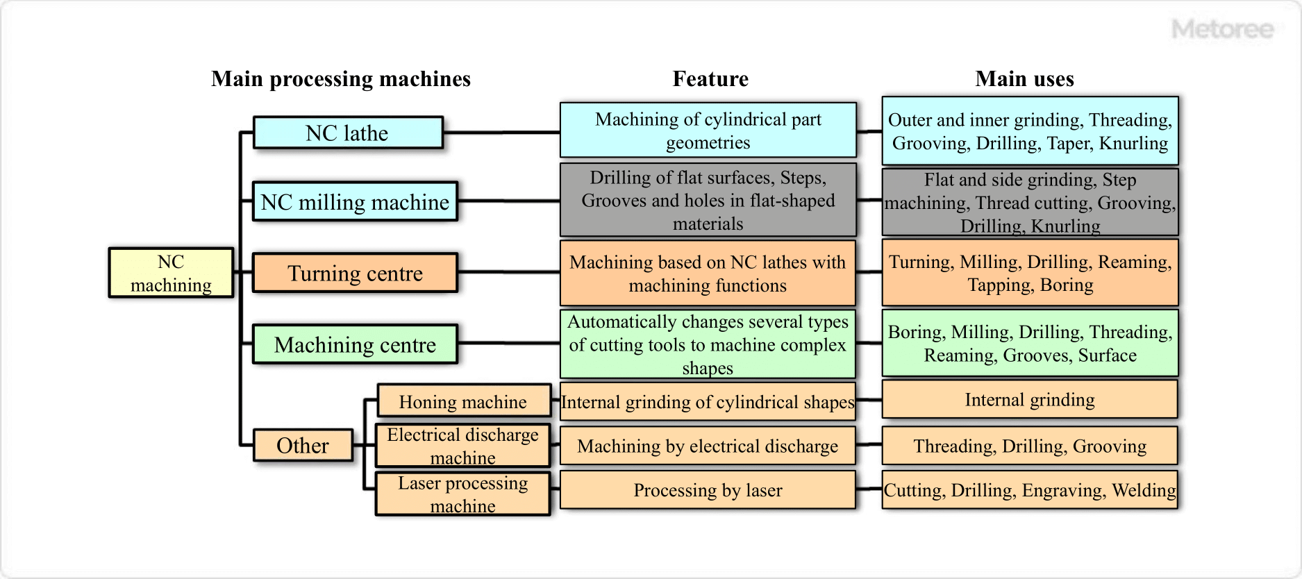
Figure 1. Types, features and uses of NC machining

Figure 1. Types, features and uses of NC machining

1. NC Lathe

The NC Machining lathe is mainly of the type in which multiple bites are mounted on a rotating device called a turret, and by rotating the turret, cutting by different bites is possible. This makes it possible to perform another process continuously after one process is completed while the workpiece is fixed in the chuck.

Major applications include external and internal peripheral cutting, threading, grooving, drilling, tapering, and knurling.

2. NC Milling Machine

NC Machining machines are turning machines that do not have an automatic tool changer and perform turning while manually changing tools.

Major applications include plane milling, side milling, step machining, threading, grooving, drilling, and knurling.

3. Turning Center

Figure 2. NC lathes and turning centres

Figure 2. NC lathes and turning centres

These centers can perform many types of machining, such as machining time reduction and high-precision machining, without setup changes for workpieces that require several types of machining, such as general-purpose lathes and general-purpose milling machines.

Major applications include turning and milling, as well as drilling, reaming, and tapping. The machine is also capable of boring, and has multiple functions as a multitasking machine

4. Machining Center

Figure 3. NC milling machines and machining centres

Figure 3. NC milling machines and machining centres

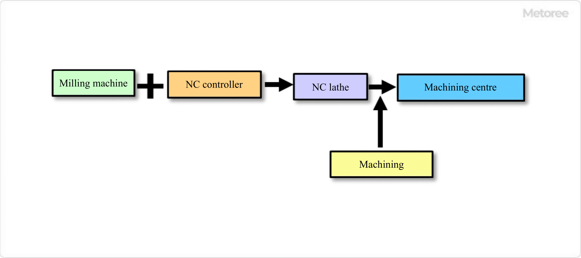
Since these machine tools were developed from NC milling machines, most of the machining operations that can be performed on NC Machining machines can also be performed on machining centers. Major applications include boring, milling, drilling, threading, reaming, grooving, and face machining required for industrial equipment. The machine is characterized by its ability to perform a wide variety of complex precision parts machining in sequence.

The above is a description of typical NC Machining applications, but NC Machining technology is also applied to various other machine tools, such as honing machines used in honing, a type of polishing process, electric discharge machines used in electrical discharge machining, and laser cutting machines used in laser machining.

Principle of NC Machining

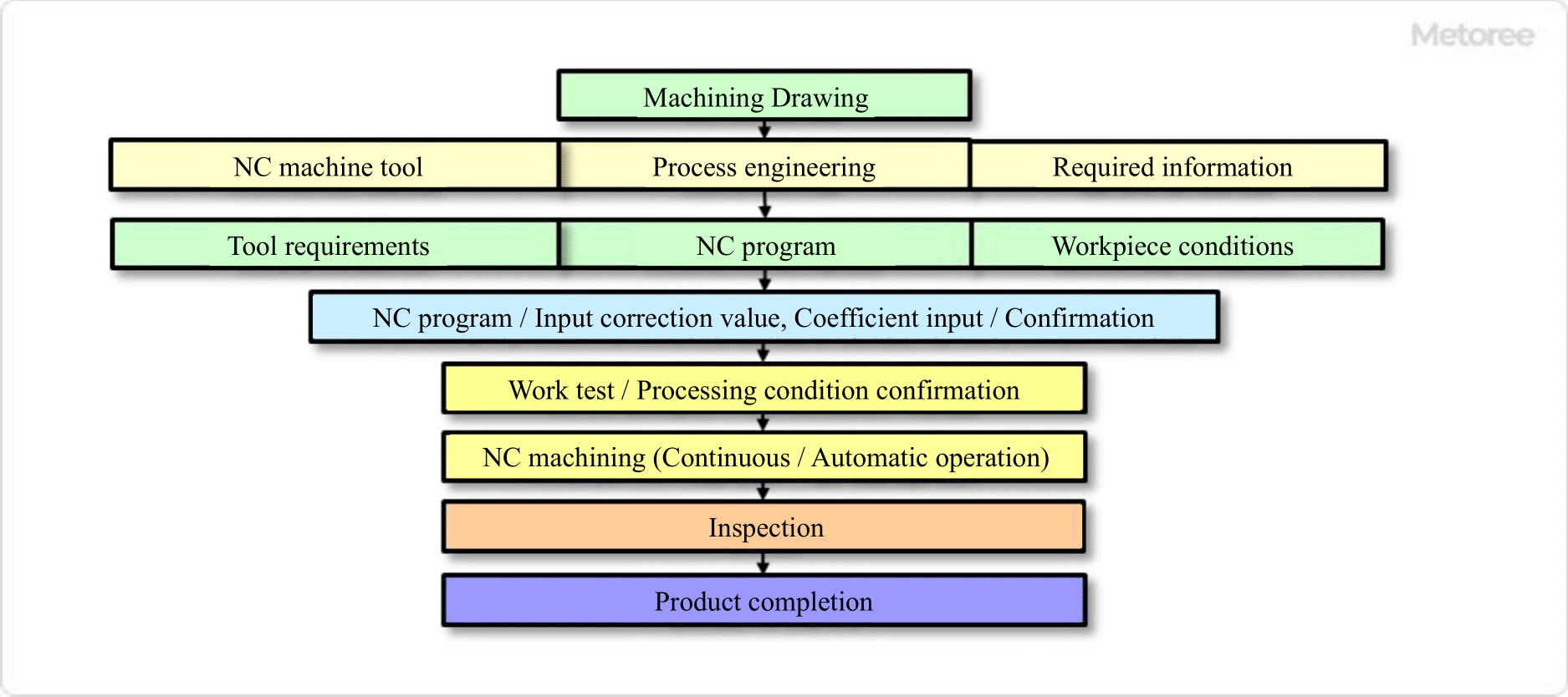
Figure 4. NC machining process

Figure 4. NC machining process

Every NC Machining machine is composed of an NC device (which sends NC programs to the lathe), an operation panel (where the operator gives various machining instructions to the NC device), and servo motors (which move the machining device according to the NC device’s instructions). This program is called an NC program and is used to control the machine tool.

This program is called an NC Machining program, which is a workpiece machining program based on CAD data.

Other Information on NC Machining

Advantages of NC Machining

High Quality
General-purpose machine tools are operated by operators, which may cause defective products due to operation errors or variations in dimensions and surface conditions due to skill levels, which may result in inconsistent quality. NC Machining, on the other hand, automatically controls machining based on numerical data, resulting in higher machining accuracy, less variation, and more stable quality.

Mass Production and Lower Cost
General-purpose machine tools are operated manually by individual operators, which limits production volume. Furthermore, multiple machining centers can be operated at the same time, leading to higher productivity.

Another advantage is higher work efficiency, which reduces the loss of efficiency due to worker fatigue. Furthermore, it is also effective in terms of passing on skills, as even unskilled workers can perform machining to a certain level of precision.

Safety
Automated machining by NC Machining reduces the possibility of workplace accidents, such as workers being caught in the machine or injured by tools or knives. In addition, the machining operation area is enclosed by a cover or door, which improves worker safety.

2. disadvantages

Expensive Capital Investment
NC machine tools require a general-purpose machine tool, NC controller, peripheral equipment, software, etc., making the capital investment expensive at the time of introduction. Since general-purpose machine tools are more cost-effective for simple machining, it is important to plan for the future when introducing NC machine tools.

NC Program Creation, Quality Assurance, and Information Management
To create NC programs, it is necessary to train and secure engineers who have acquired programming knowledge. It is also important to verify that there are no problems with the program and ensure its quality.

Furthermore, since the program itself is intellectual property and a trade secret, it is essential to ensure information security.

Setup Time Is Necessary
Because setup work is required before machining, such as program loading, the operation time may be longer than that of general-purpose machine tools.

カテゴリー
category_usa

Vibration Testing Services

What Is a Vibration Testing Service?

Vibration testing services are tests to check whether a test sample malfunctions or not by daring to apply vibration to the product.

Products such as electronic components are often used in locations subject to vibration, which may cause loosening or cracking of screws. Therefore, vibration testing services are conducted to ensure that products operate properly, even in environments subject to vibration.

Uses of Vibration Testing Services

Vibration testing services are often used to evaluate the quality of products that are used in places where vibration can occur in order to confirm that vibration does not cause defects.

For example, when a car is running, each part of the car body is constantly vibrated by the engine. If the vibration is so severe that a part of the car malfunctions, the car itself may break down and personal safety may be compromised. Vibration testing is performed on parts of a product whose safety or performance is affected by vibration.

Principles of Vibration Testing Services

Vibration testing services evaluate both vertical and horizontal vibration of a product.

Vibration testing services are performed by placing a test sample on a shaker table and generating vibrations with a shaker. Vibration conditions vary, as each product is subjected to different vibrations.

カテゴリー
category_usa

Pressure Cookers

What Is a Pressure Cooker?

Pressure cookers are used to evaluate the humidity resistance of electronic products under conditions of 100°C or higher and high humidity.

Since the test is conducted under conditions that are hotter and more humid than the normal environment in which electronic products are placed, the water vapor pressure inside the test chamber is considerably higher than the water vapor partial pressure inside the test sample.

This allows moisture to penetrate into the test sample, an electronic product, for a shorter period and can be used as an accelerated test to confirm moisture resistance.

Applications of Pressure Cookers

Pressure cookers can be used to check the penetration of moisture into electronic products under high temperature and humidity conditions.

In many electronic products, the circuit board is covered with resin, etc. If water penetrates into electronic products under high humidity conditions, it may affect the insulation resistance characteristics and aluminum corrosion inside the product. Therefore, electronic products are required to have durability against humidity. Since accelerated testing for humidity stress is possible, it is often included as a test item when electronic components are shipped.

Principle of Pressure Cookers

Pressure cookers require special equipment because they must be set at temperatures above 100°C and high humidity.

First, the test conditions are created by setting the temperature, humidity, and pressure in a test chamber. The test sample is placed in the test chamber for a specified period, and then several items are checked, including insulation degradation of the printed wiring board.

Types of Pressure Cookers

1. Unsaturated Pressure Cookers

Unsaturated pressure cookers are conducted in an environment of 85% humidity. This is one of the environmental tests for electronic products, and its criteria are specified in international standards. 

2. Saturated Pressure Cookers

Saturated pressure cookers are conducted in an environment of 100% humidity. Since the humidity is higher than that of the unsaturated pressure cookers test, the water vapor pressure in the test sample can be extremely high, which accelerates the penetration of moisture and is therefore used as an acceleration test.

カテゴリー
category_usa

Absolute Pressure Gauges

What Is an Absolute Pressure Gauge?

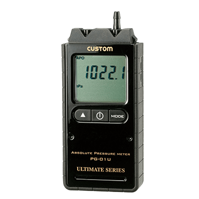
Absolute Pressure Gauges

Absolute pressure gauges are a type of pressure gauges that measures the pressure applied to an object.

There are two types of pressure gauges: those that measure “absolute pressure” and those that measure “gauge pressure,” and absolute pressure gauges, as the name suggests, can measure absolute pressure.

Normally, when measuring pressure, atmospheric pressure, which is always applied in daily life, is used as the zero standard and the difference from atmospheric pressure is measured as “gauge pressure.” Absolute pressure gauges, however, measure pressure with a vacuum state as the zero standard and obtain a value different from gauge pressure.

Uses of Absolute Pressure Gauges

The relationship between absolute pressure and gauge pressure is as follows:

Absolute pressure – Atmospheric pressure = Gauge Pressure

Atmospheric pressure is the pressure that is always applied in everyday life and is the weight of air. Atmospheric pressure is highest at sea level and decreases as elevation increases.

Absolute pressure gauges are used to measure the pressure inside vacuum pumps and sealed spaces, because they can measure the pressure applied to an object itself without taking into account the atmospheric pressure values that vary from place to place.

Principle of Absolute Pressure Gauges

Basically, when measuring pressure, the side to which the pressure to be measured is applied is the base side, and the difference from the pressure on the back side is quantified. Although the measurement method is the same, there is a difference in the detection method used to detect each pressure.

Gauge pressure gauges measure the difference in pressure from atmospheric pressure, so the part that detects the pressure on the rear side is either open and uses the atmospheric pressure in place, or it detects atmospheric pressure in a pattern that encloses atmospheric pressure and produces a differential pressure.

Absolute pressure gauges, on the other hand, detect vacuum pressure by using a vacuum chamber for the part that detects pressure on the rear side and outputs the difference between the vacuum pressure and the absolute pressure.

In the past, pressure gauges were often displayed in memory, but recently, more and more are being displayed digitally to measure pressure with higher accuracy.

カテゴリー
category_usa

Compound Gauges

What Is a Compound Gauge?

Compound gauges are pressure gauges that can measure both positive and negative pressures.

In addition to compound gauges, there are also ordinary pressure gauges and vacuum gauges, each of which can measure different pressures. Commonly used pressure gauges can measure only positive pressure, while vacuum gauges can measure only negative pressure.

Compound gauges can measure both positive and negative pressure, but the range of pressure they can measure is limited to -0.1 to 0.4 MPaG.

Applications of Compound Gauges

Compound gauges are used in places where the operating conditions of a machine can result in either positive or negative pressure.

Examples include places where pumps are used to draw gases or liquids, or equipment that use steam for heat exchange. When pumps are used to draw in gases or liquids, the pressure inside the pump may be lower than atmospheric pressure, so it is better to use compound gauges.

Compound gauges are often used for industrial purposes, but they are also used in familiar places, such as installed in the water supply side piping of fire pump trucks.

Principle of Compound Gauges

When pressure is applied to compound gauges, the “Bourdon tube” inside the pressure gauge is deformed. The pressure applied is detected from the degree of deformation, and the pressure is measured by reflecting the detected value as it is.

When negative pressure is measured with a compound gauges, it is not possible to say that the negative pressure is accurately measured because it is indicated by detecting the deformation of the Bourdon tube in the opposite direction. If you want to know the exact value of negative pressure, it is better to use a vacuum gauge even if the negative pressure is very small.

In addition, an increasing number of compound gauges are nowadays digitally marked. Digital readings are easier to understand at a glance than scale readings, and the accuracy is so high that they can be used for inspections at public institutions.

カテゴリー
category_usa

Knife Sharpening Machinery

What Is Knife Sharpening Machinery?

Knife sharpening machinery is a machine that sharpens knives to maintain their sharpness.

Blades are made by finishing the metal tip at an angle to make it sharp. However, if the cutting edge becomes rounded or scratched through continued use, the sharpness of the blade will deteriorate. Knife sharpening machinery can make the cutting edge sharp again by shaving off the rounded edge.

Uses of Knife Sharpening Machinery

A kitchen knife is a typical blade. When the sharpness of a knife deteriorates, the sharpness is manually restored using a whetstone or a knife sharpener. Knife sharpening machinery is used in such cases, however, because it is difficult and time-consuming to sharpen larger and more complex shaped knives manually.

Since the grinder is operated electrically, it is easy to sharpen the blade by simply touching the blade tip to the grinder.

Principle of Knife Sharpening Machinery

Knife sharpening machinery is usually equipped with a grinding stone for sharpening blades and a tank that gradually supplies water to the grinding stone and blades. The blade is set at the angle at which it is to be sharpened, and the rotating grinding stone is brought into contact with the blade to sharpen and sharpen its edge. Water is also supplied constantly to prevent heat generated by the rotation of the grinding wheel and friction between the blade and the grinding wheel, making the machine relatively easy to use.

There are several types of knife sharpening machinery, depending on the type of grinding wheel and the method of operation used to move the grinding wheel.

The three most common types of grinding wheels are silicon carbide abrasive, fused alumina abrasive, and diamond abrasive, and the blade material that can be sharpened depends on the type.

There are two ways to operate the grinding wheel: one is to rotate it with electric power and the other is to vibrate it with sound waves. The rotating type takes up a little space, so it is important to secure a space for it.