カテゴリー
category_fr

connecteur antidéflagrant

Qu’est-ce qu’un connecteur antidéflagrant ?

Les connecteurs antidéflagrants sont des connecteurs pour les connexions électriques utilisées dans des environnements explosifs ou dangereux.

Le terme “antidéflagrant” fait référence à une structure qui empêche les explosions ou les flammes. Les équipements antidéflagrants doivent être utilisés dans les usines qui manipulent des gaz explosifs ou des liquides inflammables ou volatils. Les connecteurs antidéflagrants sont conçus pour éviter les étincelles ou les fortes radiations électromagnétiques qui pourraient provoquer une explosion.

Des matériaux spéciaux sont utilisés pour garantir la robustesse et une grande durabilité dans les environnements explosifs. Les connecteurs antidéflagrants doivent respecter des normes et des critères de sécurité spécifiques. Les normes internationales comprennent ATEX (Europe), NEC (États-Unis) et IECEx (International).

Utilisations des connecteurs antidéflagrants

Les connecteurs antidéflagrants sont utilisés dans les usines chimiques, l’industrie minière et l’armée.

1. Industrie manufacturière

Ils sont souvent installés dans des environnements soumis à des gaz explosifs générés lors de la production de produits chimiques et pétroliers. Les connecteurs antidéflagrants assurent des connexions électriques sûres aux équipements électriques et aux appareils de mesure.

2. Industrie minière

Dans l’industrie minière, des gaz et des poussières explosifs peuvent être générés lors des opérations d’extraction et de raffinage dans les mines. Des connecteurs antidéflagrants sont donc nécessaires. Ils servent dans l’éclairage des mines, les systèmes de communication et les commandes de moteurs.

3. Installations militaires

Les installations militaires manipulent souvent des matières explosives. Les connecteurs antidéflagrants sont donc largement utilisés. Pour éviter les accidents et les incendies causés par des substances explosives, un haut niveau de sécurité est requis dans les connexions électriques et les systèmes de communication.

Principe des connecteurs antidéflagrants

Les connecteurs antidéflagrants sont dotés d’un boîtier étanche qui empêche la pénétration de gaz explosifs et de poussières provenant de l’extérieur. Le boîtier est souvent en acier inoxydable ou en d’autres alliages métalliques.

Ils comportent également des zones de contact pour la transmission des signaux électriques. Ils sont constitués de broches et de douilles métalliques et se caractérisent par la stabilité du signal et une faible résistance de contact. Les parties de contact des connecteurs antidéflagrants minimisent le risque d’explosion, par exemple en utilisant des espaces antidéflagrants.

Ils peuvent également être équipés de dispositifs de blindage pour éviter les interférences électromagnétiques externes et les effets électrostatiques. De plus, les câbles sont souvent mis à la terre au niveau des connecteurs et des connexions de câbles. Cela permet de contrôler les décharges électrostatiques et de réduire le risque d’explosion.

Pour éviter les étincelles et les décharges dues à des connexions incomplètes, des mécanismes de verrouillage sont souvent prévus. Si le connecteur n’est pas connecté correctement, le circuit électrique est interrompu, ce qui garantit la sécurité.

Types de connecteurs antidéflagrants

Les performances antidéflagrantes des connecteurs antidéflagrants sont spécifiées dans les normes nationales et internationales. Ils sont également classés de la zone 0 à la zone 2 par ordre de danger croissant en fonction du type et de la quantité de matières dangereuses manipulées. La construction antidéflagrante requise pour chaque zone est spécifiée.

Les quatre principaux connecteurs antidéflagrants utilisés sont : les connecteurs antidéflagrants à sécurité intrinsèque, les connecteurs antidéflagrants contre la pression, les connecteurs antidéflagrants contre la pression interne et les connecteurs antidéflagrants à sécurité accrue.

1. Connecteurs antidéflagrants à sécurité intrinsèque (Symbole i)

Cette structure ne constitue pas un point d’ignition pour des espaces explosifs en cas d’étincelles ou de températures élevées pendant le fonctionnement normal et les dysfonctionnements.

Dans les zones 0, les équipements difficiles à rendre intrinsèquement sûrs, tels que les panneaux de commande, sont souvent installés en dehors de la zone antidéflagrante. Des connecteurs antidéflagrants sont utilisés pour les connexions électriques à partir de l’armoire de commande.

2. Connecteurs antidéflagrants contre la pression externe (Symbole d)

Il s’agit d’une structure étanche qui résiste à la pression d’une explosion externe sans risque d’inflammation supplémentaire. Des boîtiers métalliques robustes sont utilisés et ils sont classés zone 1.

3. Connecteurs antidéflagrants contre la pression interne (Symbole f)

Une structure dans laquelle un gaz protecteur est scellé à l’intérieur pour éliminer le risque d’inflammation. L’azote est utilisé comme gaz de stockage.

4. Connecteurs antidéflagrants à sécurité renforcée (Symbole e)

Une structure avec des mesures de sécurité pour éviter les étincelles, les arcs électriques et les températures élevées. Ils peuvent être considérés comme étant de zone 3.

カテゴリー
category_usa

Lux Logger

What Is a Lux Meter?

A lux meter is a device that measures illuminance (a measure of brightness) and outputs it as numerical data to a computer or other device.

When work is performed in a set area, the brightness of the surrounding area is important.

Human evaluation is not suitable for assessing brightness. This is because the human eye is accustomed to the environment, there are large individual differences, and numerical data cannot be obtained.

Since lux meters can measure brightness as objective and quantitative data called “illuminance,” they can solve the problem of human evaluation.

In addition, since lux meters have a function to send data to a PC, there is no need for a human to manually record the data.

Uses of Lux Meters

Lux meters are widely used in situations where the brightness of the environment is objectively evaluated.

Illuminance measurement is essential in environments such as factories and laboratories, where illuminance is more important for business than in general offices.

Since it is troublesome to manually input the measured illuminance into a personal computer for analysis, it is common to use lux meters so that they can be automatically transmitted to a personal computer.

Principle of Lux Meters

The unit of illuminance measured by lux meters is lux, also known as lx. It is calculated by dividing the luminous flux (in lm) by the area (in m2).

The definition of luminous flux is “the brightness of light passing through a surface”. However, since luminous flux is brighter when the area is larger, illuminance is calculated by dividing the luminous flux by the area of that surface.

Since the required brightness is the same in both large and small offices, it makes sense to use illuminance instead of luminous flux as a measure of brightness.

White light is a composite of light distributed over a wavelength of approximately 400 nm (blue-violet) to 700 nm (red). The human eye is sensitive to different wavelengths, with a peak distribution at about 555 nm (green).

A lux meter passes the incident light through a filter that mimics human sensitivity and receives the light with a photodiode. The photodiode is an element that converts the received light into an electrical signal.

The electrical signal converted from light by the photodiode is measured to obtain the illuminance. The obtained illuminance is sent to a PC with a log function, allowing analysis using software such as Excel.

カテゴリー
category_usa

Panel Cooler

What Is a Panel Cooler?

A panel cooler is a device used to cool electrical control panels and electronic equipment.

Electrical control panels are devices used to control machines and processes, and there is a risk of internal equipment malfunctioning due to high temperatures or overheating. Panel coolers are used to maintain the temperature inside such control panels within an appropriate range.

Many products use a heat exchanger or cooling system to exhaust the heat inside the control panel to the outside. Simpler products are also available that simply use a fan to draw in outside air. This ensures that the ambient temperature inside the control panel does not rise and that the temperature conditions necessary for equipment operation are maintained.

However, when installing a panel cooler, it is important to provide adequate space and ventilation. It is necessary to ensure that there are no obstructions around the cooler and that proper air flow is maintained to maximize the cooling effect.

Uses of Panel Coolers

Panel coolers are widely used in the following applications:

1. Manufacturing Industry

Panel coolers for industrial machinery are also important in the control panels of machines used in factories and manufacturing sites. These machines operate under high loads, and rising temperatures inside the control panels can be a problem.

Examples include the control panels of automobile assembly lines and metalworking machinery. Panel coolers ensure the stable operation and reliability of machines by maintaining the temperature inside the control panel within an appropriate range.

2. Buildings and Offices

Panel coolers are widely used in automatic control systems in buildings and facilities. These systems include elevators, heating and cooling systems, lighting controls, and security systems. Panel coolers can improve system efficiency and reliability by properly controlling the temperature inside the control panel.

3. Power Distribution

Power supply and distribution systems often require panel coolers as well. They are used inside control panels for power control and protection equipment in power generation, substations, and transmission facilities. These control panels generate heat due to high power loads and power conversion.

Panel coolers for control panels can control the temperature inside the control panel to prevent overheating and functional degradation of the equipment. This ensures stability and reliability of power supply and distribution.

4. Telecommunications and Network Equipment

Panel coolers are important for control panels in telecommunication and network equipment such as telecommunication base stations and data centers. Because these devices require advanced processing capabilities, they are prone to generate heat and require appropriate cooling.

Panel coolers properly control the temperature inside the control panels of telecommunication and network equipment to ensure stable and reliable operation of the equipment. They are used particularly effectively in data centers to cool large numbers of servers and network equipment.

Principle of Panel Coolers

Panel coolers use a cooling principle to remove heat. Cooling principles often include forced convection cooling and cooling using heat exchangers. The cooling effect is achieved by forcibly circulating air using a fan.

Fans are used to exhaust the heat inside the control panel to the outside. Hot air in the control panel is sucked in by the fan and discharged to the outside, thereby lowering the temperature inside the control panel. Panel coolers for control panels may incorporate a heat exchanger.

The heat exchanger transfers heat from the hot air inside the control panel to the cooling medium, which then dissipates heat to the outside, causing the temperature inside the control panel to cool.

How to Select a Panel Cooler

When selecting a panel cooler, the following factors should be considered:

1. Cooling Capacity

The cooling capacity of a panel cooler should be selected based on the heat load in the control panel and environmental conditions. It is important to accurately evaluate the heat load in the control cabinet and select a cooler with appropriate cooling capacity.

Add up the heat generated by the CPU and other components installed in the control panel, and select a cooling capacity that will keep the temperature inside the control panel below the allowable temperature. In most cases, the allowable temperature of electronic components is about 40°C, so the cooler should be designed to keep the temperature below 40°C. In some cases, a fan with a large air volume is selected and used by turning it on and off with an in-panel thermo switch.

2. Atmosphere

Select equipment in consideration of the atmosphere around the control panel. If the control panel is installed in a location where the outside air is clean, use a fan for the control panel. In coastal areas, where corrosion due to salt damage is a concern, a panel cooler that circulates internal air is used.

3. Refrigerant

When selecting a control panel cooler with internal air circulation, attention should be paid to the type of refrigerant. In the past, many CFC gas coolers were used, but now many non-CFC coolers that use carbon dioxide and other gases are sold as alternatives.

4. Power Supply

The type of power supply should be selected. There are various types of single-phase power supplies and three-phase AC power supplies. Select a power supply that can be supplied after satisfying the cooling capacity.

カテゴリー
category_usa

Static Electricity Sensor

What Is a Static Electricity Sensor?

A static electricity sensor is a type of device that measures the amount of static electricity in an object to be measured, also called a surface potential measuring instrument.

It is a non-contact sensor that utilizes the phenomenon that an electric field with a strength proportional to the amount of charge is generated around a charged object.

Static electricity sensors can measure static electricity not only on metals, but also on all dielectric materials such as plastic, glass, and water. In addition to installed static electricity sensors, handheld static electricity sensors are also available to pinpoint the location to be measured.

Since static electricity sensors depend on the measurement distance, the displayed potential also changes when the measurement distance is changed. Therefore, for accurate measurements, it is recommended to fix the sensor at a set distance.

Uses of Static Electricity Sensors

Static electricity sensors are used in manufacturing lines in a variety of industries, including semiconductors, electrical equipment, automobiles, food, and pharmaceuticals.

When static electricity is generated in a production line, dust and other particles are attracted to and adhere to parts, posing the danger of dust adhering to and mixing with products, or parts repelling each other, causing problems that can lead to quality and yield problems.

For this reason, static electricity countermeasures are essential to prevent the generation of static electricity on the production line, and static electricity sensors are needed to accurately determine the amount of static electricity generated at various locations on the production line in order to implement static electricity countermeasures.

Principle of Static Electricity Sensors

Static electricity sensors generally consist of a sensor section containing a detection electrode and an amplifier section that converts the detected electric charge into a voltage signal.

When a charged object approaches the sensor, the sensor part receives an electric field from the object and generates an induced charge proportional to the strength of the electric field by electrostatic induction. In front of the sensing electrode is an oscillating electrode called a chopper, which periodically changes the electrostatic field strength.

At this time, the induced charge changes periodically as well, and an alternating current flows between the sensing electrode and ground. This current is impedance-converted in the amplifier section and extracted as an AC voltage signal to determine the charged potential of the object to be measured.

When using static electricity sensors, it is important to note that even if the amount of static electricity in the object to be measured is the same, if the electrostatic capacitance is different, the obtained charged voltage will change. For example, if the object to be measured is in contact with a metal, its capacitance will be higher than that of a single object, and the measured blackout potential will be converted to a lower value even if the amount of electrostatic charge remains constant.

カテゴリー
category_usa

Electrostatic Shoe

What Is an Electrostatic Shoe?

Electrostatic Shoes

ESD (Electrostatic Discharge) shoes are safety footwear used to prevent accidents caused by electrostatic discharge.

When people walk or do other activities, they are charged by electrostatic induction caused by friction between clothing and other objects.

This phenomenon means that unless some measures are taken, people are always in a dangerously charged state that can trigger ignition of flammable materials or electric shocks. To avoid this, it is simple and effective to wear ESD shoes that allow static electricity generated to escape from the soles to the floor so that it does not accumulate on the human body.

It is important to note that it is difficult to maintain the original performance of ESD shoes if the soles are worn out or coated, so a visual check before use is the first step to safety.

Uses of ESD Shoes

ESD shoes are used in three major ways.

The first is for use in places where static electricity may cause accidents or disasters such as explosions, fires, and electric shocks. Examples include: Various factories that handle flammable materials such as petroleum, chemical, painting, printing, etc.

The second is for use in locations where production disturbances such as damage or contamination of electronic elements caused by static electricity may occur. Examples include: electronics manufacturing plants.

The third is use under high voltage, such as inspection of high-voltage electric cables.
Since inspection of high-voltage electric cables must be performed without fail even in winter, safety shoes are designed for use in 0°C environments.

Principle of ESD Shoes

In order to maintain the human body at a safe level of electrification, the generated static electricity must escape to the floor within a few hundred milliseconds, and the charged potential of the human body must be suppressed to several 10V or less.

  • General ESD Shoes: 1.0 x 10^5 ≤ R ≤ 1.0 x 10^8 (1.0 x 10^5 ≤ R ≤ 1.0 x 10^9)
  • Special ESD Shoes: 1.0×10^5≦R≦1.0×10^7 (1.0×10^5≦R≦1.0×10^8)
  • Conductive Shoes: R<1.0×10^5 (R<1.0×10^5)
    *Measurement temperature: 23°C±2°C, values in parentheses are reference values under 0°C environment.

Furthermore, since humidity is also an important factor in the generation of static electricity, products that meet the criteria for use in dry conditions with lower values at three levels of humidity (12±2%, 25±3%, and 50±5%) are considered to be more stable ESD shoes.

Although it is difficult to explain the numerical value, it can be simply described as a very cost-effective safety shoe that releases static electricity generated in the human body instantly from the insole of the shoe → inner sole → conductive path of the sole → sole of the shoe → ground.

カテゴリー
category_usa

Insulated Crimp Sleeve

What Is an Insulated Crimp Sleeve?

Insulated Crimp Sleeves

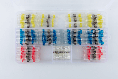
An insulated crimp sleeve is a crimp sleeve with an insulated surface. It is mainly used to connect wires at intermediate points.

The insulation coating electrically insulates the wires from other circuits and components, preventing electrical contact with the external environment. This prevents electrical shorts and leakage, and also ensures safety.

It also protects conductors from external factors such as vibration and chemicals, preventing damage and deterioration. It can also improve various performance characteristics, such as wear resistance.

However, it is important to install the sleeves correctly. Using a crimping tool, the sleeve must be securely fastened to the conductor. If not correctly installed, the insulating and protective effects are likely to be compromised.

Uses of Insulated Crimp Sleeves

Insulated crimp sleeves are used in a variety of industries. However, all of them are used for electrical wiring connections. They are not used for any other purpose.

They are generally used for repairing wiring. When wiring fails due to wire breakage, etc., it may be connected at an intermediate point for collection. By using insulated crimp sleeves for collection, it is possible to electrically connect the failed wiring while insulating it from the external environment by means of the insulated coating.

They may also be used when relocating equipment. When relocating industrial equipment that is in fixed use, it is not uncommon for the length of electrical wiring to be insufficient. By using insulated crimp sleeves, the same type of wiring can be spliced together.

They are used in a wide range of industries, from construction to the automotive industry. In buildings, they are used to connect in-wall wiring, while in automobiles they are used to connect harnesses.

Principle of Insulated Crimp Sleeves

Insulated crimp sleeves generally consist of two main parts: the insulation and the conductor. The insulation coating and the conductor.

1. Insulation Coating

The insulation coating is located on the outside of the sleeve and insulates and protects the conductor. Insulation performance is achieved by using an insulation coating such as vinyl chloride or nylon. Rubber and other materials may also be used.

It provides electrical insulation and cuts off electrical contact between the conductor and the external environment. This prevents electrical shorts and leakage currents.

It also provides physical protection and shields the conductor from the outside environment. The insulation coating serves to protect the conductor from elements such as friction and moisture.

2. Conductors

The conductor is the part of the sleeve that is inside and is responsible for transmitting electrical signals and power. It is generally made of metal and must be conductive and durable. Since adhesion to the wires is also important, soft materials such as oxygen-free copper are often used.

When making connections with wires, the use of crimping tools is recommended. Crimping with a crimping tool is called crimping. By using crimping pliers that are appropriate for the size of the joint of the crimped terminal, it is possible to make a tight fit and connection with normal power.

The wire is inserted into the crimped portion of the terminal with the insulation covering stripped away and the conductor exposed. Appropriate pressure is applied using a crimping tool to firmly secure the wire so that the conductors are in direct contact with each other. The wire connection section ensures a secure connection between the wire and the insulated crimp sleeve.

How to Select an Insulated Crimp Sleeve

When selecting an insulated crimp sleeve, it is important to consider the sleeve diameter, insulation material, and shape.

1. Sleeve Diameter

Sleeve diameter is the size of the conductor sleeve. Recommended wire diameters are listed in catalogs, etc. Generally, selection is based on the diameter of the wires to be connected. It is important to select a sleeve with a sufficient diameter even when multiple wires are to be crimped together.

2. Material

The material of the insulation coating should be selected from nylon or polyvinyl chloride. In general, nylon has a higher heat resistance temperature.

3. Shape

Various shapes of insulation sheaths are available. In general, straight sleeves are often selected. When wiring is detached, plug-in connection sleeves may be selected.

カテゴリー
category_usa

Single Axis Robot

What Is a Single Axis Robot?

A Single Axis Robot is a robot that can position itself in only one of the three directions of xyz.

They are incorporated into a wide variety of automated equipment and have become an indispensable part of automated machinery. Single Axis Robots have a simple structure consisting of a slider, motor, and ball screw.

They are used to transport linear workpieces, but are often used in combination with something else rather than as a stand-alone unit.

Uses of Single Axis Robots

Single Axis Robots are mainly used for workpiece transfer because of their linear motion. Specifically, they are used in a wide range of applications, including processing equipment, assembly equipment, conveyance equipment, packaging equipment, and inspection equipment. A similar device to Single Axis Robots is the RoboCylinder.

RoboCylinders are smaller and lighter than Single Axis Robots, but are more suited for conveyance. Single Axis Robots can only move horizontally in one direction, but by combining multiple units, they can be used for a variety of applications.

For example, they can be used for coating workpieces with resin or other materials, applying tape to the outer surface of circular workpieces, pushing and cutting workpieces by pressing them against them, and positioning jigs and tools.

Principle of Single Axis Robots

Single Axis Robots are mainly composed of a motor, a ball screw, and a slider.

1. Motor

The motor is the driving source of Single Axis Robots. Motors with controllable rotational speed, such as stepping motors and servo motors, are used. 

2. Ball Screw

The ball screw converts the rotational motion of the motor into linear motion. When the motor rotates, the ball screw rotates, and the amount of movement of the Single Axis Robot is determined by the amount of rotation of the ball screw.

3. Slider

The ball screw performs linear motion in one direction, but is not strong enough to resist the other two directions. For this reason, Single Axis Robots are equipped with a built-in slider. The slider guarantees the linear motion of the ball screw.

4. Controller

Single Axis Robots are operated via a controller. The controller is equipped with a connector for communication with a host controller, which may be a handy terminal or a PLC (Programmable Logic Controller).

Power is supplied directly to the controller, and data is exchanged mainly through the PLC. It can also be operated from a touch panel or other devices.

Other Information on Single Axis Robots

1. The Difference Between Single Axis Robots and Robocylinders

Both Single Axis Robots and RoboCylinders are high-precision electric actuators with motors, ball screws, and sliders. In other words, both have the same structure. However, in most cases, the price of a RoboCylinder is much lower than the price of a Single Axis Robot. This price difference is caused by the difference in the purpose of use.

Single Axis Robots are designed to perform “high-speed, high-precision, long-distance transfer of heavy objects. Therefore, “high rigidity,” “long stroke,” “high upper limit of transfer weight and positioning accuracy,” and “high maximum operating speed” are the characteristics of Single Axis Robots compared to RoboCylinders.

On the other hand, RoboCylinder is designed to “transport lightweight objects over short distances at a certain speed and accuracy. Compared to Single Axis Robots, Robocylinders are smaller in size and can be used as replacements for air cylinders.

Thus, Single Axis Robots and RoboCylinders have similar structures. However, by appropriately using Single Axis Robots and RoboCylinders in consideration of the type of motion to be performed on the workpiece and the level of quality required, the overall cost of the equipment can be reduced and the size of the equipment can be downsized.

2. 2-Axis Robot

A 2-axis robot is a robot that has two axes of motion. It is sometimes called a Cartesian robot. A Single Axis Robot can be converted into a 2-axis robot by adding one more axis to it. Therefore, it is possible to make your own 2-axis robot by adding one more axis to your Single Axis Robot without purchasing a commercial product.

For example, a slider of a Single Axis Robot dedicated to conveyance is attached to a pillar, and an air cylinder or a RoboCylinder is attached to the pillar. Controlled by the same controller, the robot can slide at any timing and push a workpiece out with the cylinder.

カテゴリー
category_usa

Electron Beam Lithography System

What Is an Electron Beam Lithography System?

Electron beam lithography systems are used to draw circuit patterns for LSI (large-scale integration) circuits.

Electronic devices such as cell phones and PCs contain semiconductor electronic circuit components called LSI.

After designing an LSI circuit, the circuit pattern must be burned onto a reticle (equivalent to film in silver halide photography) with an electron beam.

At this time, dimensional and positional errors must be kept within 2 to 5 nm.

The electron beam lithography system is used to burn the circuit pattern onto the reticle with this accuracy.

Uses of Electron Beam Lithography Systems

Electron beam lithography systems are used in the baking process of ultra-fine circuits used in LSIs.

LSI is an essential component of electronic devices. For example, LSIs are used as components in cell phones, PCs, game consoles, cameras, and other devices.

LSI designs change depending on the application, and there are LSIs suitable for various fields, such as communication devices, power supplies, acoustic processing, image processing, sensors, and AI.

In order to accommodate a wide range of LSI design patterns, circuit patterns designed by CAD (computer aided design) are burned onto reticles using an electron beam lithography system.

Principle of Electron Beam Lithography Systems

The LSI process is largely divided into design, front-end process, and back-end process.

Circuit patterns are drawn on reticles in the design stage, highly integrated electronic circuits are formed on silicon wafers in the front-end process, and semiconductors are cut from the wafers, fixed in place, and sealed in the back-end process.

In the design stage, the fine circuit pattern of the LSI is conventionally burned onto the reticle by optical transfer, similar to silver halide photography.

However, visible light has a wavelength of approximately 400 nm to 700 nm, so circuits finer than the wavelength of light cannot be burned onto the reticle.

As LSIs have become larger and larger over time, the subject of research was how to concentrate numerous circuits on a small LSI.

This is where the electron beam came in.

The wavelength of an electron beam is 0.012 nm at an acceleration voltage of 10 kV, so it can draw much finer circuit patterns than light.

However, to draw highly detailed circuit patterns, a high-precision electron beam lithography system is required.

The electron beam lithography system was developed for this purpose.

There are two types of electron beam lithography systems: the raster scanning system (which arranges “dots” like pixels on a TV) and the vector scanning system (which fills in shapes such as circles and rectangles).

This electron beam lithography system enables the drawing of high-definition circuit patterns on reticles.

カテゴリー
category_usa

Electromagnetic Field Analysis Software

What Is Electromagnetic Field Simulation Software

Electromagnetic Field Analysis Software

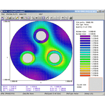
Electromagnetic field simulation software is software created for solving the fundamental equations governing electromagnetic phenomena. These equations are called Maxwell’s equations.

These days, rather than solving them analytically, it often means solving them with specific physical properties and boundary conditions using numerical solution methods, such as the finite difference time domain method or the finite element method.

Electromagnetic field simulation software includes electrostatic field analysis and electromagnetic field analysis, which deal with electric fields that do not fluctuate with time, and has a variety of applications such as microwave ovens, antennas, and wireless power transmission, not to mention electric motors such as DC motors.

Uses of Electromagnetic Field Simulation Software

Electromagnetic field simulation software is used to study how electromagnetic waves and magnetic forces affect objects. They are used in a wide range of industries, including automotive, space, and defense, but are especially common in manufacturing industries such as electrical and electronic equipment, where it is often used in the design process.

Electromagnetic field simulation software is performed on parts or devices that are subject to electromagnetic waves or magnetic forces, such as supercomputers, laptop computers, microwave ovens, antennas, motors, speakers, and many others.

Characteristics of Electromagnetic Field Simulation Software

The electric and magnetic fields together are called the electromagnetic field, which is created by an electric charge. When a charge is stationary, only an electric field is created, but when the charge moves and an electric current flows, a magnetic field is generated in addition to the electric field. Thus, the electric and magnetic fields are closely related, and Maxwell’s equations express this relationship. Electromagnetic field simulation software is a simulation based on Maxwell’s equations.

There are two major analysis methods: one is the time-domain analysis method, and the other is the frequency-domain analysis method.

The time-domain analysis methods include the finite-difference time-domain method and the transmission line method, while the frequency-domain analysis methods include the finite element method and moments.

The ultimate goal of electromagnetic field simulation software is to know the voltage and current distribution in a circuit or device, or the electromagnetic field near the device or radiated to a distant place. To accomplish this, the model must be created so that results can be obtained in a realistic amount of time, and the analysis must be performed under appropriate computational conditions.

カテゴリー
category_de

Sauerstoffsensor

Was ist ein Sauerstoffsensor?

Sauerstoffsensoren sind Sensoren zur Messung der Sauerstoffkonzentration in der Atmosphäre eines Messraums.

In einem isolierten, geschlossenen Raum ist es äußerst wichtig, die Sauerstoffkonzentration zu messen, um die Lebensaktivitäten aufrechtzuerhalten. Sauerstoffsensoren spielen bei dieser Messung der Sauerstoffkonzentration eine wichtige Rolle.

Wenn die Sauerstoffkonzentration unter 15 % fällt, haben Menschen Atembeschwerden, unter 7 % sind die Gehirnfunktionen beeinträchtigt und unter 4 % tritt der Tod ein. Sauerstoffsensoren werden in verschiedenen wissenschaftlichen und industriellen Bereichen benötigt und es wurde eine breite Palette von Sauerstoffkonzentrationsmessbedingungen und -systemen entwickelt, um den Anforderungen dieser Bereiche gerecht zu werden.

Ein typischer Sensor ist der Zirkoniumdioxid-Sensor. Zirkoniumdioxid-Sensoren werden auch für die Produktkontrolle in der Halbleiterherstellung, zur Energieeinsparung in Kraftfahrzeugen usw. sowie für die Abgasreinigung verwendet.

Anwendungen von Sauerstoffsensoren

Die Messung der Sauerstoffkonzentration hat zwei Hauptaufgaben: erstens die Erkennung und Überwachung zur Vermeidung von Sauerstoffmangel, was Menschenleben retten kann und zweitens die Kontrolle der Sauerstoffkonzentration, z. B. bei der Herstellung von Industrieprodukten.

1. Prävention von Säuremangel

Beispiele für Anwendungen zur Vorbeugung von Sauerstoffmangel sind das Sicherheitsmanagement im Hoch- und Tiefbau, z. B. in Tunneln und unterirdischen Bauwerken, sowie im medizinischen Bereich, z. B. beim Management der Sauerstoffinhalation und der hyperbaren Reanimation. Die Produkte für diese Anwendungen können tragbar sein oder an der Wand montiert werden.

2. Kontrolle der Sauerstoffkonzentration

Die Prozesskontrolle bei der Herstellung von Industrieprodukten wird in der chemischen Industrie, in der Keramik- und Metallindustrie eingesetzt. Eine Besonderheit bei der Herstellung von Industrieprodukten ist, dass sie bei Wärmebehandlungsprozessen häufig in Hochtemperaturumgebungen eingesetzt werden.

Ein bekanntes Beispiel aus dem täglichen Leben ist die Verwendung in Auto- und Motorradmotoren. Indem sie die Sauerstoffkonzentration in den Abgasen ermitteln, tragen sie zur Anpassung der Kraftstoffkonzentration bei.

Funktionsweise der Sauerstoffsensoren

Zu den Messprinzipien von Sauerstoffsensoren gehören der galvanische Batterietyp, der Zirkoniumdioxid-Einzelelektrolyttyp, der magnetische Typ und der wellenlängenabstimmbare Halbleiterlaserspektroskopietyp.

1. Typ der galvanischen Zelle

Der galvanische Batterietyp hat eine einfache Struktur und wird in tragbaren Sauerstoffmessgeräten verwendet. Er besteht aus Gold- und Bleielektroden, einer Harzmembran und einem Elektrolyten und verwendet einen Mechanismus, bei dem ein elektrischer Strom in Abhängigkeit von der Sauerstoffkonzentration erzeugt wird, wenn Sauerstoff die Membran durchdringt und sich im Elektrolyten auflöst.

2. Individuelles Elektrolytsystem aus Zirkoniumdioxid

Bei der Einzelelektrolytmethode mit Zirkoniumdioxid wird Zirkoniumdioxid als fester Elektrolyt verwendet. Es kann negative Sauerstoffionen (O2) in festem Zustand leiten und die Ionen werden von einem Gas mit hoher Sauerstoffkonzentration (Seite mit hohem O2-Druck) in eine Atmosphäre mit niedriger Sauerstoffkonzentration (Seite mit niedrigem O2-Druck) geleitet.

In einem Sauerstoffsensor mit Zirkoniumdioxid-Elektrolyt sind auf der O2-Hochdruckseite bzw. der O2-Niederdruckseite Elektroden installiert, die elektrisch miteinander verbunden sind: Wenn O2 versucht, das Zirkoniumdioxid als negative Ionen zu durchdringen, werden Elektronen an der Elektrode auf der O2-Hochdruckseite eingefangen und zu negativen Ionen, während auf der O2-Niederdruckseite Elektronen eingefangen und zu negativen Ionen werden. Auf der Seite des niedrigen O2-Drucks werden Elektronen aus dem übertragenen O2 aufgenommen.

Die Beziehung ist genau wie die zwischen der positiven und der negativen Elektrode einer Batterie: Die auf der Seite des niedrigen O2-Drucks (negative Elektrode) freigesetzten Elektronen fließen in die Seite des hohen O2-Drucks (positive Elektrode) zurück. Die elektromotorische Kraft, die zwischen den Elektroden erzeugt wird, kann zur Bestimmung des Sauerstoffpartialdrucks an jeder Elektrode verwendet werden und zwar mit Hilfe einer Beziehung, die als Nernst-Gleichung bekannt ist:

E= (RT/4F) – 1n (PA/PB)

wobei R die Gaskonstante, T die Temperatur, F die Faraday-Konstante und PA und PB die Sauerstoffpartialdrücke auf der Seite des hohen bzw. niedrigen O2-Drucks sind. Die Temperatur wird mit einem im Zirkoniumdioxid eingebauten Thermoelement gemessen und PA basiert auf dem Sauerstoffpartialdruck in normaler Atmosphäre.

Weitere Informationen zu Sauerstoffsensoren

Verschlechterung von Sauerstoffsensoren

Sauerstoffsensoren aus Zirkoniumdioxid, die in industriellen Fertigungsprozessen eingesetzt werden, sind einer Verschlechterung unterworfen. Sie werden in Umgebungen mit hohen Temperaturen eingesetzt und verschiedene Gase können die Zirkoniumdioxidzelle ebenfalls beschädigen oder beeinträchtigen. Reduzierende Gase wie Halogene sind ein weiterer Faktor, der zu einer Verschlechterung führen kann.

In Kraftfahrzeugen kann ein beschädigter oder ausgefallener Sauerstoffsensor zu einem Anstieg der Giftstoffe in den Abgasen führen. Auch der Kraftstoffverbrauch kann sich verschlechtern, wenn der Kraftstoff stärker konzentriert ist als nötig; wenn die O2-Sonde beschädigt ist, muss das Teil von einem Händler oder einer Werkstatt ausgetauscht werden.