カテゴリー
category_usa

Device Server

What Is a Device Server?

A device server enables the connection of non-networkable devices to a network via serial interfaces or USB ports. This is essential for devices like older printers and scanners, which use RS-232C or USB connections and cannot directly connect to a network due to differing communication protocols. A device server acts as a bridge, converting these protocols to enable network connectivity.

This connectivity allows a single device to be accessible from multiple PCs, enhancing usability and flexibility.

Uses of Device Servers

Device servers are pivotal in networking devices that lack inherent network capabilities. By doing so, equipment such as legacy printers and scanners become accessible from multiple computers. Additionally, device servers facilitate the remote operation of computers via peripherals like keyboards and mice, overcoming the limitations imposed by physical proximity and cable length. Some device servers also support Internet connectivity, enabling the creation of large-scale systems and remote monitoring.

Principle of Device Servers

Device servers convert the communication method of serial devices to be compatible with Ethernet interfaces. This conversion can occur in three modes:

1. Real Com Mode

Creates a virtual COM port on the host computer, enabling data transfer and operational control through serial port line signals.

2. Socket Mode

Facilitates access to serial device servers on a TCP/IP network via standard sockets API, eliminating the need for additional drivers.

3. Port Sharing Mode

Allows multiple host computers to share a single device server’s port, enabling them to receive data from the same serial device concurrently.

Types of Device Servers

The choice of device server depends on the specific networking needs of USB or serial devices:

1. Embedded Device Server

These compact servers are integrated into devices, offering basic networking capabilities for small devices.

2. Serial Device Server

Suitable for networking devices with serial interfaces, often used in industrial settings for data collection and device control.

3. USB Device Server

Enables networking of USB devices within a small network, supporting high-speed data transfer for applications like USB audio and web cameras.

4. Internet Device Server

These servers support Internet connectivity for remote monitoring and management systems, offering a cost-effective solution without the need for dedicated lines.

カテゴリー
category_usa

Nickel-Metal Hydride Battery

What Is a Nickel Metal Hydride Battery?

Nickel Metal Hydride Batteries

A nickel metal hydride battery is a type of rechargeable battery that can be charged and discharged, using a hydrogen storage alloy for the negative electrode and nickel hydroxide for the positive electrode.

Nickel metal hydride batteries are expensive because they use a hydrogen storage alloy instead of cadmium, but can be charged and discharged using a large current and have a large capacity per unit mass.

In addition, compared to other rechargeable batteries, nickel-metal hydride batteries have a relatively small memory effect (the voltage drop that occurs during discharge when batteries are repeatedly recharged without being fully discharged), and can be used repeatedly without performance degradation.

Uses of Nickel Metal Hydride Batteries

Nickel metal hydride batteries are used to take advantage of their high performance and long life, and are used in automotive batteries, notebook PCs, dry cell batteries, and other applications requiring high output and reliability.

In recent years, lithium-ion batteries, which do not have memory effect or self-discharge and have a larger capacity per unit mass and higher operating voltage, have come to be used.

Principles of Nickel Metal Hydride Batteries

1. Composition of Nickel Metal Hydride Battery

Nickel metal hydride batteries consist of electrodes (positive electrode: nickel oxyhydroxide, negative electrode: hydrogen storage alloy), a separator made of olefin nonwoven fabric, and potassium hydroxide solution as electrolyte. In the case of a dry cell, the structure wound around these components is contained in a can. 

2. Charge-Discharge Reaction of Nickel Metal Hydride Battery

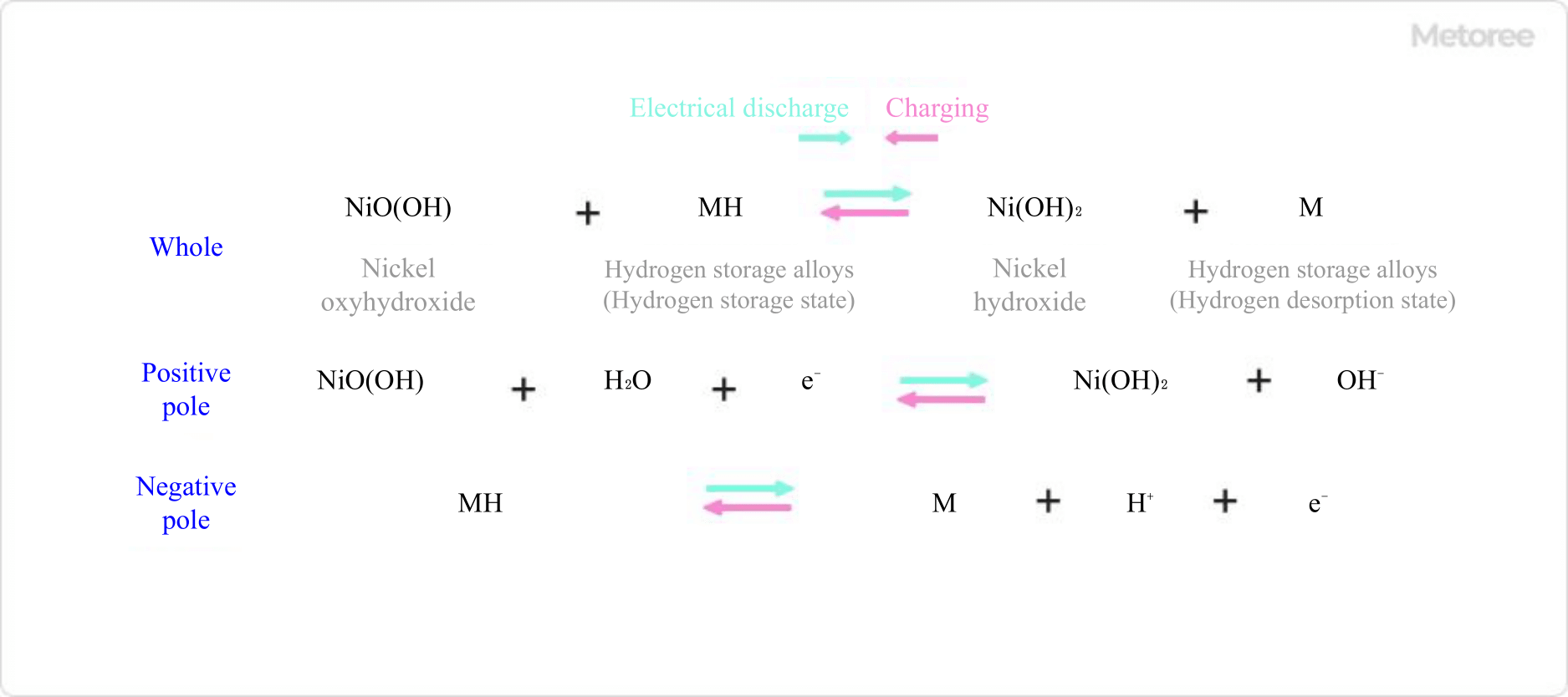
During discharge of a nickel metal hydride battery, at the positive electrode, nickel oxyhydroxide receives electrons in the presence of water, producing nickel hydroxide and hydroxide ions. At the anode, hydrogen ions and electrons are released from the hydrogen storage alloy in the presence of hydroxide ions to produce water.

During discharge, the reaction proceeds in the opposite direction: at the cathode, hydroxide ions react with nickel hydroxide to produce nickel oxyhydroxide, which releases electrons. At the anode, hydrogen is adsorbed by supplying electrons.

Figure 1. Charge-discharge reaction equation of a nickel-metal hydride battery

Figure 1. Charge-discharge reaction equation of a nickel-metal hydride battery

The charging and discharging of a nickel metal hydride battery occurs through a simple reaction that involves the adsorption of hydrogen and the production of water. For example, lead-acid batteries used in automobile batteries are charged and discharged through a precipitation-dissolution reaction of the electrodes, so repeated charging and discharging inevitably results in deterioration of the electrodes. A nickel metal hydride battery has no such degradation mode and can be used semi-permanently as long as the electrode itself does not deteriorate, making it a battery with a long service life. 

3. Electrodes of Nickel Metal Hydride Battery

Co-alloys have been mainly used for the negative electrode in the past in order to achieve high capacity, but there has been a move toward Co-free electrodes mainly due to cost considerations. However, the use of Co-fewer alloys has been progressing, mainly due to cost considerations. As for the cathode, nickel oxyhydroxide in the charged state is highly conductive, but nickel hydroxide in the discharged state is an insulator, which causes problems such as loss of electron paths during discharge. For this reason, cobalt oxyhydroxide or other materials are added to give conductivity.

Other Information on Nickel Metal Hydride Batteries

Nickel Metal Hydride Battery Characteristics

1. Battery Characteristics
The nominal voltage of nickel metal hydride battery is 1.2V, which is the same as that of a nickel-cadmium battery. This is because the reactions used for charging and discharging are similar. Since the nominal voltage of lead-acid batteries is 2.0 V and the rated voltage of lithium-ion batteries is 3.7 V, they are relatively low voltage batteries. Since these batteries can easily carry a large current, they are used in equipment that requires high output, such as hybrid cars.

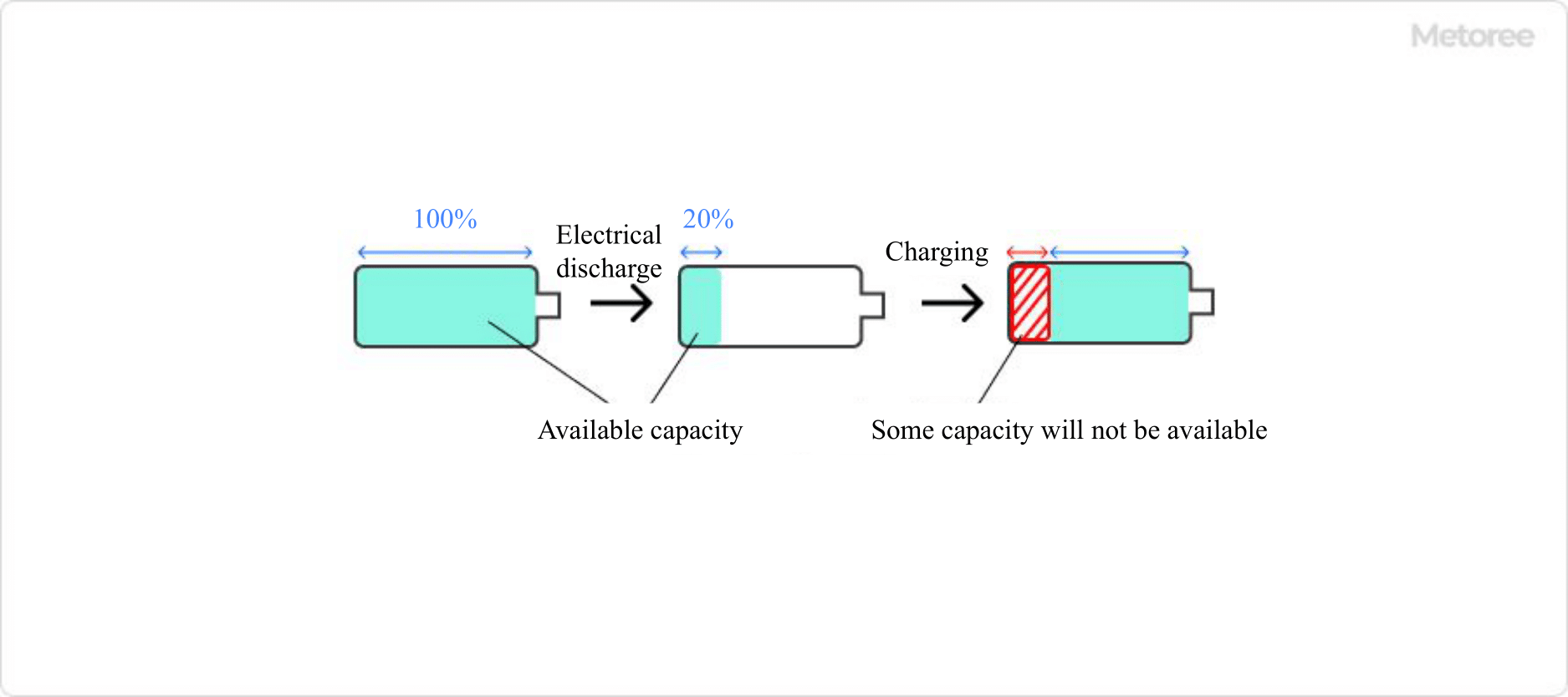
Nickel metal hydride batteries have a memory effect (the voltage of the battery drops as it is repeatedly recharged, resulting in a decrease in usable capacity and an inerting effect. Therefore, understanding the characteristics of the battery when using it will maximize its service life.

Figure 2. Memory effect

Figure 2. Memory effect

2. Safety
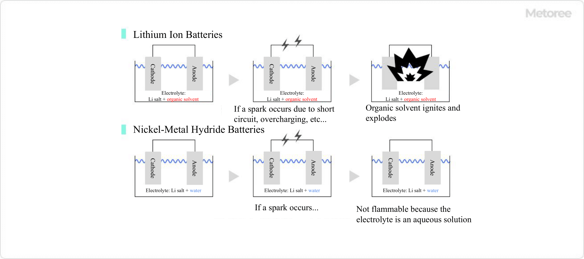
Basically, battery explosions and fires are caused by the ignition of organic solvents, which are electrolyte solvents, by sparks created by short circuits.

The electrolyte solvent in nickel metal hydride batteries is water, so even if a spark should occur, it will not ignite. Therefore, the current and voltage control mechanisms do not need to be designed as rigorously as in lithium-ion batteries, thus lowering the manufacturing cost. This low cost is one of the reasons why nickel metal hydride batteries are still widely used in industry.

Figure 3. Comparison of lithium-ion and nickel-metal hydride batteries

Figure 3. Comparison of lithium-ion and nickel-metal hydride batteries

3. Environmental Impact
Lithium-ion batteries, lead-acid batteries, and nickel-cadmium batteries contain hazardous substances with a high environmental impact (e.g., cadmium in nickel-cadmium batteries is a causative agent of Itai-itai disease, one of the four major pollution diseases). The electrolyte is also an environmentally friendly storage battery because it does not use organic solvents.

カテゴリー
category_usa

Halogen Lamps

What Is a Halogen Lamp?

A halogen lamp is a type of incandescent lamp that contains trace amounts of halogen elements (iodine, bromine, etc.) in addition to inert gases such as nitrogen and argon.

Halogen lamps emit light in the same way as ordinary incandescent lamps, by passing electricity through a filament inside the bulb. The filament is a thin, thread-like metal wire, most often made of tungsten, which has the highest melting point of all metals (3,422°C).

Uses of Halogen Lamps

1. Lighting

Halogen lamps are used for spotlighting on product shelves, floodlighting, car headlights, studio and stage lighting, and other applications because of their compact size, high luminance, easily adjustable light distribution (light spread), and good color rendering properties (colors are close to those seen in sunlight). However, with the spread of LED light sources, opportunities for use in lighting applications are decreasing.

2. Projectors

Halogen lamps have been used as light sources for OHPs and slide projectors used in schools, etc. Today, LED and laser light sources are becoming the mainstream.

3. Light Source for Spectroscopic Analysis

Light sources for spectroscopic analysis are used because they have a constant brightness over a wide range of wavelengths and little fluctuation in intensity over time.

4. Heater

The fact that the majority of the energy radiated is infrared tells us that halogen lamps as light sources are inefficient but excellent heaters. Therefore, halogen lamps have applications in a variety of situations requiring localized heating, such as heat retention, heat treatment, drying, and high-temperature molding of food and materials, in addition to localized heating indoors and outdoors.

Principle of Halogen Lamps

The filament temperature of ordinary incandescent lamps ranges from 1,500 to 3,000°C, while that of halogen lamps is usually as high as 2,500 to 3,000°C, with special ones reaching as high as 3,300°C. Therefore, a small amount of tungsten is constantly evaporating on the surface of the filament.
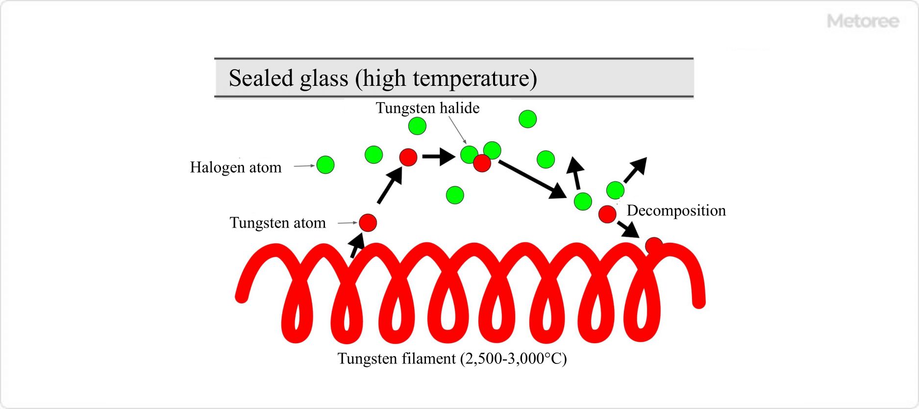
Figure 1. Halogen cycle

Figure 1. Halogen Cycle

To suppress the blackening phenomenon, halogen lamps contain a small amount of halogen elements along with inert gas in the bulb. In this way, if conditions such as temperature and materials are appropriate, the blackening phenomenon will not occur due to the halogen cycle that occurs in the lamp.

The halogen cycle is a phenomenon that occurs in the following manner.

  1. Tungsten atoms evaporate and diffuse from the hot filament during lighting.
  2. Halogen gas reacts with the evaporated tungsten to form tungsten halide.
  3. If the glass wall is hot enough (>170°C for iodine halogen), tungsten halide does not adhere to the glass wall.
  4. When the tungsten halide moves near the hot filament, it decomposes and the tungsten atoms return to the filament.

The halogen cycle prevents filament wear and tungsten-induced blackening of the glass inner wall.

Structure of Halogen Lamps
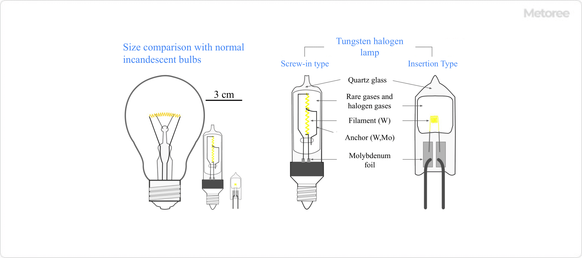
Figure 2. Incandescent and halogen lamps

Figure 2. Incandescent and Halogen Lamps

To achieve a halogen cycle, the encapsulated glass must be kept at a high temperature. When iodine is used as a halogen gas, the glass temperature must be 170°C or higher, and when bromine is used, the glass temperature must be 250°C or higher.

Therefore, quartz glass, which can withstand high temperatures, is usually used, and molybdenum foil is used to electrically connect the inside and outside of the halogen bulb so that the inside remains airtight even at high temperatures.

Other Information on Halogen Lamps

1. Disadvantages of Incandescent Bulbs

In ordinary incandescent bulbs, blackening occurs when evaporated tungsten adheres to the inner wall of the bulb’s glass. As the filament wears out, the luminous efficiency inevitably decreases.

This blackening phenomenon is an obstacle, making it difficult to miniaturize incandescent bulbs with high power consumption or to raise the filament temperature to higher levels to increase brightness and color temperature.

2. Characteristics of Light Emitted From Halogen Lamps
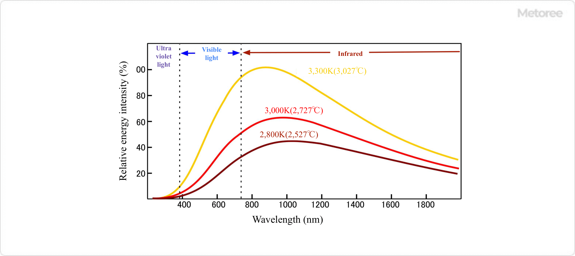
Figure 3. Filament temperature and intensity distribution of emission spectrum

Figure 3. Filament Temperature and Intensity Distribution of Emission Spectrum

The light spectrum emitted from a halogen lamp is almost identical to the blackbody radiation spectrum, which corresponds to the temperature of the filament. Because the temperature of the filament is lower than that of the sun, the emitted light contains almost no ultraviolet light, and its visible light portion has a slightly higher red component, resulting in a warm white light appearance.

The peak of the radiation is in the near-infrared region with wavelengths of 900 to 1,000 nm, and the majority of the radiation is in the visible to near-infrared region with wavelengths of 500 to 3,000 nm.

3. Advantages of Halogen Lamps

Compared to ordinary incandescent lamps, halogen lamps allow a smaller distance between the filament and the encapsulated glass. Also, the temperature of the filament can be higher, which offers various advantages.

  • Because of their small size, transportation costs can be significantly reduced.
  • Since the blackening phenomenon does not occur, there is almost no decrease in brightness until the end of the life of the product.
  • When used at the same filament temperature, the service life can be more than doubled.
  • Brightness can be increased by about 30% for the same life setting.
  • The use of quartz glass allows the surface temperature to be raised to approximately 900°C (twice as high).
  • Quartz glass has high thermal shock resistance and does not break even when heated to 900°C and placed in cold water.

4. Advantages of Halogen Lamps

  • Radiant Heat
    90% of the power consumption is radiant light that transfers energy directly to the object to be heated, making it suitable for rapid heating.
  • Low Heat Loss
    Radiant light reaches the object to be heated without being affected by air currents or air temperature, and since the radiation source (filament) is inside the glass tube, it is hardly affected by its surroundings.
  • Fast Start-Up
    Thermal radiation output reaches 90% of rated output within 1 second after energizing.
  • High Energy Density
    Small-sized halogen lamps can maintain a heat generation density of 100 w/cm2 or higher, which allows them to heat objects to 1500°C or higher.
  • High Thermal Shock Resistance
    The lamp will not be damaged even if water is splashed on it during use.
  • Metal Heating
    Wavelengths of visible light to near-infrared rays are easily absorbed by metals, making them suitable for heating metals.
  • Non-Contact Heating
    Does not contaminate the object being heated or the surrounding environment. Heating of a sample in a separate room is also possible through a glass window, etc.
  • Optical Control
    A reflective mirror or similar device can be used to precisely spot-heat a targeted area.
カテゴリー
category_usa

Neon Lamp

What Is a Neon Lamp?

Neon Lamps

A neon lamp is a lighting device that emits light when a glow discharge occurs in a glass tube filled with neon gas.

The lamp can emit light in a variety of colors by combining it with argon gas or by using a transparent tube and a fluorescent tube. Two electrodes are mounted inside the glass tube, and glow discharge is generated by externally controlled voltage.

In recent years, LEDs have become the mainstream lighting device, and neon lamps are used in the same way. The advantages of neon lamps include low power consumption, long life, no heat generation, and resistance to shock.

Uses of Neon Lamps

Neon lamps are lamps that emit light by filling a glass tube with neon gas. They are used for various effects and lighting, with entertainment district lighting being a typical example. In recent years, neon lamps have also been used for interior decoration.

Another application is the neon light-emitting detector. This detector uses the current from a neon tube that flows through a human being to the ground. It has the advantage of not requiring batteries, but it should be noted that it cannot be used when wearing insulated gloves, and there is a risk of electric shock.

The glass tube itself, which is filled with gas, can be processed by bending and stretching to be used as a text expression. By adjusting the thickness of the glass tube, the luminous intensity of the neon tube can be adjusted. Because of their low power consumption and long life, neon tubes are sometimes used for long periods as all-night lights, indicator lights (pilot lamps), and other lighting applications.

It was one of the most popular lighting devices until the advent of LEDs and is still used in the situations described above.

Structure of Neon Lamps

It consists of a glass tube with two electrodes made of iron or nickel and filled with neon gas at a low pressure of about 10~15 mmHg. The glass tube may be transparent or coated with fluorescent paint on the inside.

Neon gas emits red light in transparent tubes and pink or orange light in tubes coated with fluorescent paint.

Other Information on Neon Lamps

1. Neon Lamp Emission

When voltage is applied between the electrodes, the electrons between the electrodes are accelerated by the electric field and collide with neon gas, ionizing it into positively charged cations and electrons.

The resulting cations collide with the cathode, which emits secondary electrons. The emitted secondary electrons move to the anode, causing a large electric current to flow. This phenomenon is glow discharge.

This current (flow of secondary electrons) has enough energy to excite the neon atoms in the glass tube. As the excited atoms return to their ground state, they emit light with a wavelength corresponding to the energy difference between the energy bands. In the case of neon atoms, this light is observed as red light.

2. Characteristics of Glow Discharge

When glow discharge begins, some of the gas is ionized and generates more electrons. When this is repeated, an electron avalanche causes a steady current of about 0.1~10 mA to flow between the electrodes. The sustained discharge in a low-pressure gas is a characteristic of glow discharge.

The glow discharge start voltage in neon lamps is about 70 V and the discharge end voltage is about 60 V. A stable voltage must be supplied to continue stable discharge. Therefore, like fluorescent lamps, neon lamps are generally used in combination with ballasts.

Further raising the voltage between the electrodes results in an arc discharge, which makes neon gas more unstable. The light observed at this point changes to a blue-white color. Arc discharges generate very high heat, as evidenced by their use in arc welding, so care must be taken.

カテゴリー
category_usa

Fan Motors

What Is a Fan Motor?

A fan motor is a component used to create airflow by rotating a fan or other device in the shape of blades or wings utilizing a motor to ventilate or cool the inside of a device.

Fan motors are classified into axial fans, blowers, and centrifugal fans, depending on the shape and principle of airflow. There are also AC fan motors, DC fan motors, etc., depending on the driving power source.

There are various types of fan motors with different functions, such as those that can control the number of rotations, those that can detect the number of rotations, and those that are quiet to suppress the noise caused by fan rotation.

Applications of Fan Motors

Fan motors are often used to cool the inside of electronic equipment. As the performance of electronic equipment improves, the integration of the equipment increases and the amount of heat also generated increases. Continued high heat generation causes the internal electronic components to malfunction and shortens their service life, so fan motors are used to remove heat.

Fan motors are used for air cooling of electronic equipment such as PCs, servers, projectors, and game consoles, as well as for air cooling of machine tools and various industrial equipment in various scenes to create airflow.

Principle of Fan Motor

Fan motors are divided into axial flow fans, blowers, centrifugal fans, etc., depending on their shapes.

The most commonly used type is the axial flow fan. Axial fans have a motor and blades mounted in the center of the fan, which draws air in from the front and discharges it out the back. There are various types of axial fans with different characteristics, such as high airflow, high static pressure, and low fan noise, and they are used for various purposes, such as blowing air, ventilation, and cooling by airflow.

Blowers differ from axial flow fans in the shape of their blades. The centrifugal force of the cylindrically arranged blades expels air in a direction perpendicular to the axis of rotation. Blowers are also called sirocco fans. They are often used in recessed fans and are sometimes used for ventilation fans in toilets and bathtubs in the home.

Centrifugal fans, like axial fans, have a motor and blades mounted in the center, but they generally lack the frame found in axial fans. While axial fans channel the air drawn into the rear, centrifugal fans are characterized by the fact that they radially channel the air drawn into the sides.

カテゴリー
category_usa

Fast Recovery Diodes

What Is a Fast Recovery Diode?

A fast recovery diode (FRD) is a PN junction diode designed for rapid switching, with capabilities far exceeding those of standard rectifier diodes in high-frequency applications ranging from a few kHz to 100 kHz. Unlike general rectifier diodes optimized for frequencies below 500 Hz, FRDs have significantly shorter reverse recovery times (trr), transitioning from the on state to the off state in just 50 to 100ns, compared to 5 to 10us for standard rectifiers.

Uses of Fast Recovery Diodes

Fast recovery diodes are integral in power factor correction (PFC) circuits within switching power supplies, aiming to minimize high-frequency current interference. These circuits, comprising a diode, inductor, and MOSFET, rely on FRDs to mitigate recovery current and switching noise during continuous operation. FRDs are also employed in AC/DC converters and inverter circuits for their efficiency in high-speed switching.

Structure of Fast Recovery Diodes

FRDs share the basic PN junction structure with rectifier diodes, where the anode connects to the P layer and the cathode to the N layer, allowing current to flow only in the forward direction. Innovations in FRD design, such as carrier traps near the PN junction through electron beam irradiation or noble metal diffusion, expedite hole movement across the N layer, effectively reducing trr.

Principle of Fast Recovery Diodes

The principle behind FRDs involves managing the movement of holes and electrons upon sudden reverse-bias application. This movement creates a recovery current flowing opposite to the forward current, which ceases once a depletion layer forms, halting the recovery current. The design of FRDs aims not only to shorten trr but also to ensure a gradual recovery of the current to avoid noise due to sudden convergence or ringing.

How to Choose Fast Recovery Diodes

When selecting diodes, it’s essential to differentiate among the four main types: fast recovery, general-purpose, switching, and Schottky barrier diodes, each offering unique characteristics suited to different applications:

1. Fast Recovery Diodes

Characterized by their low trr and high withstand voltages, typically around 800 V, with a standard forward voltage (VF) drop of approximately 2 V, though newer models feature lower VF.

2. General-Purpose Type

Used in diode bridges for rectification and overcurrent protection, these diodes have a standard VF of about 1 V and are designed for rectifying mains electricity (50/60 Hz).

3. Switching Type

Suitable for switching power supplies, offering similar VF to general-purpose types but with faster trr, though not as rapid as FRDs or Schottky diodes.

4. Schottky Barrier Diode

Known for swift switching and low VF, around 0.8V at high currents (10A) and 0.5V at several amperes. However, their significant reverse leakage current may lead to thermal runaway.

カテゴリー
category_usa

Push Switch

What Is a Pushbutton Switch?

A pushbutton switch is a switch that is turned on and off by a pushing motion with a human finger.

They are also called push-button switches. Pushbutton switches are used as human input devices for various controls. In many cases, their role is to directly turn on or off the electric current that operates the device.

There are a wide variety of shapes and sizes of actuators and mounting points. There is also a wide variety of colors when issued, with or without a light emission to indicate on/off.

Uses of Pushbutton Switches

Pushbutton switches are used in a variety of situations. Specifically, they are used as switches for operating control equipment and inputting setting conditions because they are input devices that are operated by human fingers.

Pushbutton switches are also used as input devices on operation panels of industrial machines to provide operation and stop instructions and input settings for various operating conditions. In addition, they are also useful for devices that generally use human operation as input for operation settings and turning on/off of operations, such as power on/off operations for household electrical appliances.

Principle of Pushbutton Switches

The typical construction of a pushbutton switch is one in which the connecting terminal of the switch is connected to a pushbutton and the contacts make contact when the button is pressed. Conversely, there is another type in which the connecting terminal is pressed against a spring and the contact is separated when the button is pressed.

Some switches have a mechanical locking mechanism inside the switch that keeps it in operation when pressed once. When it is time to put it back on, there are various types, such as push again, pull back, and twist types.

One of the features of pushbutton switches is that many types of illuminated switches use light to indicate whether the switch is on or off. Illuminated switches have a light source such as LED inside.

Types of Pushbutton Switches

1. Momentary Type and Alternate Type

Pushbutton switches are divided into two types in terms of contact state switching: momentary type and alternate type.

The momentary type, as the name “momentary” implies, has an “instantaneous (temporary)” mode of operation. It turns on only while the switch is pressed.

The alternate type, meaning “alternating,” switches on when the switch is pressed and remains on when the finger is released. Then, when the switch is pressed again, it switches off and remains off when the finger is removed. Each time the switch is pressed, the operation alternates between on and off.

2. Latch Type and Unlatch Type

There are two types of push switches with different mechanical actions: latch type and unlatch type.

In the latch type, the switch is held in the depressed position once it is turned on by pressing it with a finger. Then, when the switch is pressed again, it returns to its original position and is turned off.

In contrast, the unlatch type returns to its original position once the switch is pressed, whether on or off.

How to Select Pushbutton Switches

1. Illuminated/Non-illuminated Type

Pushbutton switches are devices with high ergonomic requirements because they are pressed by human fingers. The illuminated type is useful for important actuators because it provides feedback to the operator on whether the switch has been turned on or off.

2. Surface Shape

The surface shape of a switch is considered to be concave for better operability. On the other hand, flat type is easier to indicate letters and symbols.

3. Method of Operation

Select a method of operation (momentary/alternating, latching/unlatching) that is suitable for the intended use. It is also desirable to check that the force required for operation is not too large or too small and that the latch has an appropriate feel.

4. Environmental Resistance

Consideration should be given to dustproofness and waterproofness according to the environment of use. The IEC (International Electrotechnical Commission) has established an IP code as a standard for dustproof and waterproof switches.

The first number indicates dustproofness, and the second number indicates waterproofness. The higher the number, the higher the performance. Some products have a rubber “waterproof cap” covering the important parts of the product to simplify dustproof and waterproof performance.

5. Rated Current/Voltage

Since most pushbutton switches are used to open and close an electric current, it is important to know how much current and voltage they can be used up to. The guideline for this is the “rating,” which is indicated in terms of DC or AC, rated voltage, and rated current. Select a switch with a sufficient margin for the actual operating conditions.

カテゴリー
category_usa

Photo ICs

What Is Photo IC?

Photo IC is a device that incorporates a light-receiving element that receives light and an IC that processes the signals in a single package and is a component with functions that meet the needs of the application.

Photo ICs are classified into monosilic and hybrid types according to their structure. The monosilic type, in which the light-receiving element and the signal-processing circuit are formed on the same chip, does not require wiring between the light-receiving element and the signal-processing and is highly resistant to noise.

The hybrid type consists of a light-receiving element and a signal-processing circuit on independent chips, and they are contained in a single package. Since each chip is connected by wires, the advantage is that the shape of the photosensitive element and spectral response characteristics can be optimized according to the application.

Uses of Photo IC

Photo ICs are used to detect light, and a wide variety of devices exist for different purposes. The main applications of photo ICs are as follows:

  • Illuminance meters to measure the brightness of lighting and camera exposure meters
  • Receivers for communication using optical fiber
  • Encoder modules for detecting movement and rotation angles
  • Color sensors that break down into RGB to detect color
  • Photo interrupter photodetectors for object detection by light
  • Distance measuring device to measure the distance to an object by means of a triangular distance measuring system

Principle of Photo IC

A photo IC consists of a photodiode, phototransistor, or PSD (Position Sensitive Detector) that receives light and generates a current, a circuit that amplifies the output current, and a signal processing circuit that uses the amplified output to process signals. The light-receiving circuit is used to amplify the output current and process the amplified output signal. A wide variety of products combining various photosensors and processing circuits are available depending on the intended use.

There are also photo ICs whose output can be obtained in frequency, although they are special devices. These consist of a photo IC and a current-to-frequency conversion circuit and feature a wide dynamic range.

Photodetectors have different spectral response characteristics depending on the device, but none of them match human visual sensitivity characteristics. The commonly used silicon photodiode has a peak sensitivity in the range of 900 nm to 1,000 nm, but the human visual sensitivity characteristic is in the range of 400 nm to 700 nm, and the peak sensitivity is around 550 nm, so the brightness signal detected by the photodiode and the brightness perceived by humans The brightness signal detected by a photodiode is different from the brightness perceived by humans.

Therefore, for applications that need to match human sensitivity, such as illuminance meters, it is necessary to correct the spectral response characteristics of photodiodes through a visual sensitivity correction filter.

Types of Photo IC

Photo ICs are available with a variety of functions and features. The main types are as follows:

1. Distance-Measuring Photo IC

Photo ICs are used to measure the distance to an object, and PSDs and photosensor arrays are used as light-receiving elements. Combined with a light emitter such as a near-infrared LED, the distance to an object is calculated based on the position of the spotlight projected from the light emitter that is reflected by the object and reaches the photosensor, using the principle of triangular ranging.

2. RGB Color Sensor

This photo IC analyzes the color of incident light by comparing the output of three photo sensors, each of which has an optical filter on its surface that allows only red (R) light to pass through, blue (B) light to pass through, and green (G) light to pass through. The output of each sensor breaks down the incident light into its RGB components, and the main application is in measuring instruments such as color illuminance meters.

3. Illuminance Sensor

These sensors are used to measure the brightness of illumination light, etc. They are photo ICs equipped with light-receiving elements that approximate human spectral response characteristics by using visual sensitivity compensation filters, etc. The main applications are illuminance meters and photographic equipment. It is mainly used in illuminance meters and exposure meters for photographic equipment.

4. Photo Sensor for Optical Communication

This is a device for receiving optical communications using optical fiber. Installed on the end face of an optical fiber, it receives transmitted optical signals and converts them into electrical signals. There are devices with a convex lens in front of the photosensor to improve light collection characteristics.

5. Photoelectric Switch

A photo IC is used to configure a photoelectric switch in combination with a light-emitting device such as an LED. Photo interrupters and photoreceivers of photo reflectors are also included in this category.

6. Photo IC for Encoder

Generally, this photo IC has a 4-channel photodiode array. It is configured to detect the direction and amount of rotation and provides 2-phase digital outputs according to the state of light input to the photodiode array. Combined with a light-emitting element, a photointerrupter with an encoder function can be easily configured.

7. Remote Control Light Receiving IC

This is a receiver IC for remote control using infrared rays and is used in remote control systems widely employed in TVs, recording devices, air conditioners, etc. It is characterized by being covered with resin having visible light cutoff characteristics and having a steep bandpass filter corresponding to the blinking frequency of the transmitter (30kHz to 40kHz). It receives the transmitter’s command signal and outputs it to the processing circuitry of the device itself.

カテゴリー
category_usa

Protocol Analyzer

What Is a Protocol Analyzer?

A protocol analyzer is a measuring instrument used for testing and troubleshooting during system development between devices with digital communication functions, such as PCs, or for network maintenance.

There are various places to verify and analyze digital communication lines, indoors and outdoors. For this reason, protocol analyzers are available in battery-powered types that can be used outdoors as equipment, types that are connected to a PC, and application types that are installed on a PC, allowing them to be used at different levels and in different environments.

Usage of Protocol Analyzers

Protocol analyzers are used to analyze and solve problems such as data anomalies or communication failures in data communication between computers.

Even if a communication failure does not occur, periodic network maintenance is necessary to ensure that network line speeds are safe and normal. In this way, it is also effective for periodic network maintenance.

It is also used to verify communications during the development of network equipment or to check and verify communications when new communications equipment is installed or modified.

Thus, protocol analyzers are necessary to check and verify that the data transmitted and received over digital communication lines conform to communication protocols.

Principles of Protocol Analyzers

A protocol analyzer is a device or software that analyzes communication standards (communication protocols).
Basically, it is a device that monitors communication packets flowing through a data line. However, if it is a high-performance protocol analyzer, it can monitor data down to the bit level, and certain models also incorporate the functionality of a logic analyzer.

However, when analyzing the waveforms of signals flowing over digital communication lines, such as with an oscilloscope, it is necessary to select a special, high-performance model.

Today, there are a great many different types of communication protocols. We have not found any protocol analyzers that can handle all of them.

Therefore, as a choice of equipment, a model with general-purpose functions, such as a multi-protocol analyzer, can be used for all commonly used communication protocols, making it versatile.
Also, depending on the contents to be analyzed, the analysis time of a protocol analyzer is limited by the implemented memory. For this reason, selecting a model with sufficient memory for long-term analysis is necessary.

For simple analysis that monitors communication data, application-type protocol analyzers are available. Some of these products are available at low cost or free of charge.

Dedicated protocol analyzers are available for video and wireless protocol analysis. These protocol analyzers specialize in the corresponding protocol analysis and can even perform compliance testing, but they are costly.

カテゴリー
category_usa

Foot Switches

What Is a Foot Switch?

A foot switch is a switch operated with the foot.

The foot action can be used to turn power or electrical signals on or off, or to switch electrical circuits. By operating switches with the feet, the work being done by hand can be continued without interruption, leading to improved work efficiency.

It may also be used to share the operation between the hands and feet. It is also useful in places where switches cannot be handled by hand for hygienic reasons (operating rooms in hospitals, and food processing plants).

Uses of Foot Switches

Foot switches are used in a variety of fields, including measuring instruments, medical equipment, amusement equipment including music players, nursing care and welfare equipment, industrial machineries such as machine tools and presses, and digital equipment input.

Typical functions are switches that are turned on and off by foot movement, but there are many different types of switches in terms of shape and function depending on the industry in which they are used and the specifications required. For example, in applications where signals are input as external input devices for digital equipment, specific keys on a keyboard may be assigned to footswitches using dedicated software.

The purpose of this is to improve the efficiency of input operations by sharing the input operations using the hands by performing certain key operations that are pressed frequently with footsteps.

Principle of Foot Switches

The typical construction of a foot switch is a microswitch built into an enclosure that supports a foot pedal. The microswitch is pressed by stepping on the pedal.

The pedal and housing are made of aluminum alloy or ABS resin. Since the pedal is stepped on with the foot, it must be strong.

There are also foot switches that do not use a pedal, but have a structure in which a foot presses a pushbutton switch large enough that the foot can be stepped on without error.

Types of Foot Switches

1. Momentary Type and Alternate Type

The momentary type and the alternate type are classified according to the difference in the change of the electrical connection state due to the stepping motion.

Momentary Type
As the name implies, it means “momentary. It operates by turning on only while the switch is stepped on.

Alternate Type
As the name implies, it means “alternating. When you step on the switch, it switches on and remains on even when you take your foot off.

Then, when you step on the switch again, it switches off and remains off when you take your foot off. Each time you step on the switch, it alternates between on and off.

2. Latch Type and Unlatch Type

There are type and unlatch-type footswitches with different mechanical actions.

Latch Type
When the switch is turned on by stepping on it, it is held in the depressed position. Then, when you step on it again, the switch returns to its original position and turns off.

Unlatch Type
The switch returns to its original position once you step on it, whether it is turned on or off.

How to Select Foot Switches

1. Conditions and Environment of Use

First, as an electrical component, it is necessary to confirm that the voltage (AC or DC) and current ratings to be operated conform to the conditions of use.

Also, select a type that matches the operating environment, such as a type with a dust-proof cover or a rain-proof type.

2. Shape

The pedal type is the most common, but there are also round types that can be stepped on from either side in 360°, which should be selected according to the application.

3. Method of Operation

Select the type of operation (momentary/alternating, latching/unlatching) that best suits the intended use. However, there are some applications where virtually only one way of operation exists.

For example, a pedal switch for music performance that controls the extension of the sound while playing an electronic piano. It is advisable to check that the pedal force required for the operation is not too large or too small and that the latch has an appropriate feel.

4. Polarity

Electric switches that switch the signal current have polarity (which side of the signal wire plug is + and which side is -), and it is necessary to check that the polarity is in the intended direction.

For example, footswitches for musical performance may have different polarity depending on the manufacturer of the instrument. If a footswitch with opposite polarity is used, the operation of the switch will be reversed.